EP1407995A2 - Dispositif d'élimination des relâchements de fil pour des machines à filer - Google Patents
Dispositif d'élimination des relâchements de fil pour des machines à filer Download PDFInfo
- Publication number
- EP1407995A2 EP1407995A2 EP03021099A EP03021099A EP1407995A2 EP 1407995 A2 EP1407995 A2 EP 1407995A2 EP 03021099 A EP03021099 A EP 03021099A EP 03021099 A EP03021099 A EP 03021099A EP 1407995 A2 EP1407995 A2 EP 1407995A2
- Authority
- EP
- European Patent Office
- Prior art keywords
- yarn
- slack eliminating
- eliminating roller
- roller
- slack
- Prior art date
- Legal status (The legal status is an assumption and is not a legal conclusion. Google has not performed a legal analysis and makes no representation as to the accuracy of the status listed.)
- Withdrawn
Links
Images





Classifications
-
- B—PERFORMING OPERATIONS; TRANSPORTING
- B65—CONVEYING; PACKING; STORING; HANDLING THIN OR FILAMENTARY MATERIAL
- B65H—HANDLING THIN OR FILAMENTARY MATERIAL, e.g. SHEETS, WEBS, CABLES
- B65H51/00—Forwarding filamentary material
- B65H51/20—Devices for temporarily storing filamentary material during forwarding, e.g. for buffer storage
- B65H51/22—Reels or cages, e.g. cylindrical, with storing and forwarding surfaces provided by rollers or bars
-
- D—TEXTILES; PAPER
- D01—NATURAL OR MAN-MADE THREADS OR FIBRES; SPINNING
- D01H—SPINNING OR TWISTING
- D01H15/00—Piecing arrangements ; Automatic end-finding, e.g. by suction and reverse package rotation; Devices for temporarily storing yarn during piecing
- D01H15/002—Piecing arrangements ; Automatic end-finding, e.g. by suction and reverse package rotation; Devices for temporarily storing yarn during piecing for false-twisting spinning machines
-
- B—PERFORMING OPERATIONS; TRANSPORTING
- B65—CONVEYING; PACKING; STORING; HANDLING THIN OR FILAMENTARY MATERIAL
- B65H—HANDLING THIN OR FILAMENTARY MATERIAL, e.g. SHEETS, WEBS, CABLES
- B65H2701/00—Handled material; Storage means
- B65H2701/30—Handled filamentary material
- B65H2701/31—Textiles threads or artificial strands of filaments
Definitions
- the present invention relates to a slack eliminating device for a spinning machine which eliminates the slack of a yarn that may occur between a spinning device that spins the yarn and a winding device that winds the yarn.
- a high-speed spinning machine such as a pneumatic spinning machine
- the defective part is cut using a cutter and is then removed.
- a leading end of a yarn sequentially delivered by the spinning device is pieced to a trailing end of a yarn wound into a package.
- This yarn piecing is carried out while both yarn ends are stopped.
- the yarn sequentially delivered by the spinning device is sucked using a sucking tube called a "slack tube" to eliminate slack.
- a recent increase in spinning speed increases the amount of yarn slack.
- a longer sucking tube has been required, so that the sucking tube method has reached the limits of its capabilities.
- a yarn slack eliminating device which eliminates the slack of a yarn by temporarily winding a delivered yarn around a slack eliminating roller (for example, refer to the Examined Japanese Patent Publication (Tokko-Hei) No.4-13272).
- the yarn slack eliminating device has a complicated structure because the slack eliminating roller contains a clutch mechanism or a mechanism that moves a return pin forward and backward. Further, the yarn may not be smoothly wound around the slack eliminating roller or unwound from it. Thus, the present invention improves this slack eliminating device in order to solve these problems.
- the aspect of the present invention set forth in Claim 1 provides a yarn slack eliminating device for a spinning machine, the device comprising a slack eliminating roller arranged so as to engage with a yarn spun by a spinning device of the spinning machine and winding a yarn around its outer peripheral surface, driving means for rotatively driving the slack eliminating roller, and a downstream guide arranged downstream of the slack eliminating roller to guide the yarn on a centerline of rotation of the slack eliminating roller, the device supplying the yarn to a proximal end of the outer peripheral surface of the slack eliminating roller and then winding the yarn around the proximal end, and unwinding the wound yarn from the slack eliminating roller so that the unwinding starts with a leading end of the slack eliminating roller and moves toward the downstream guide, the device being characterized in that an upstream guide is arranged upstream of the slack eliminating roller and close to the downstream guide
- Means employed by the aspect of the present invention set forth in Claim 2 is a yarn slack eliminating device for a spinning machine according to Claim 1, wherein a yarn guide point of the upstream guide is arranged at a position corresponding to a right half of the slack eliminating roller if the slack eliminating roller is rotated rightward, and is arranged at a position corresponding to a left half of the slack eliminating roller if the slack eliminating roller is rotated leftward.
- the direction in which the yarn approaches the slack eliminating roller is the same as the direction in which the slack eliminating roller is rotated. Consequently, the position on the slack eliminating roller to which the yarn is supplied is stabilized, thus enabling the yarn to be regularly wound around the slack eliminating roller.
- Means employed by the aspect of the present invention set forth in Claim 3 is a yarn slack eliminating device for a spinning machine according to Claim 1 or Claim 2, wherein the yarn guide point of the upstream guide is positioned so that the yarn is introduced into a larger-diameter side of a tapered portion formed at the proximal end of the slack eliminating roller and having a diameter decreasing gradually toward the leading end of the slack eliminating roller.
- the yarn is supplied to and wound around the larger-diameter side of the tapered portion of the slack eliminating roller. Consequently, the wound yarn moves toward the smaller-diameter side of the tapered portion, thus enabling the yarn to be regularly wound around the slack eliminating roller.
- the aspect of the present invention set forth in Claim 4 provides a yarn slack eliminating device for a spinning machine, the device comprising a slack eliminating roller arranged so as to engage with a yarn spun by a spinning device of the spinning machine and catching and winding a yarn around its outer peripheral surface, driving means for rotatively driving the slack eliminating roller, and a downstream guide arranged downstream of the slack eliminating roller to guide the yarn on a centerline of rotation of the slack eliminating roller, the device supplying the yarn to a proximal end of the outer peripheral surface of the slack eliminating roller and then winding the yarn around the proximal end, and unwinding the wound yarn from the slack eliminating roller so that the unwinding starts with a leading end of the slack eliminating roller and moves toward the downstream guide, the device being characterized in that the outer peripheral surface of the slack eliminating roller
- the yarn supplied to and wound around the tapered portion of the slack eliminating roller moves to the smaller-diameter part of the tapered portion and then reaches the cylindrical portion of the uniform diameter. Accordingly, the yarn can be regularly wound around the cylindrical portion of the slack eliminating roller. Further, during unwinding, the flange portion at the leading end of the slack eliminating roller hinders the whole yarn wound around the cylindrical portion from slipping off the cylindrical portion at a time. Consequently, the yarn can be sequentially drawn out starting with its part wound first.
- the aspect of the present invention set forth in Claim 5 provides a yarn slack eliminating device for a spinning machine according to Claim 4, wherein as the means for catching the yarn, a notch portion is formed in a part of a circumference of the flange portion at the leading end of the slack eliminating roller, and the yarn moved to the notch portion is caught in the notch portion to allow the start of supply of the yarn to the proximal end of the slack eliminating roller.
- the traveling yarn is moved to the notch portion, which then catches the yarn. Then, it is possible to start supplying the yarn to the proximal end of the slack eliminating roller.
- the aspect of the present invention set forth in Claim 6 provides a yarn slack eliminating device for a spinning machine according to Claim 5, wherein a chamfered portion is formed in an outer periphery of the flange portion and adjacent to the notch portion, and when the yarn is subjected to the unwinding while being moved in a direction opposite to a winding direction, the chamfered portion is used to guide the yarn so that the yarn will not be caught in the notch portion.
- the chamfered portion can be used to guide the yarn unwound while moving in the direction opposite to the winding direction so that the yarn will not be caught in the notch portion.
- the aspect of the present invention set forth in Claim 7 provides a yarn slack eliminating device for a spinning machine comprising a yarn piecing device, the slack eliminating device comprising a slack eliminating roller arranged so as to engage with a yarn spun by a spinning device of the spinning machine and catching and winding a yarn around its outer peripheral surface, driving means for rotatively driving the slack eliminating roller, and a downstream guide arranged downstream of the slack eliminating roller to guide the yarn on a centerline of rotation of the slack eliminating roller, the slack eliminating device supplying the yarn to a proximal end of the outer peripheral surface of the slack eliminating roller and then winding the yarn around the proximal end, and unwinding the wound yarn from the slack eliminating roller so that the unwinding starts with a leading end of the slack eliminating roller and moves toward the downstream guide, the slack eliminating device being characterized in that the yarn is
- the yarn starts to be supplied to and wound around the slack eliminating roller at the same time when or immediately after the yarn piecing device starts to stop the yarn for piecing. Accordingly, the yarn guided to the yarn piecing device can be pieced without being moved even if it is pulled to the slack eliminating roller. Further, the yarn delivered by the spinning device during yarn piecing is wound around the slack eliminating roller to prevent slack.
- the aspect of the present invention set forth in Claim 8 provides a yarn slack eliminating device for a spinning machine, the device comprising a slack eliminating roller arranged so as to engage with a yarn spun by a spinning device of the spinning machine and catching and winding a yarn around its outer peripheral surface, driving means for rotatively driving the slack eliminating roller, and a downstream guide arranged downstream of the slack eliminating roller to guide the yarn on a centerline of rotation of the slack eliminating roller, the device supplying the yarn to a proximal end of the outer peripheral surface of the slack eliminating roller and then winding the yarn around the proximal end, and unwinding the wound yarn from the slack eliminating roller so that the unwinding starts with a leading end of the slack eliminating roller and moves toward the downstream guide, the device being characterized in that the downstream guide moves forward and backward between a forward position at which the yarn being guided is
- the aspect of the present invention set forth in Claim 9 provides a yarn slack eliminating device for a spinning machine, the device comprising a slack eliminating roller arranged so as to engage with a yarn spun by a spinning device of the spinning machine and catching and winding a yarn around its outer peripheral surface, driving means for rotatively driving the slack eliminating roller, and a downstream guide arranged downstream of the slack eliminating roller to guide the yarn on a centerline of rotation of the slack eliminating roller, the device supplying the yarn to a proximal end of the outer peripheral surface of the slack eliminating roller and then winding the yarn around the proximal end, and unwinding the wound yarn from the slack eliminating roller when the yarn is not caught, so that the unwinding starts with a leading end of the slack eliminating roller and moves toward the downstream guide, the device being characterized in that the slack eliminating roller is provided with a catching member for catching the yarn so that
- the catching member projects to its catching position during accelerating rotation. Accordingly, the yarn delivered by the spinning device can be wound around the slack eliminating roller to eliminate slack. Therefore, a yarn piecing operation can be completed before the slack eliminating roller reaches rotating at a fixed speed and the catching member goes into the position at which the catching member cannot catch the yarn. Further, by rotating the slack eliminating roller to push out and pull back the catching member, the yarn can be caught on and unwound from the slack eliminating roller with the downstream guide stopped at a predetermined position.
- the aspect of the present invention set forth in Claim 10 provides a yarn slack eliminating device for a spinning machine according to any one of Claims 1 to 9, wherein a yarn tension adjusting device is provided between the downstream guide and the winding device to tense the yarn. According to this aspect, the yarn unwound from the slack eliminating roller and traveling to the winding device can be subjected to a moderate tension.
- the aspect of the present invention set forth in Claim 11 provides a yarn slack eliminating device for a spinning machine according to any one of Claims 1 to 10, characterized in that the slack eliminating roller is provided between the winding device and a cutting device that cuts the yarn when a yarn defect is detected.
- the yarn cutting device cuts the yarn after a yarn defect has been detected
- the winding device winds that part of the yarn which is wound around the slack winding roller. This prevents the yarn from remaining on the slack eliminating roller.
- upstream refers to an upstream side with respect to the direction in which the yarn travels.
- Figures 1 to 7 show a first embodiment of a slack eliminating device according to the present invention.
- a spinning machine 1 comprises a spinning machine main body 2 having a plurality of spinning units U juxtaposed in a direction orthogonal to the sheet of the drawing and a working carriage 3 for yarn spicing which carriage runs along the spinning machine main body 2 with the juxtaposed spinning units U.
- Each spinning unit U is composed of a draft section 4, a spinning device 5, a yarn feeding section 6, a yarn sucking device 7, a cutter 8, a yarn defect detector 9, a yarn tension adjusting device 11, and a winding device 12 arranged in this order along a yarn path E from its upstream side to downstream side.
- the working carriage 3 is adapted to move to and stop at a predetermined position on the spinning unit U to undergo yarn splicing.
- the working carriage 3 comprises a yarn piecing device 17 such as a knotter or a splicer, a suction pipe 18 that can be rotatively moved to suck an end of the yarn formed by the spinning device 5 and guide the yarn end to the yarn piecing device 17, and a suction mouth 19 used to suck a yarn end wound to a package 16 supported by the winding device 12 and guide this yarn end to the yarn piecing device 17.
- Each spinning unit U is provided with a yarn slack eliminating device 10.
- the yarn slack eliminating device 10 is provided away from the normal yarn path E and can engage with the yarn between the yarn defect detector 9 and the yarn tension adjusting device 11.
- the draft section 4 of each spinning unit U is selected, by way of example, to be of a four line type composed of a back roller 4a, a third roller 4b, a second roller 4d formed by extending an apron 4c, and a front roller 4e.
- the spinning device 5 is selected, by way of example, to generate a spun yarn (hereinafter simply referred to as a "yarn") utilizing a whirling air current.
- the yarn feeding section 6 comprises a nip roller 6a and a delivery roller 6b that feed the yarn Y downstream while sandwiching it between them.
- the yarn sucking device 7 is adapted to suck a yarn at all times. When the yarn defect detector 9 detects a defect in slab or the like, the cutter 8 cuts the yarn Y, and a suction opening 7a of the yarn sucking device 7 sucks and removes that part of the yarn Y which is engaged with the spinning device 5.
- the yarn slack eliminating device 10 of each spinning unit U is arranged in the middle of a yarn path for yarn piecing which extends from the spinning device 5 of the spinning machine main body 2 to the yarn piecing device 17 of the working carriage 3.
- the yarn slack eliminating device 10 comprises the slack eliminating roller 23, which winds the yarn Y around its outer peripheral surface, driving means 24 that rotatively drives the slack eliminating roller 23, an upstream guide 25 arranged upstream of the slack eliminating roller 23 and close to a proximal end B of an outer peripheral surface 23a of the slack eliminating roller 23, and a downstream guide 26 arranged downstream of the slack eliminating roller 23 to guide the yarn Y on a centerline of rotation A of the slack eliminating roller 23.
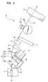
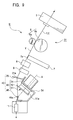
- the yarn slack eliminating device 10 uses the upstream guide 25 to guide the yarn Y spun by the spinning device 5 of the spinning unit U to the proximal end B of the outer peripheral surface 23a of the slack eliminating roller 23 and then wind the yarn Y around the proximal end B as shown in Figure 4. Further, the yarn slack eliminating device 10 unwinds the yarn from a leading end D of the slack eliminating roller 23 toward the downstream guide 26 as shown in Figures 5 and 6.
- the driving means 24 is composed of an electric motor and has an output shaft 24a to which the slack eliminating roller 23 is attached. Although not shown, the driving means 24 may be formed to transmit the rotative power of a line shaft driving the yarn feeding section 6, to the slack eliminating roller 23 via a transmission belt or the like to rotate the slack eliminating roller 23 at all times.
- the upstream guide 25 is used to guide the yarn Y to the proximal end B of the outer peripheral surface 23a of the slack eliminating roller 23.
- the upstream guide 25 stabilizes that position on the slack eliminating roller 23 to which the yarn Y is supplied. Accordingly, the yarn Y can be regularly wound around the slack eliminating roller 23.
- a yarn guide point 25a of the upstream guide 25 with which the yarn is contacted and guided is located above the slack eliminating roller 23.
- the yarn guide point 25a is arranged at a position corresponding to a right half R of the slack eliminating roller 23 if a rotating direction K of the slack eliminating roller 23 is rightward with respect to the front surface of the slack eliminating roller 23 as shown in Figure 4.
- the yarn guide point 25a is arranged at a position corresponding to a left half of the roller if the rotating direction K is leftward.
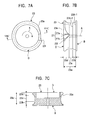
- the yarn guide 25a of the upstream guide 25 is positioned so that the yarn Y is introduced into a larger-diameter side of a tapered portion 23b (see Figure 7B) formed at the proximal end B of the slack eliminating roller 23 and having a diameter decreasing gradually toward the leading end D of the slack eliminating roller 23.
- the thus positioned yarn guide point 25a allows the yarn to be supplied to and wound around the larger-diameter side of the tapered portion 23b. Accordingly, the wound yarn moves toward a smaller-diameter side of the tapered portion 23b. This enables the yarn Y to be regularly wound around the slack eliminating roller 23.
- the downstream guide 26 is moved forward and backward between its forward position F at which the yarn Y being guided through the yarn guide point 26a is caught on the slack eliminating roller 23 as shown in Figures 3 and 4, and its backward position G at which the yarn guide point 26a is located on the centerline of rotation A in front of the leading end D of the slack eliminating roller 23 as shown in Figures 5 and 6.
- the downstream guide 26 is moved forward and backward by being pivotally supported around a pivoting portion 28 so as to be rotatively movable or being slidably guided along the centerline of rotation A using a slider or the like (not shown in the drawings).
- the yarn slack eliminating device 10 can stably move the yarn Y traveling through the yarn guide point 26a of the downstream guide 26, between a position at which the yarn Y is caught and a position at which the yarn Y is unwound while guiding the yarn Y by the downstream guide 26.
- the outer peripheral surface 23a of the slack eliminating roller 23 is shaped to have the tapered portion 23b at the proximal end B, which has the diameter decreasing gradually toward the leading end D of the slack eliminating roller 23, a flange portion 23d at the leading end D of the slack eliminating roller 23, and a cylindrical portion 23c of a uniform diameter between the tapered portion 23b and the flange portion 23d.
- the yarn Y can be regularly wound around the cylindrical portion 23c because the yarn Y supplied to and wound around the larger-diameter part 23b-2 of the tapered portion 23b moves to the smaller-diameter part 23b-1 of the tapered portion 23b and then reaches the cylindrical portion 23c of the uniform diameter (see Figure 4). Further, the yarn Y can be drawn out sequentially starting with its part wound first because during unwinding, the flange portion 23d at the leading end D of the slack eliminating roller 23 hinders the whole yarn Y wound around the cylindrical portion 23c from slipping off the cylindrical portion 23c at a time (see Figures 5 and 6).
- the slack eliminating roller 23 is provided with a notch portion 27 in a part of circumference of the flange portion 23d at its leading end D.
- the yarn moved to the flange portion 23d is caught in the notch portion 27 (see Figure 3) to allow the start of supply of the yarn Y to the proximal end B of the slack eliminating roller 23.
- the notch portion 27 is a substantially V shaped recess tapered from the leading end D to proximal end B of the slack eliminating roller 23.
- the notch portion 27 is formed of a catching portion 27a parallel with the centerline of rotation A and an escape portion 27b inclined in the rotating direction K so as to allow the yarn Y to be easily introduced into the notch portion 27.
- the slack eliminating roller 23 can start supplying the yarn to the proximal end B of the slack eliminating roller 23 by moving the downstream guide 26 from its backward position G to forward position F to move the traveling yarn Y into the notch portion 27 so that the yarn Y can be caught in the catching portion 27a of the notch portion 27.
- the slack eliminating roller 23 is provided with chamfered portions 23e, 23f in an outer periphery of the flange portion 23d and adjacent to the notch portion 27. Accordingly, when the yarn Y is unwound while being moved in a direction opposite to the winding direction, the chamfered portions 23e, 23f guide the yarn Y to prevent it from being caught in the notch portion 27 (see Figure 7).
- the slack eliminating roller 23 can smoothly unwind the yarn Y by causing the chamfered portions 23e, 23f to guide the yarn Y to prevent it from being caught in the notch portion 27.
- the downstream guide 26 is moved from its backward position G (see Figure 5) to forward position F (see Figure 3) to catch the traveling yarn Y on the slack eliminating roller 23 at the same time when or immediately after a spinning-side yarn Y1 is stopped (clamped) at the yarn piecing device 17 (see Figure 1) for yarn piecing. If the yarn Y is caught too early, due to the movement of the downstream guide 26 and the winding of the yarn around the slack eliminating roller 23, the yarn being guided to the yarn piecing device 17 is pulled. This may result in a yarn piecing error.
- the use of the above timing enables the yarn Y1 located downstream of the slack eliminating roller 23 and guided to the yarn piecing device 17 to be pieced without being moved even if it is pulled to the slack eliminating roller 23, around which it is being wound (see Figure 4). Further, during yarn piecing, the yarn Y1 delivered by the spinning device 5 is wound around the slack eliminating roller 23 and thus prevented from being slacked.
- the yarn tension adjusting device 11, provided downstream of the yarn slack eliminating device 10, is selected to be of a well-known type in which, for example, the yarn is tensed by a movable guide roller urged away from a fixed guide roller, though not shown in detail.
- the winding device 12 comprises a friction roller 13 and a cradle arm 14.
- the winding device 12 is configured to form the package 16 by contacting a bobbin 15 rotatably gripped by the cradle arm 14 with the friction roller 11, while winding the yarn around the bobbin 15.
- the suction pipe 18, provided on the working carriage 3 for yarn piecing is arranged so as to be rotatively movable around a pivoting portion 20.
- the suction pipe 18 functions as a spinning-side sucking member as described below.
- a suction opening 18a located at the leading end of the suction pipe 18 is rotatively moved upward as shown by an alternate long and two short dashes line in the figure and thus moved to the vicinity of a yarn discharge port of the spinning device 5, to suck the spun yarn Y.
- the suction opening 18a is rotatively moved downward as shown by a solid line in the figure to guide the yarn Y to the yarn piecing device 17.
- the suction mouth 19 is provided so as to be rotatively movable around a pivoting portion 21.
- the suction mouth 19 functions as a winding-side suction member as described below.
- the a suction opening 19a located at the leading end of the suction mouth 19 is rotatively moved downward as shown by an alternate long and two short dashes line in the figure and suck a yarn end of the package 16 separated from the friction roller 13 and stopped rotating, to withdraw the yarn. Then, while the yarn is being sucked, the suction opening 19a is rotatively moved upward as shown by a solid line in the figure to guide a package-side yarn Y2 to the yarn piecing device 17.
- the yarn piecing device 17, the suction pipe 18 and the suction mouth 19 are provided on the working carriage 3, which runs along the direction in which the spinning units U are juxtaposed. This eliminates the need to provid these components in each spinning unit U. As a result, the structure is simplified.
- a bundle of fibers S is drafted by the draft section 4 and then placed in the spinning device 5. Then, the bundle of fibers S is twisted by a whirling air current occurring in the spinning device 5, to generate a yarn Y. Subsequently, the yarn Y is fed downstream while being sandwiched between the nip roller 6a and the delivery roller 6b, which constitute the yarn feeding section 6. Then, as shown in Figure 2, the yarn Y is passed by the suction opening 7a of the yarn sucking device 7 and then the yarn defect detector 9. The yarn Y is then fed to the winding device 12 without contacting with the slack eliminating roller 23 of the yarn slack eliminating device 10. The yarn Y is then wound into the package 16 rotating in contact with the friction roller 13.
- the cutter 8 is activated to cut the yarn Y.
- the package-side cut yarn Y which is engaged with the package 16 is wound around the package 16. Further, the draft section 4 stops rotating the back roller 4a and the third roller 4b to cut the bundle of fibers S between the third roller 4b and the second roller 4d, which is still rotating.
- the spining device-side yarn Y engaged with the spinning device 5 and the bundle of fibers S which are separated by this cutting and the cutting with the cutter 8 are sucked and removed by the yarn sucking device 7, while being fed by the second roller 4d and the front roller 4e which are still rotating.
- the back roller 4a and third roller 4b of the draft section 4, which have been stopped, are activated to cause the second roller 4d and the front roller 4e which are still rotating to draft the bundle of fibers S. Further, the bundle of fibers S is fed into the spinning device 5. A spinning operation is then resumed to generate the yarn Y. As shown by an alternate long and two short dashes line in the figure, a yarn end of the yarn Y1 generated and continuously spun out is sucked and caught in the suction pipe 18, which has moved its suction opening 18a to the vicinity of a yarn discharge opening in the spinning device 5.
- the suction pipe 18 is rotatively moved downward to introduce the yarn Y1 into the yarn feeding section 6 from a side of the nip roller 6a.
- the yarn Y1 is then guided to the yarn piecing device 17.
- the suction opening 7a in the yarn sucking device 7 is closed.
- the suction mouth 19 rotatively moves the suction opening 19a, located at its leading end, downward as shown by an alternate long and two short dashes line in the figure.
- the suction opening 19a is rotatively moved upward as shown by a solid line in the figure.
- a package-side yarn Y2 engaged with the package 16 is positioned close to the yarn piecing device 17.
- a yarn handing lever of a yarn handling member (not shown in the drawings) is rotatively moved to introduce the spinning device-side yarn end Y1 engaged with the spinning device 5 and the package-side yarn end Y2 engaged with the package 16, into a yarn piecing section of the yarn piecing device 17 for yarn piecing, the yarn ends Y1, Y2 being positioned close to the yarn piecing device 17.
- the yarn slack eliminating device 10 moves the downstream guide 26 from its backward position G to forward position F simultaneously with or a very short time (for example, 5 msec.) after an operation of stopping the yarn after the yarn handling (yarn clamping operation).
- the traveling yarn Y1 is caught on and wound around the slack eliminating roller 23 to store, on the slack eliminating roller 23, a slack in the yarn Y1 that may occur between the spinning device 5 and the yarn piecing device 17 during a yarn piecing operation (rotation of a knotter head or the like). If this movement of the downstream guide 26 occurs before the yarn stopping operation is started, during a yarn piecing operation, due to the movement of the downstream guide 26 and the winding of the yarn around the slack eliminating roller 23, the yarn Y is pulled toward the slack eliminating roller 23. This may result in a yarn piecing error. On the other hand, if this movement occurs a long time after the yarn stopping operation is started, the yarn Y sequentially spun out by the spinning device 5 is slacked and fails to be caught in the slack eliminating roller 23.
- the spinning machine 1 moves the downstream guide 26 of the yarn slack eliminating device 10 from its forward position F (see Figure 4) to backward position G (see Figure 6). Further, the package 16 is contacted with the friction roller 13 to resume winding. The pieced yarn Y is wound around the package 16, which has restarted to be rotated, as well as the yarn Y unwound from the slack eliminating roller 23 (see Figure 6). The yarn Y1 unwound from the slack eliminating roller 23 is subjected to a moderate tension by the yarn tension adjusting device 11 and is then smoothly wound around the package 16.
- the yarn Y can be naturally separated from the slack eliminating roller 23 by setting the speed at which the yarn is unwound from the slack eliminating roller 23 (i.e. the speed at which the yarn is wound around the package 16) to be higher than the speed at which the yarn Y spun out by the spinning device 5 is wound around the slack eliminating roller 23, to unwind the whole yarn stored on the slack eliminating roller 23.
- the speed at which the yarn is unwound from the slack eliminating roller 23 i.e. the speed at which the yarn is wound around the package 16
- Figure 8 is a side view showing essential parts of a second embodiment of a spinning machine comprising a yarn slack eliminating device according to the present invention.
- An alternate long and short dash line L1 shows that the slack eliminating roller 23 is eliminating slack from the yarn.
- a solid line L2 shows that the yarn is being unwound from the slack eliminating roller 23.
- An alternate long and two short dashes line L3 shows that the yarn is traveling without having its slack eliminated by the slack eliminating roller 23.
- the present embodiment is markedly different from the first embodiment in that the slack eliminating roller 23 is arranged so that its centerline of rotation A extends in a horizontal direction and that the yarn sucking device 7, the cutter 8 and the yarn defect detector 9 are arranged downstream of the slack eliminating roller 23. Except for these points, the configuration of the present embodiment is substantially the same as that of the first embodiment.
- Figures 9 and 12 show a third embodiment of a yarn slack eliminating device according to the present invention.
- Figure 9 is an enlarged side view showing the vicinity of a yarn slack eliminating device of a spinning machine. This figure shows a state observed immediately before the yarn is caught on a roller main body 51 of a slack eliminating roller 43.
- Figure 10 is a plan view showing the slack eliminating roller 43 with an electric motor. This figure shows that a catching member 52 has been moved backward.
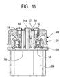
- Figure 11 is a front sectional view taken along line XI-XI in Figure 10.
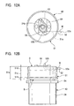
- Figure 12 shows the slack eliminating roller 43 with the electric motor. This figure shows that the catching member 52 has been projected.
- Figure 12A is a plan view
- Figure 12B is a front view.
- a spinning machine 31 according to the present embodiment differs from the spinning machine 1 according to the first embodiment (see Figures 1 to 7) in the slack eliminating roller 43 and a downstream guide 46 of a yarn slack eliminating device 40 provided in each spinning unit U. Except for these points, the configuration of the present embodiment is substantially the same as that of the first embodiment.
- the same reference numerals as those shown in Figures 1 to 7 denote the same components and the like.
- the roller main body 51 rotatively driven by the driving means 24, is provided with the catching member 52 so that the catching member 52 can be freely moved forward and backward.
- the roller main body 51 of the slack eliminating roller 43 is stopped or is rotating at a fixed speed, the catching member 52 has its leading end 52a pulled into the roller main body 51 owing to the resilience of urging means such as a spring and cannot catch the yarn (see Figure 10).
- the leading end 52a projects from the roller main body 51 to its catching position M against the resilience of the urging means 53 (see Figure 12).
- the slack eliminating roller 43 comprises the roller main body 51 rotatably supported, via a bearing member 55 such as a ball bearing, on a fixing portion 54 such as a bracket on which the driving means 24 is mounted, the bar-like catching member 52 slidably inserted through an insertion hole 51a in the roller main body 51, a boss portion 56 secured to the output shaft 24a of the driving means 24, a pivoting member 58 which pivotally supports the boss portion 56 around a pivoting portion 57 and on which a bent rear end 52b of the catching member 52 is locked, a regulating member 59 attached to the roller main body 51 using screws or the like, in order to regulate the pivoting of the pivoting member 58, and the urging means 53 arranged between the regulating member 59 and the pivoting member 58 and composed of a helical spring or the like.
- the urging means 53 always acts in a direction in which the catching member 52 is moved back into the roller main body 51.
- the catching member 52 is adapted to
- the catching member 52 projects from the roller main body 51 to its catching position M (see Figure 12) on the basis of the relationship between centrifugal force generated in the catching member 52 (the force acting in the direction in which the catching member 52 is projected) and inertia force generated in the roller main body 51 (the force acting in the direction in which the catching member 52 is projected), and the elastic force of the urging means 53 (the force acting in the direction in which the catching member 52 is moved back).
- the catching member 52 starts moving backward to its backward position N (see Figure 10) in the roller main body 51.
- a yarn guide point 46a of the downstream guide 46 which guides the yarn Y is located at a predetermined position on the centerline of rotation of the slack eliminating roller 43.
- the yarn Y extended between the yarn guide point 46a and the yarn guide point 25a of the upstream guide 25 is fed downstream without contacting with the slack eliminating roller 43 when the catching member 52 of the slack eliminating roller 43 has moved backward to the backward position N (see Figure 10) and pulled into the roller main body 51.
- the catching member 52 of the slack eliminating roller 43 projects to its catching position M (see Figure 12)
- the yarn is caught on the leading end 52a of the catching member 52 and wound around the outer peripheral surface 51a of the roller main body 51 for storage.
- the slack eliminating device 40 when the slack eliminating roller 43 is activated at the same time when or immediately after the yarn Y directed to the yarn piecing device 17 (see Figure 1) is stopped (clamped) for yarn piecing, the catching member 52 projects to its catching position M. Accordingly, the yarn Y delivered by the spinning device 5 can be wound around the roller main body 51 of the slack eliminating roller 43 to eliminate slack.
- the yarn Y can be caught on and unwound from the slack eliminating roller 43 with the yarn guide point 46a of the downstream guide 46 stopped at a predetermined position.
- the winding device 12 pulls the yarn wound around and stored on the outer peripheral surface of the roller main body 51 to unwind it from the leading end D of the slack eliminating roller 43 to the downstream guide 46.
- the outer peripheral surface 51a of the roller main body 51 of the slack eliminating roller 43 is shaped to have the tapered portion 51b at the proximal end B, which has the diameter decreasing gradually toward the leading end D of the slack eliminating roller 43, a flange portion 51d at the leading end D of the slack eliminating roller 43, and an intermediate tapered portion 51c between the tapered portion 51b and the flange portion 51d.
- the intermediate tapered portion 51c has a diameter decreasing gradually toward the leading end D of the slack eliminating roller 43.
- the magnitude of a gradual decrease in the diameter of the intermediate portion 51c is smaller than that of a gradual decrease in the diameter of the tapered portion 51b at the proximal end B.
- the yarn Y supplied to the tapered portion 51b at the proximal end B by the upstream guide 25 is guided to the intermediate tapered portion 51c. Accordingly, the yarn Y can be regularly wound around the intermediate tapered portion 51c. Further, the wound yarn can be gradually moved toward the leading end D of the slack eliminating roller 43, i.e. in the direction in which the diameter of the slack eliminating roller 43 decreases gradually. Moreover, during unwinding, the flange portion 51d at the leading end D of the slack eliminating roller 43 hinders the whole yarn wound around the intermediate tapered portion 51c from slipping off this portion 51c at a time. Consequently, the yarn Y can be sequentially drawn out starting with its part wound first.
- the position on the slack eliminating roller to which the yarn is supplied is stabilized Accordingly, the yarn can be regularly wound around the slack eliminating roller, and the wound yarn can be regularly unwound. This avoids troubles such as yarn breakage.
- the direction in which the yarn approaches the slack eliminating roller is the same as the direction in which the slack eliminating roller is rotated. Consequently, the position on the slack eliminating roller to which the yarn is supplied is stabilized, thus enabling the yarn to be regularly wound around the slack eliminating roller.
- the yarn supplied to and wound around the larger-diameter side of the tapered portion of the slack eliminating roller moves toward the smaller-diameter side of the tapered portion. Therefore, the yarn can be regularly wound around the slack eliminating roller.
- the yarn can be regularly wound around the slack eliminating roller. Further, the wound yarn can be regularly unwound from the slack eliminating roller.
- the traveling yarn is moved to the notch portion, which then catches the yarn. Then, it is possible to start supplying the yarn to the proximal end of the slack eliminating roller. This simplifies the structure of the catching means.
- the catching means does not obstruct unwinding. Therefore, the yarn can be smoothly unwound from the slack eliminating roller.
- the yarn delivered by the spinning device during yarn piecing is wound around the slack eliminating roller to prevent slack. Further, the yarn can be pieced while the yarn guided to the yarn piecing device is stopped. This ensures yarn piecing.
- the yarn can be moved between the position at which it is caught and the position at which it is unwound without being caught, while being guided by the downstream guide. This enables the yarn to be reliably caught and unwound.
- the yarn slack eliminating device for the spinning machine With the yarn slack eliminating device for the spinning machine according to the aspect of the present invention set forth in Claim 9, the yarn can be caught on and unwound from the slack eliminating roller by pushing out and pulling back the catching member. This simplifies the whole structure.
- the yarn unwound from the slack eliminating roller and traveling to the winding section is subjected to a moderate tension. This ensures that the yarn travels smoothly both during and after unwinding.
- the cut yarn does not remain on the slack eliminating roller.
Landscapes
- Engineering & Computer Science (AREA)
- Textile Engineering (AREA)
- Mechanical Engineering (AREA)
- Spinning Or Twisting Of Yarns (AREA)
- Forwarding And Storing Of Filamentary Material (AREA)
- Replacing, Conveying, And Pick-Finding For Filamentary Materials (AREA)
Applications Claiming Priority (2)
| Application Number | Priority Date | Filing Date | Title |
|---|---|---|---|
| JP2002293465 | 2002-10-07 | ||
| JP2002293465A JP4048902B2 (ja) | 2002-10-07 | 2002-10-07 | 紡績機の糸弛み取り装置 |
Publications (2)
| Publication Number | Publication Date |
|---|---|
| EP1407995A2 true EP1407995A2 (fr) | 2004-04-14 |
| EP1407995A3 EP1407995A3 (fr) | 2004-11-17 |
Family
ID=32025480
Family Applications (1)
| Application Number | Title | Priority Date | Filing Date |
|---|---|---|---|
| EP03021099A Withdrawn EP1407995A3 (fr) | 2002-10-07 | 2003-09-18 | Dispositif d'élimination des relâchements de fil pour des machines à filer |
Country Status (3)
| Country | Link |
|---|---|
| EP (1) | EP1407995A3 (fr) |
| JP (1) | JP4048902B2 (fr) |
| CN (2) | CN101033566B (fr) |
Cited By (9)
| Publication number | Priority date | Publication date | Assignee | Title |
|---|---|---|---|---|
| EP2216432A1 (fr) * | 2009-02-04 | 2010-08-11 | Murata Machinery, Ltd. | Procédé de traitement de fils et fileuse |
| EP2298971A1 (fr) * | 2009-08-10 | 2011-03-23 | Murata Machinery, Ltd. | Machine à filer avec rouleau accumulateur de fil |
| CN101994176A (zh) * | 2009-08-17 | 2011-03-30 | 村田机械株式会社 | 纺纱机械 |
| EP2075359A3 (fr) * | 2007-12-27 | 2011-05-11 | Murata Machinery, Ltd. | Dispositif d'élimination du relâchement des fils et machine de filature |
| EP2392531A3 (fr) * | 2010-06-02 | 2012-10-10 | Murata Machinery, Ltd. | Dispositif d'accumulation de fils |
| EP2573224A3 (fr) * | 2011-09-20 | 2015-06-17 | Murata Machinery, Ltd. | Unité de filage et dispositif de filage |
| EP2910507A1 (fr) * | 2014-02-25 | 2015-08-26 | Murata Machinery, Ltd. | Dispositif d'accumulation de fil, unité de bobinage de fil le comprenant et machine de bobinage de fil comprenant cette unité |
| EP2366817B2 (fr) † | 2008-11-28 | 2018-01-10 | Murata Machinery, Ltd. | Machine de filature |
| CN110699796A (zh) * | 2019-11-07 | 2020-01-17 | 浙江日发纺织机械股份有限公司 | 一种纱线的纺纱机构 |
Families Citing this family (15)
| Publication number | Priority date | Publication date | Assignee | Title |
|---|---|---|---|---|
| JP2008105755A (ja) * | 2006-10-23 | 2008-05-08 | Murata Mach Ltd | 電磁式テンサーを組み込んだ糸弛み取り装置 |
| JP5007826B2 (ja) * | 2008-03-31 | 2012-08-22 | 村田機械株式会社 | 糸巻取装置及びこの糸巻取装置を備える自動ワインダ |
| JP2010077576A (ja) | 2008-09-29 | 2010-04-08 | Murata Machinery Ltd | 紡績機 |
| JP2010089908A (ja) * | 2008-10-08 | 2010-04-22 | Murata Machinery Ltd | 糸弛み取り装置及びこれを備える繊維機械 |
| JP2010242907A (ja) * | 2009-04-08 | 2010-10-28 | Mitsutoyo Corp | 移動機構の防塵装置および測定機 |
| JP2011038189A (ja) * | 2009-08-06 | 2011-02-24 | Murata Machinery Ltd | 紡績機及び糸貯留ローラに残留した紡績糸の除去方法 |
| EP2484620B1 (fr) * | 2009-09-30 | 2015-11-04 | Murata Machinery, Ltd. | Bobinoir de fil |
| JP2011184181A (ja) * | 2010-03-11 | 2011-09-22 | Murata Machinery Ltd | 糸巻取機 |
| CN102154741A (zh) * | 2010-12-14 | 2011-08-17 | 江苏华佳丝绸有限公司 | 一种强捻纱防捻缩装置 |
| CN102560835B (zh) * | 2012-03-12 | 2014-04-16 | 天津海天长丰科技开发有限公司 | 织机自动放纬、喂纬装置 |
| JP2014009052A (ja) * | 2012-06-28 | 2014-01-20 | Murata Mach Ltd | 繊維機械 |
| JP2014009409A (ja) * | 2012-06-28 | 2014-01-20 | Murata Mach Ltd | 糸貯留装置、紡績ユニット、および紡績機 |
| JP2014088638A (ja) * | 2012-10-30 | 2014-05-15 | Murata Mach Ltd | 糸巻取機及び糸巻取方法 |
| JP2016204062A (ja) * | 2015-04-16 | 2016-12-08 | 村田機械株式会社 | 繊維機械 |
| FR3118896B1 (fr) * | 2021-01-19 | 2023-07-14 | Safran Aircraft Engines | Procede de fabrication d’une preforme pour une piece de turbomachine et installation de tissage d’une telle preforme |
Family Cites Families (6)
| Publication number | Priority date | Publication date | Assignee | Title |
|---|---|---|---|---|
| IT1065039B (it) * | 1975-12-23 | 1985-02-25 | Schubert & Salzer Maschinen | Dispositivo di filatura ad estremita'aperta |
| US4185761A (en) * | 1977-11-25 | 1980-01-29 | Kabushiki Kaisha Toyada Jidoshokki Seisakusho | Pressure roller in spinning machine |
| DE3238376C2 (de) * | 1982-10-16 | 1984-08-09 | Schubert & Salzer Maschinenfabrik Ag, 8070 Ingolstadt | Fadenspeicher |
| US4553709A (en) * | 1982-10-16 | 1985-11-19 | Schubert & Salzer | Yarn accumulator |
| DE4104863A1 (de) * | 1991-02-16 | 1992-08-20 | Fritz Stahlecker | Vorrichtung zum zwischenspeichern eines fadens |
| DE19503729C1 (de) * | 1995-02-04 | 1996-08-14 | Fraunhofer Ges Forschung | Verfahren und Vorrichtung zum Zwischenspeichern von biegeschlaffe Wickelgut |
-
2002
- 2002-10-07 JP JP2002293465A patent/JP4048902B2/ja not_active Expired - Fee Related
-
2003
- 2003-09-18 EP EP03021099A patent/EP1407995A3/fr not_active Withdrawn
- 2003-09-30 CN CN 200710096054 patent/CN101033566B/zh not_active Expired - Fee Related
- 2003-09-30 CN CNB031326900A patent/CN1333122C/zh not_active Expired - Fee Related
Cited By (10)
| Publication number | Priority date | Publication date | Assignee | Title |
|---|---|---|---|---|
| EP2075359A3 (fr) * | 2007-12-27 | 2011-05-11 | Murata Machinery, Ltd. | Dispositif d'élimination du relâchement des fils et machine de filature |
| EP2366817B2 (fr) † | 2008-11-28 | 2018-01-10 | Murata Machinery, Ltd. | Machine de filature |
| EP2216432A1 (fr) * | 2009-02-04 | 2010-08-11 | Murata Machinery, Ltd. | Procédé de traitement de fils et fileuse |
| EP2298971A1 (fr) * | 2009-08-10 | 2011-03-23 | Murata Machinery, Ltd. | Machine à filer avec rouleau accumulateur de fil |
| CN101994176A (zh) * | 2009-08-17 | 2011-03-30 | 村田机械株式会社 | 纺纱机械 |
| CN101994176B (zh) * | 2009-08-17 | 2014-07-09 | 村田机械株式会社 | 纺纱机械 |
| EP2392531A3 (fr) * | 2010-06-02 | 2012-10-10 | Murata Machinery, Ltd. | Dispositif d'accumulation de fils |
| EP2573224A3 (fr) * | 2011-09-20 | 2015-06-17 | Murata Machinery, Ltd. | Unité de filage et dispositif de filage |
| EP2910507A1 (fr) * | 2014-02-25 | 2015-08-26 | Murata Machinery, Ltd. | Dispositif d'accumulation de fil, unité de bobinage de fil le comprenant et machine de bobinage de fil comprenant cette unité |
| CN110699796A (zh) * | 2019-11-07 | 2020-01-17 | 浙江日发纺织机械股份有限公司 | 一种纱线的纺纱机构 |
Also Published As
| Publication number | Publication date |
|---|---|
| EP1407995A3 (fr) | 2004-11-17 |
| CN1497075A (zh) | 2004-05-19 |
| CN101033566B (zh) | 2010-05-26 |
| CN1333122C (zh) | 2007-08-22 |
| CN101033566A (zh) | 2007-09-12 |
| JP4048902B2 (ja) | 2008-02-20 |
| JP2004124333A (ja) | 2004-04-22 |
Similar Documents
| Publication | Publication Date | Title |
|---|---|---|
| EP1407995A2 (fr) | Dispositif d'élimination des relâchements de fil pour des machines à filer | |
| EP2468932B1 (fr) | Dispositif pour attraper l'extrémité des fils et son procédé de fonctionnement | |
| CN101522550B (zh) | 纺织机的工位 | |
| EP2284300B1 (fr) | Fileuse et procédé de retrait de fil pour retirer le fil restant sur le rouleau d'accumulation de fils | |
| EP2213773B2 (fr) | Dispositif de capture d'extrémité de fil et fileuse l'incluant | |
| EP1460015A1 (fr) | Bobinoir pour fil | |
| EP1457448A2 (fr) | Machines à filer avec un dispositif d'élimination des relâchements de fil | |
| EP2298971B1 (fr) | Machine à filer avec rouleau accumulateur de fil | |
| CN105645178A (zh) | 纱线卷取机 | |
| EP1457446B9 (fr) | Dispositif de réglage de tension et d'élimination des relâchements de fil pour un dispositif de bobinage | |
| CN108286093B (zh) | 一种纺纱机 | |
| EP1561717A1 (fr) | Procédé pour bobiner d'une réserve de fil sur une bobine vide et métier à filer avec un dispositif pour mettre en ouvre ledit procédé | |
| JP4082250B2 (ja) | 紡績機の糸弛み取り装置 | |
| JP2018159145A (ja) | 精紡機 | |
| JP4019984B2 (ja) | 紡績機 | |
| JP3952976B2 (ja) | 糸継ぎ装置を備えた紡績機 | |
| JP3888320B2 (ja) | 紡績機 | |
| JP2013057152A (ja) | 糸巻取機 | |
| JP2024007744A (ja) | 紡績機、パッケージの形成方法及びパッケージ | |
| EP2573229A2 (fr) | Dispositif de tirage et métier à filer | |
| JP2018159144A (ja) | 巻取機 | |
| CN115465731A (zh) | 纱线卷取机 | |
| JPH02234930A (ja) | 糸継ぎ方法、および装置 | |
| CN114575005A (zh) | 纺纱机和纺纱方法 | |
| JP2022085989A (ja) | 紡績機 |
Legal Events
| Date | Code | Title | Description |
|---|---|---|---|
| PUAI | Public reference made under article 153(3) epc to a published international application that has entered the european phase |
Free format text: ORIGINAL CODE: 0009012 |
|
| AK | Designated contracting states |
Kind code of ref document: A2 Designated state(s): AT BE BG CH CY CZ DE DK EE ES FI FR GB GR HU IE IT LI LU MC NL PT RO SE SI SK TR |
|
| AX | Request for extension of the european patent |
Extension state: AL LT LV MK |
|
| PUAL | Search report despatched |
Free format text: ORIGINAL CODE: 0009013 |
|
| AK | Designated contracting states |
Kind code of ref document: A3 Designated state(s): AT BE BG CH CY CZ DE DK EE ES FI FR GB GR HU IE IT LI LU MC NL PT RO SE SI SK TR |
|
| AX | Request for extension of the european patent |
Extension state: AL LT LV MK |
|
| 17P | Request for examination filed |
Effective date: 20050509 |
|
| AKX | Designation fees paid |
Designated state(s): CH DE LI |
|
| 17Q | First examination report despatched |
Effective date: 20061109 |
|
| STAA | Information on the status of an ep patent application or granted ep patent |
Free format text: STATUS: THE APPLICATION HAS BEEN WITHDRAWN |
|
| 18W | Application withdrawn |
Effective date: 20130414 |