EP1409444B1 - Verbesserte verfahren zur kontinuierlichen herstellung von essigsäure und/oder essigsäuremethylester - Google Patents
Verbesserte verfahren zur kontinuierlichen herstellung von essigsäure und/oder essigsäuremethylester Download PDFInfo
- Publication number
- EP1409444B1 EP1409444B1 EP02762492A EP02762492A EP1409444B1 EP 1409444 B1 EP1409444 B1 EP 1409444B1 EP 02762492 A EP02762492 A EP 02762492A EP 02762492 A EP02762492 A EP 02762492A EP 1409444 B1 EP1409444 B1 EP 1409444B1
- Authority
- EP
- European Patent Office
- Prior art keywords
- reactor
- zone
- process according
- carbon monoxide
- methanol
- Prior art date
- Legal status (The legal status is an assumption and is not a legal conclusion. Google has not performed a legal analysis and makes no representation as to the accuracy of the status listed.)
- Expired - Lifetime
Links
- QTBSBXVTEAMEQO-UHFFFAOYSA-N Acetic acid Chemical compound CC(O)=O QTBSBXVTEAMEQO-UHFFFAOYSA-N 0.000 title claims abstract description 220
- 238000000034 method Methods 0.000 title claims abstract description 68
- XBDQKXXYIPTUBI-UHFFFAOYSA-M Propionate Chemical compound CCC([O-])=O XBDQKXXYIPTUBI-UHFFFAOYSA-M 0.000 title claims abstract description 52
- KXKVLQRXCPHEJC-UHFFFAOYSA-N acetic acid trimethyl ester Natural products COC(C)=O KXKVLQRXCPHEJC-UHFFFAOYSA-N 0.000 title claims abstract description 52
- 230000006872 improvement Effects 0.000 title description 7
- 238000010924 continuous production Methods 0.000 title description 2
- OKKJLVBELUTLKV-UHFFFAOYSA-N Methanol Chemical compound OC OKKJLVBELUTLKV-UHFFFAOYSA-N 0.000 claims abstract description 173
- UGFAIRIUMAVXCW-UHFFFAOYSA-N Carbon monoxide Chemical compound [O+]#[C-] UGFAIRIUMAVXCW-UHFFFAOYSA-N 0.000 claims abstract description 76
- 229910002091 carbon monoxide Inorganic materials 0.000 claims abstract description 73
- XLYOFNOQVPJJNP-UHFFFAOYSA-N water Substances O XLYOFNOQVPJJNP-UHFFFAOYSA-N 0.000 claims abstract description 73
- 230000008569 process Effects 0.000 claims abstract description 56
- 238000004519 manufacturing process Methods 0.000 claims abstract description 50
- 238000006243 chemical reaction Methods 0.000 claims abstract description 48
- 239000007788 liquid Substances 0.000 claims abstract description 47
- 239000012429 reaction media Substances 0.000 claims abstract description 41
- 238000005810 carbonylation reaction Methods 0.000 claims abstract description 37
- 230000006315 carbonylation Effects 0.000 claims abstract description 33
- 238000004821 distillation Methods 0.000 claims abstract description 26
- 239000007791 liquid phase Substances 0.000 claims abstract description 21
- 238000009434 installation Methods 0.000 claims abstract description 20
- 238000000746 purification Methods 0.000 claims abstract description 16
- 239000000203 mixture Substances 0.000 claims abstract description 12
- 238000009834 vaporization Methods 0.000 claims abstract description 10
- 239000000470 constituent Substances 0.000 claims abstract description 9
- 230000008016 vaporization Effects 0.000 claims abstract description 8
- 239000002815 homogeneous catalyst Substances 0.000 claims abstract description 3
- 238000013022 venting Methods 0.000 claims abstract 4
- INQOMBQAUSQDDS-UHFFFAOYSA-N iodomethane Chemical group IC INQOMBQAUSQDDS-UHFFFAOYSA-N 0.000 claims description 16
- 239000003054 catalyst Substances 0.000 claims description 13
- 238000002360 preparation method Methods 0.000 claims description 9
- 230000036961 partial effect Effects 0.000 claims description 8
- 229910052703 rhodium Inorganic materials 0.000 claims description 8
- 239000010948 rhodium Substances 0.000 claims description 8
- MHOVAHRLVXNVSD-UHFFFAOYSA-N rhodium atom Chemical compound [Rh] MHOVAHRLVXNVSD-UHFFFAOYSA-N 0.000 claims description 8
- 238000011144 upstream manufacturing Methods 0.000 claims description 7
- 229910052741 iridium Inorganic materials 0.000 claims description 6
- GKOZUEZYRPOHIO-UHFFFAOYSA-N iridium atom Chemical compound [Ir] GKOZUEZYRPOHIO-UHFFFAOYSA-N 0.000 claims description 6
- 230000001105 regulatory effect Effects 0.000 claims description 6
- BASFCYQUMIYNBI-UHFFFAOYSA-N platinum Chemical compound [Pt] BASFCYQUMIYNBI-UHFFFAOYSA-N 0.000 claims description 4
- 229910052751 metal Inorganic materials 0.000 claims description 2
- 239000002184 metal Substances 0.000 claims description 2
- 229910052697 platinum Inorganic materials 0.000 claims description 2
- 239000003426 co-catalyst Substances 0.000 claims 2
- 238000007599 discharging Methods 0.000 claims 1
- 238000012544 monitoring process Methods 0.000 abstract description 5
- 230000009471 action Effects 0.000 description 28
- 229910052739 hydrogen Inorganic materials 0.000 description 17
- 239000001257 hydrogen Substances 0.000 description 17
- 239000007789 gas Substances 0.000 description 15
- CURLTUGMZLYLDI-UHFFFAOYSA-N Carbon dioxide Chemical compound O=C=O CURLTUGMZLYLDI-UHFFFAOYSA-N 0.000 description 13
- 235000021183 entrée Nutrition 0.000 description 13
- UFHFLCQGNIYNRP-UHFFFAOYSA-N Hydrogen Chemical compound [H][H] UFHFLCQGNIYNRP-UHFFFAOYSA-N 0.000 description 12
- 230000003197 catalytic effect Effects 0.000 description 12
- 238000004064 recycling Methods 0.000 description 10
- 229910002092 carbon dioxide Inorganic materials 0.000 description 9
- 238000012360 testing method Methods 0.000 description 9
- QTBSBXVTEAMEQO-UHFFFAOYSA-M Acetate Chemical compound CC([O-])=O QTBSBXVTEAMEQO-UHFFFAOYSA-M 0.000 description 8
- XBDQKXXYIPTUBI-UHFFFAOYSA-N Propionic acid Chemical compound CCC(O)=O XBDQKXXYIPTUBI-UHFFFAOYSA-N 0.000 description 8
- 125000002915 carbonyl group Chemical group [*:2]C([*:1])=O 0.000 description 8
- 239000012071 phase Substances 0.000 description 7
- 238000000926 separation method Methods 0.000 description 7
- 230000033228 biological regulation Effects 0.000 description 6
- 238000013178 mathematical model Methods 0.000 description 6
- 238000004458 analytical method Methods 0.000 description 5
- 238000004364 calculation method Methods 0.000 description 5
- 230000001276 controlling effect Effects 0.000 description 5
- 235000013305 food Nutrition 0.000 description 5
- 150000002431 hydrogen Chemical class 0.000 description 5
- 238000005259 measurement Methods 0.000 description 5
- LCGLNKUTAGEVQW-UHFFFAOYSA-N Dimethyl ether Chemical compound COC LCGLNKUTAGEVQW-UHFFFAOYSA-N 0.000 description 4
- 239000001569 carbon dioxide Substances 0.000 description 4
- 239000012295 chemical reaction liquid Substances 0.000 description 4
- 230000000694 effects Effects 0.000 description 4
- 230000004907 flux Effects 0.000 description 4
- VNWKTOKETHGBQD-UHFFFAOYSA-N methane Chemical compound C VNWKTOKETHGBQD-UHFFFAOYSA-N 0.000 description 4
- 238000010517 secondary reaction Methods 0.000 description 4
- WFDIJRYMOXRFFG-UHFFFAOYSA-N Acetic anhydride Chemical compound CC(=O)OC(C)=O WFDIJRYMOXRFFG-UHFFFAOYSA-N 0.000 description 3
- 241000196324 Embryophyta Species 0.000 description 3
- 239000002253 acid Substances 0.000 description 3
- 238000005755 formation reaction Methods 0.000 description 3
- 239000000463 material Substances 0.000 description 3
- 125000000896 monocarboxylic acid group Chemical group 0.000 description 3
- 235000019260 propionic acid Nutrition 0.000 description 3
- 238000010926 purge Methods 0.000 description 3
- IUVKMZGDUIUOCP-BTNSXGMBSA-N quinbolone Chemical compound O([C@H]1CC[C@H]2[C@H]3[C@@H]([C@]4(C=CC(=O)C=C4CC3)C)CC[C@@]21C)C1=CCCC1 IUVKMZGDUIUOCP-BTNSXGMBSA-N 0.000 description 3
- 238000011084 recovery Methods 0.000 description 3
- 230000004044 response Effects 0.000 description 3
- 238000007086 side reaction Methods 0.000 description 3
- 241000894007 species Species 0.000 description 3
- 238000001228 spectrum Methods 0.000 description 3
- 241001080024 Telles Species 0.000 description 2
- 238000009825 accumulation Methods 0.000 description 2
- 239000006227 byproduct Substances 0.000 description 2
- 238000006555 catalytic reaction Methods 0.000 description 2
- 230000000052 comparative effect Effects 0.000 description 2
- 239000012809 cooling fluid Substances 0.000 description 2
- 230000008878 coupling Effects 0.000 description 2
- 238000010168 coupling process Methods 0.000 description 2
- 238000005859 coupling reaction Methods 0.000 description 2
- 238000010586 diagram Methods 0.000 description 2
- 230000008030 elimination Effects 0.000 description 2
- 238000003379 elimination reaction Methods 0.000 description 2
- 238000004868 gas analysis Methods 0.000 description 2
- 238000012423 maintenance Methods 0.000 description 2
- 125000002496 methyl group Chemical group [H]C([H])([H])* 0.000 description 2
- 238000005457 optimization Methods 0.000 description 2
- 238000004886 process control Methods 0.000 description 2
- 239000000047 product Substances 0.000 description 2
- 230000002829 reductive effect Effects 0.000 description 2
- 230000000717 retained effect Effects 0.000 description 2
- 230000001052 transient effect Effects 0.000 description 2
- OKTJSMMVPCPJKN-UHFFFAOYSA-N Carbon Chemical compound [C] OKTJSMMVPCPJKN-UHFFFAOYSA-N 0.000 description 1
- KJTLSVCANCCWHF-UHFFFAOYSA-N Ruthenium Chemical compound [Ru] KJTLSVCANCCWHF-UHFFFAOYSA-N 0.000 description 1
- 240000008042 Zea mays Species 0.000 description 1
- 230000003044 adaptive effect Effects 0.000 description 1
- 230000003042 antagnostic effect Effects 0.000 description 1
- 238000013459 approach Methods 0.000 description 1
- 239000012223 aqueous fraction Substances 0.000 description 1
- 239000008346 aqueous phase Substances 0.000 description 1
- 230000008901 benefit Effects 0.000 description 1
- 230000015572 biosynthetic process Effects 0.000 description 1
- 238000009530 blood pressure measurement Methods 0.000 description 1
- 229910052799 carbon Inorganic materials 0.000 description 1
- 239000003153 chemical reaction reagent Substances 0.000 description 1
- 238000002485 combustion reaction Methods 0.000 description 1
- 230000000295 complement effect Effects 0.000 description 1
- 238000007796 conventional method Methods 0.000 description 1
- 238000001816 cooling Methods 0.000 description 1
- 238000010908 decantation Methods 0.000 description 1
- 230000003247 decreasing effect Effects 0.000 description 1
- 230000007812 deficiency Effects 0.000 description 1
- 230000001419 dependent effect Effects 0.000 description 1
- 239000006185 dispersion Substances 0.000 description 1
- 229940082150 encore Drugs 0.000 description 1
- 238000005886 esterification reaction Methods 0.000 description 1
- 238000004817 gas chromatography Methods 0.000 description 1
- 150000004820 halides Chemical class 0.000 description 1
- 238000011065 in-situ storage Methods 0.000 description 1
- 230000000670 limiting effect Effects 0.000 description 1
- 230000007257 malfunction Effects 0.000 description 1
- 238000001320 near-infrared absorption spectroscopy Methods 0.000 description 1
- 210000000056 organ Anatomy 0.000 description 1
- 239000012074 organic phase Substances 0.000 description 1
- 239000000376 reactant Substances 0.000 description 1
- 239000011541 reaction mixture Substances 0.000 description 1
- 238000007430 reference method Methods 0.000 description 1
- 238000010992 reflux Methods 0.000 description 1
- 229910052707 ruthenium Inorganic materials 0.000 description 1
- 238000005070 sampling Methods 0.000 description 1
- 238000012882 sequential analysis Methods 0.000 description 1
- 239000002904 solvent Substances 0.000 description 1
- 238000005507 spraying Methods 0.000 description 1
- 230000006641 stabilisation Effects 0.000 description 1
- 238000011105 stabilization Methods 0.000 description 1
- 238000003860 storage Methods 0.000 description 1
- 239000013589 supplement Substances 0.000 description 1
- 239000012808 vapor phase Substances 0.000 description 1
- 238000005406 washing Methods 0.000 description 1
Images
Classifications
-
- C—CHEMISTRY; METALLURGY
- C07—ORGANIC CHEMISTRY
- C07C—ACYCLIC OR CARBOCYCLIC COMPOUNDS
- C07C67/00—Preparation of carboxylic acid esters
- C07C67/36—Preparation of carboxylic acid esters by reaction with carbon monoxide or formates
-
- C—CHEMISTRY; METALLURGY
- C07—ORGANIC CHEMISTRY
- C07C—ACYCLIC OR CARBOCYCLIC COMPOUNDS
- C07C51/00—Preparation of carboxylic acids or their salts, halides or anhydrides
- C07C51/10—Preparation of carboxylic acids or their salts, halides or anhydrides by reaction with carbon monoxide
- C07C51/12—Preparation of carboxylic acids or their salts, halides or anhydrides by reaction with carbon monoxide on an oxygen-containing group in organic compounds, e.g. alcohols
-
- C—CHEMISTRY; METALLURGY
- C07—ORGANIC CHEMISTRY
- C07C—ACYCLIC OR CARBOCYCLIC COMPOUNDS
- C07C67/00—Preparation of carboxylic acid esters
- C07C67/36—Preparation of carboxylic acid esters by reaction with carbon monoxide or formates
- C07C67/37—Preparation of carboxylic acid esters by reaction with carbon monoxide or formates by reaction of ethers with carbon monoxide
Definitions
- the invention relates to an improvement in manufacturing processes for acetic acid and / or methyl acetate continuously.
- this improvement aims at improving the control and the conduct of a process for the preparation of acetic acid and / or methyl acetate, with a view to improving the production of acetic acid and / or acetate of methyl.
- the rhodium carbonylation process is a known process, exploited industrially and having been the subject of numerous articles and patents such as, for example, US Patents 3,769,329 and US 3,813,428.
- European patents EP 618 183 and EP 618 184 as well as European patents EP 785 919 and EP 759 022 describe a process for the carbonylation of methanol, in the presence of an iridium-based catalyst system, and where appropriate, containing in particular more rhodium.
- the improvement of these methods of carbonylation of methanol has aimed to increase the productivity of the catalysts and to reduce the manufacturing costs of acetic acid.
- the reaction zone consists of a stirred continuous reactor operating under pressure (5-200 bars) and at high temperature (150-250 ° C.).
- the liquid reaction medium produced is then sent to the second zone called vaporization zone or flash zone where the liquid is partially vaporized at a pressure lower than that of reaction.
- the flash zone allows the separation of the gas from the liquid, the vaporized flow then passes into the third so-called separation zone, while the liquid flow (essentially acetic acid containing the catalyst) is recycled to the first zone.
- the purification zone may comprise one to several distillation columns; it allows the separation of acetic acid and / or methyl acetate from the other constituents and the recycling of the streams to the reaction zone.
- a purge of the gases from the reactor head makes it possible to control the partial pressure level of carbon monoxide and to remove the gaseous by-products of the reaction, as well as the inerts present in the food carbon monoxide.
- the objective is to stabilize the temperature of the reactor, to increase the production of the unit: the establishment of a new control has thus reduced the standard deviation for the temperature from 3.6 to 0.8 ° C.
- the European patent application EP 0 983 752 has the object of setting up a control system which aims at keeping the carbon monoxide flow rate below a maximum calculated flow rate which represents an acceptable maximum flow rate.
- the European patent application EP 0 999 198 aims at maintaining the composition of the reaction medium, in particular the concentration of water and methyl acetate in the carbonylation reactor by recycling a stream of rich acetic acid from the purification zone of acid.
- Patents EP 0846674 and FR 2750984 describe the optimization of the CO consumption by introducing a second carbonylation reactor (finisher effect) between the 1st reactor (reaction zone) and the flash (area spraying).
- US Pat. No. 5,831,120 provides a technical solution for preventing the accumulation of water in the reaction medium and obtaining a target water concentration in the carbonylation reactor.
- the patent application EP 1 002 785 aims to maintain the concentration of methyl acetate in the reactor at a predetermined value by adjusting the ratio between methanol and methanol. carbon monoxide, a ratio that regulates the feed rate of methanol to the reactor.
- International patent application WO 00/37405 provides a method of controlling the process by measuring the concentrations of the various components of the reaction solution by means of an infra-red analyzer and adjusting in response the concentrations of at least catalytic species, methyl iodide, methyl acetate and water, to optimize the manufacture of acetic acid.
- the purpose of the present invention is precisely to overcome these drawbacks and provides a control method which acts automatically to maintain the concentrations, in particular of water and / or methyl acetate, and which makes it possible to maximize the production of acetic acid when the flow rate introduction of CO undergoes fluctuations, as will be described.
- This reaction causes a loss of carbon monoxide and a simultaneous production of hydrogen and carbon dioxide.
- the methyl acetate thus formed may interfere with the separation of the condensed liquid stream at the top of the first purification column if its concentration increases uncontrollably in the reactor.
- the flow of carbon monoxide can not be totally constant. Small variations can be damped by placing a buffer tank of carbon monoxide upstream of the acetic acid reactor, which can attenuate and smooth over time the carbon monoxide flow rate variations, as long as the The pressure level of the carbon monoxide source is greater than the level of the pressure of use in the carbonylation reactor.
- the improvement according to the invention consists in varying the reactor temperature and the feed rate of methanol in the reactor in order to adjust the production of acetic acid to the available carbon monoxide flow rate, while maintaining a selectivity hydrogen or CO 2 low, or conditions for optimizing the consumption of CO and this, in particular by using a previously programmed electronic device such as a predictive control multivariable controller.
- the reactor temperature varies to be able to use all available carbon monoxide.
- the present invention thus provides a means for better controlling the production of acetic acid and / or methyl acetate in a continuous process for the carbonylation of methanol or a carbonyl derivative of methanol with carbon monoxide, in the liquid phase in the presence of water and a homogeneous catalytic system implemented in an industrial installation comprising three main zones I, II and III defined above.
- carbonyl derivative of methanol is meant all the methanol derivatives conventionally used in industrial processes for the preparation of acetic acid and / or methyl acetate by carbonylation, for example dimethyl ether, methyl halides, or methyl acetate.
- control carried out in the context of the process according to the invention can be implemented by means of any electronic device making it possible to ensure the servocontrol sought, so as to to minimize losses of carbon monoxide when the carbon monoxide supply fluctuates.
- This servo device may, in particular, be an electronic control device previously programmed for this purpose.
- the servo-control device acts on the reactor temperature and on the methanol inlet flow rate in the reactor, so as to minimize the losses of carbon monoxide, and this, by controlling, continuously, the flow rate. input of carbon monoxide into the reactor and at least one of the parameters defining the composition of the reaction medium and / or vents.
- the parameter chosen, as the input of the device for realizing the servo-control depends on the operating mode of the process for manufacturing acetic acid and / or methyl acetate and that in particular, these parameters may be different, depending on whether it is a so-called conventional Monsanto type process, or a so-called "low water content” method, as appears in the description which follows.
- a multivariable predictive regulator was chosen to overcome the particularities related to the control-command systems on the one hand, and also to be able to directly use the programs provided with the multivariable controller.
- Such a device is based on the use of a mathematical model of regulation and allows a predictive control which, based on this mathematical model, makes a hypothesis on the future of the variable to be controlled.
- This second phase amounts to creating, in the regulator, a database representing the relations between the action variables and the objective variables.
- a calculation program supplied with the controller, then optimizes the control parameters, such as gain and delay, which will have to be applied to the electrical output signals of the regulator to control organs (typically valves) acting on the variables of the controller. 'action.
- the values of the action variables and objective variables that are supplied to the regulator are obtained during a preliminary experimental phase, without regulation, consisting of implementing the chemical reaction, to rapidly increment the value of one of the variables in order to evolve the system, and to observe the evolution of the different variables by continuously measuring their value.
- the regulator Once the regulator has been programmed, it is integrated in the driving position and is progressively looped on the process.
- the regulator regulates the objective variables around setpoint values, by acting on the action variables via the aforementioned members.
- the invention applies to the control of conventional carbonylation processes of methanol to acetic acid and / or methyl acetate using contents greater than or equal to 14% water.
- This mode of control works if the activity of the catalyst is sufficient.
- methanol not converted to acetic acid is esterified to methyl acetate.
- the rise in the concentration of methyl acetate in the reactor causes malfunctions in the purification zone, in particular at the top of the first purification column where the rise in the concentration of methyl acetate deteriorates first, and then inhibits the separation of the condensed liquid into two distinct liquid phases (a light aqueous phase which on the one hand serves the reflux of the column and on the other hand is recycled to the reactor, and a heavy organic phase which is completely recycled to the reactor of carbonylation).
- the level of production must then be reduced, to find a correct situation, to then add additional catalyst or increase the temperature of the reactor, to allow to work with a higher level of production.
- the selectivities are thus accessed by relating these partial flow rates to the total flow rate of carbon monoxide entering the reactor.
- the CO 2 selectivity is more representative of the gas-to-water reaction, but, sometimes for practical reasons, related to gas analysis, the hydrogen selectivity can be used to drive the industrial installation.
- good control of the reaction is obtained by varying the flow rate of methanol or carbonyl derivative of methanol used at the inlet of the reactor and the temperature of the reactor, to obtain a selectivity in hydrogen or CO 2 less than or equal to 0.01 and / or a concentration of methyl acetate in the reactor less than 5% by weight, preferably less than 2% by weight, which ensures a good settling at the head of the first purification column.
- the regulation relates to the CO 2 or H 2 selectivity and the rate of CO to be consumed and the regulator acts to both the reactor temperature and the flow rate of methanol (or carbonyl derivative) entering the reactor.
- the use of the regulator device in this first variant of the invention has made it possible to maintain the CO 2 (or hydrogen) selectivity in a small range of variation, by varying the reactor temperature and the inlet flow rate of the reactor. methanol (or carbonyl derivative) in the reactor, and allowed to optimize the consumption of carbon monoxide, even in the presence of relatively large fluctuations in the rate of entry of carbon monoxide into the reactor.
- the invention also applies to processes for manufacturing acetic acid and / or methyl acetate in the liquid phase in the presence of a homogeneous catalyst, referred to as a "low water content" process. that is, in the case where the water concentration in the reaction medium is less than 14% by weight.
- the objective variables of the regulator the water concentration which will be fixed at a predetermined value and the flow rate of carbon monoxide entering the reactor, will advantageously be retained as objective variables of the regulator.
- This predetermined value is advantageously set at a value between 50 and 100% of the absolute total scale of the levels in the reactor.
- the regulator used according to the invention can also be used to regulate the level of liquid in the reactor and, by adding as an action variable to the regulator the flow of liquid from the reactor to the flash and the different flow rates of the reactor. return to the reactor, in particular flows and liquid flows from zones II and III.
- the servocontrol device used according to the invention in particular the predictive multivariable regulator, can be used to control and regulate the water content in the reaction medium.
- It can in particular be used to control and regulate the equipment on the one hand to prevent the accumulation of water in the reaction medium, in particular in the case of a distillation column for subtracting water from the process of acetic acid preparation.
- This elimination or recovery can be carried out either at the outlet of the reactor via a heat exchanger placed on a recirculation loop of the reaction liquid towards said reactor or at the inlet of the reactor on recycle streams to said reactor. reactor.
- a set value of the flow rate of carbon monoxide is made dependent on the pressure inside said buffer tank.
- This discharge can be achieved, in particular, in a conventional manner, either via a torch or through a heat recovery system.
- control device used according to the invention with an analyzer operating in the field of near infra-red for measure the concentrations of water and methyl acetate in the reaction medium.
- This same type of coupling may also be performed to measure the concentrations of water and methyl acetate and / or methyl iodide in the reaction medium when the methyl iodide will be used as cocatalyst according to an advantageous variant of the process according to the invention.
- the improvement according to the invention applies to all processes for producing acetic acid and / or methyl acetate in the continuous liquid phase, in the presence of a homogeneous catalytic system.
- the catalytic system comprises at least one Group VIII metal, in particular rhodium, iridium or platinum.
- the catalyst system further comprises at least one cocatalyst, and in particular methyl iodide.
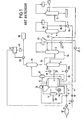
- acetic acid is prepared by carbonylation of methanol with carbon monoxide, in the liquid phase, in the presence of a homogeneous catalytic system, in an installation shown schematically in FIG.
- the carbonylation reaction is carried out at a temperature of 185 ° C. under a total pressure of 29 bar absolute.
- the water concentration is maintained at a value of 14% by weight in the reaction medium.
- the plant comprises a reaction zone I consisting essentially of a reactor 1, a flash zone II essentially comprising a flash device 2 and a purification zone III comprising, in the case represented in this figure, three distillation columns 3 , 4 and 5.
- the carbon monoxide is supplied after purification in a liquid methane cryogenic separation system (not shown in the figure).
- the carbon monoxide is then introduced to the bottom of the reactor 1 via a pipe 7 provided with a flow meter 9 and an inlet valve 11.
- a carbon monoxide buffer tank 12 placed upstream of the Inlet valve 11 allows, if necessary, to dampen variations in the CO input flow rate in reactor 1.
- the methanol is also introduced to the bottom of the reactor 1 via a pipe 6 provided with a flow meter 8 and an inlet valve 10.
- a pressure switch 13 connected to the inlet valve 11 of the carbon monoxide makes it possible to control the total pressure in the reactor 1.
- the temperature in the reactor 1 is measured by a thermometric device 14 and can be modified by circulating a fraction of the reaction liquid in a cooling loop passing through a heat exchanger 15 supplied with a cooling fluid via a valve 30.
- reaction material stream thus withdrawn from the reactor, then cooled and recycled, removes about 20% of the heat of formation reaction of acetic acid.
- vents exit through a pipe 16 of the upper part of the reactor 1.
- the flow of gas purged at the top of the reactor 1 is adjusted so as to maintain a partial pressure of carbon monoxide of 10 bar in the gaseous atmosphere of the reactor.
- vents are then introduced into a gas-liquid separator 17 which returns the liquid part in the reactor 1 and the gaseous part to a washing column 19 in which the gas is washed with acetic acid or methanol before being discharged into the atmosphere after passing through a torch 18.
- the analyzer 21 can be any device for measuring the content of the purge gases, in particular hydrogen and / or CO 2 , continuously or sequentially.
- the selectivities are thus accessed by relating, in the calculation module 21 ', these partial flows to the total flow rate of carbon monoxide entering the reactor 1.
- This control can be carried out by any means conventionally used to control the level of a liquid in a reactor, in particular by means of a differential pressure measurement in a reactor reference leg system, represented at 37.
- a fraction of the liquid constituting the reaction medium is continuously transferred via a pipe 31 from the reactor 1 to the flash device 2 in which the pressure is maintained at a value lower than that which prevails in the reactor 1 so that a partial vaporization of the reaction liquid occurs.
- the flow F6 of the liquid introduced into the flash device 2 is measured by means of a flowmeter 22a.
- the non-vaporized fraction in the flash zone 2 returns to the reactor 1 via a line 32 and its flow rate F2 can be measured by means of a flow meter 22b.
- the fraction vaporized in the flash device 2 is sent to the first distillation column 3 via a line 33.
- the liquid collected at the base of this first distillation column is returned to the flash zone as shown by the reference 34, while a part of the aqueous liquid phase of the first column 3 is sent back to the reactor 1 through a separator 23 for decantation of the two liquid phases obtained with a flow rate F3 which can be measured by means of a flowmeter 24, the rest of the aqueous fraction being returned to the top of the first distillation column 3.
- the organic liquid phase from the top of the distillation column 3 is also recycled to the reactor with a flow F4 which can measured by means of a flow meter 25.
- the fraction freed from the heads and tails of column from column 3 is sent to a second distillation column 4, via a conduit 35.
- Part of the condensed liquid at the top of this second column 4 is recycled with a flow F5 to the reactor 1 through a conduit 36.
- the flow rate of this fraction can be measured via a flow meter 26.
- the remainder of the fraction head returns to column 4, as shown by mark 39.
- the fraction collected at the base of the second distillation column 4 consisting essentially of acetic acid, undergoes a final purification step in column 5 where the acetic acid is separated from the heavy by-products collected at the bottom of the column and lighter products collected at the top of the column and partially recycled to column 4.
- the carbon monoxide feed rate is subject to fluctuations related to production equipment located upstream.
- the flow rate of methanol is adjusted to the carbon monoxide flow rate in a quasi-stoichiometric manner.
- reaction liquid to the flash is then adjusted to remove the remaining calories from the reaction.
- the objective was then to give a fixed value to the temperature in order to stabilize the concentrations of the different species in the reactor, as well as the fluxes.
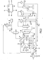
- the installation shown in FIG. 2 corresponds to an improvement of the installation shown in FIG. 1, incorporating a multivariable predictive regulator 40.
- the regulator 40 is programmed to regulate objective variables around setpoint values, by acting on action variables.
- the objective variables that one seeks to regulate are the input flow rate of carbon monoxide in reactor 1 and the CO 2 selectivity.
- the action variables are the temperature inside the reactor 1 and the methanol feed rate in this reactor.
- the regulation signals S1 and S2 are used to control, respectively, the methanol input flow rate control valve 10 in the reactor 1 and the control valve of the cooling fluid inlet flow rate in the heat exchanger. 15, so that the carbon monoxide flow rate and the CO 2 selectivity approach their CCO and CS setpoints.
- the set value CS around which the selectivity in CO 2 is regulated is a predetermined fixed value preferably chosen less than or equal to 0.01.
- the CCO setpoint around which the carbon monoxide flow rate is regulated varies with the availability of carbon monoxide in the CO 12 reservoir upstream of the reactor 1. This availability is apprehended directly by a measurement of the pressure P in the buffer tank 12 carried out by means of a pressure switch 38.
- the setpoint CCO is calculated by the regulator 40 as a function of the pressure P, which is applied to a fifth input E5 of the regulator, as shown in FIG.
- the slaving of the temperature in the reactor 1 and the methanol input flow rate in the same reactor at the carbon monoxide flow rate and the CO 2 selectivity, as described above, makes it possible to on the other hand, to maintain the CO 2 selectivity at a predetermined value, with consequent maintenance the concentration of methyl acetate.
- the regulator chosen as the regulator 40 is the IDCOM-HIECON device, which is a multivariable multivariable regulator by black box model intended for continuous manufacturing processes. It was developed by the company ADERSA.
- This regulator has been previously programmed as follows:
- a mathematical model of regulation was chosen from a library of known models known to the regulator using pre-recorded tests.
- Signals collected at the industrial site at a 5 second period were filtered by an anti-aliasing filter and were saved at the 2 minute period for identification.
- the temperature of the reactor 1 was rapidly incremented by 0.5 ° C; once the incrementation of the temperature was completed, the evolution of the parameters was monitored until a plateau was reached on the CO 2 selectivity and the carbon monoxide inlet flow rate (duration of about two hours).
- the temperature of the reactor was again rapidly increased by 0.5 ° C. and the monitoring of the parameters was carried out (duration approximately two hours).
- the monitoring of the parameters has more particularly consisted in continuously measuring the values of the variables of action (temperature in the reactor 1 and flow of methanol at the entry of this same reactor) and the values of objective variables (flow of carbon monoxide with reactor inlet 1 and CO 2 selectivity).
- the regulator was developed using the manufacturer supplied HIECON software. The measured values of the various parameters have been provided to the controller. The software then optimized the gain and delay parameters to be applied to the output signals S1 and S2.
- the CO 2 selectivity could be maintained within a small range of variations, while varying the temperature of the reaction mass and the methanol input flow rate. to be able to maximize the consumption of carbon monoxide and thus maximize the production of acetic acid.
- the introduction of the regulator has allowed to reduce to 0.5% the flow of CO in excess compared to the total flow of food CO, thus representing a gain in productivity of 1.5% of acetic acid over a representative period 5 months. This has increased the production of acetic acid by more than 2,000 tonnes over this 5-month period, compared to the same amount of CO available.
- the regulator 40 is used here to further slave the recycle streams to the reactor 1 at the liquid level in this reactor.
- the main liquid flow from the reactor is constituted by the flow rate from the reactor to the flash - F6 -.
- the stream F1 Since the stream F1 is already incorporated in the multivariable regulator, it suffices to add, as action variables, the streams F2, F3, F4, F5 and F6 respectively measured by the flow meters 22b, 24, 25, 26 and 22a, and as objective variable, the liquid level in the reactor 1, measured by the device 37.
- the new control objective relating to the liquid level in the reactor, can be obtained in different ways.
- Signals collected at the industrial site at a 5 second period were filtered by an anti-aliasing filter and were saved at the 2 minute period for identification.
- the positive or negative increments were 0.2 T / h for F1, 2 T / h for F2, 0.5 T / h for F4 and F5 and 15 T / h for F6.
- HIECON software was then used to optimize the control parameters.
- the carbonylation of methanol is conducted in a continuous pilot plant, which incorporates the operating principle of the industrial workshop, with a stirred reactor, a flash, the recycling of the liquid phase (containing the catalytic species) from the flash separator to the reactor.
- the distillation is not carried out and the recycling of the streams of zone III is simulated by introducing so-called new reagents (mixture of acetic acid, methyl acetate, methyl iodide and water); the catalyst lost by entrainment in the vapor phase of the flash separator is re-introduced periodically as a new catalyst in the reactor.
- new reagents mixture of acetic acid, methyl acetate, methyl iodide and water
- the total pressure is 35 bar, the reactor temperature is 190 ° C.
- the carbon monoxide partial pressure is 23 bar.
- the carbonylation rate is 15.5 moles / (h.l) under these conditions.
- the CO 2 selectivity is 0.01, the hydrogen selectivity is 0.001 and the methane selectivity 0.009.
- the main objective is not to optimize the use of available carbon monoxide, but to obtain sufficiently stable reaction and operating conditions to validate and optimize the use of available carbon monoxide. activity of the catalytic medium.
- the parameters of the rhodium catalysis pipe of example 2 can no longer be used: in fact the variation of the CO 2 selectivity is insensitive in the operating range chosen, and therefore does not allow to control the content of the methyl acetate.
- the low water content chemistry is very sensitive to the water content, which is a direct parameter of the kinetics of the acetic acid production reaction.
- a near infra-red spectrometry analyzer made it possible to determine in situ the contents of water, methyl acetate, methyl iodide and acetic acid in the reaction medium, with response times less than one minute.
- the analyzer set up is the 5000 model from NIRSystems.
- a mathematical model is then created to determine, in real time, the concentrations of the three main constituents selected: water, methyl acetate and methyl iodide.
- Signals collected at the industrial site at a 5 second period were filtered by an anti-aliasing filter and were saved at the 2 minute period for identification.
- the Hiecon software then made it possible to adapt the regulator to the problem.
Landscapes
- Chemical & Material Sciences (AREA)
- Organic Chemistry (AREA)
- Chemical Kinetics & Catalysis (AREA)
- Engineering & Computer Science (AREA)
- Oil, Petroleum & Natural Gas (AREA)
- Organic Low-Molecular-Weight Compounds And Preparation Thereof (AREA)
- Low-Molecular Organic Synthesis Reactions Using Catalysts (AREA)
Claims (18)
- Verfahren zur kontinuierlichen Herstellung von Essigsäure und/oder Methylacetat durch Carbonylierung durch Kohlenmonoxyd von Methanol oder einem carbonylierbaren Derivat von Methanol in Flüssigphase, in Gegenwart von Wasser und einem homogenen, katalytischen System, wobei das Herstellungsverfahren in einer industriellen Anlage ausgeführt wird, welche umfaßt:- eine Zone I, genannt Reaktionszone, umfassend einen Reaktor, in welchem eine Carbonylierungsreaktion des Methanols in Flüssigphase ausgeführt wird, bei einer Temperatur von 150 bis 250°C unter einem Druck von 5 x 10⁵ bis 200 x 105 Pa und mit Entfernung von einem gasförmigen Kopfteil über dem Flüssigkeitspegel des Reaktionsmediums in dem Reaktor in Form von Abzugsöffnungen,- eine Zone II, genannt Verdampfungszone oder Flashzone, wo die Flüssigkeit aus dem Reaktionsmedium der Zone I partiell bei einem Druck unterhalb von jenem der Zone I verdampft wird, wobei die Flüssigfraktion aus dieser partiellen Verdampfung zum Reaktor rezykliert wird,- eine Zone III, genannt Reinigungszone durch Destillation der verdampften Fraktion aus der Flashzone II auf einer oder mehreren Destillationskolonnen, an deren Ausgang Essigsäure und/oder Methylacetat gewonnen wird, wobei die anderen Bestandteile der verdampften Fraktion wenigstens teilweise zu dem Reaktor rezykliert werden,dadurch kennzeichnet, daß im Hinblick auf die Verbesserung der Regelung der Produktion von Essigsäure und/oder Methylacetat die Temperatur des Reaktors und der Eingangsdurchsatz des Methanols oder des carbonylierbaren Derivats in den Reaktor dem Eingangsdurchsatz von Kohlenmonoxid und wenigstens einem der Parameter unterworfen werden, die die Zusammensetzung des Reaktionsmediums definieren und/oder die Abzugsöffnungen.
- Verfahren nach Anspruch 1, dadurch gekennzeichnet, daß die Unterwerfung mittels einer mehrfach variablen Vorhersagesteuerung durchgeführt wird.
- Verfahren nach Anspruch 1 oder 2, dadurch gekennzeichnet, daß es ausgeführt wird, in dem die Wasserkonzentration im Reaktionsmedium bei einem Wert oberhalb von 14 Gew.-% gehalten wird.
- Verfahren nach Anspruch 3, dadurch gekennzeichnet, daß die Temperatur des Reaktors und der Eingangsdurchsatz des Methanols dem Eingangsdurchsatz von Kohlenmonoxid unterworfen werden und die Selektivität an H2 oder CO2 bei einem Wert unterhalb oder gleich 0,01 gehalten wird und/oder die Konzentration an Methylacetat bei einem Wert unter 5 Gew.-%, vorzugsweise unter 2 Gew.-% im Verhältnis zum Reaktionsmedium gehalten wird.
- Verfahren nach Anspruch 1 oder 2, dadurch gekennzeichnet, daß es unter Aufrechterhaltung der Wasserkonzentration in dem Reaktionsmedium bei einem Wert unter 14 Gew.-% im Verhältnis zum Gewicht des Reaktionsmediums ausgeführt wird.
- Verfahren nach Anspruch 5, dadurch gekennzeichnet, daß die Temperatur des Reaktors und der Eingangsdurchsatz von Methanol oder carbonylierbaren Derivat in dem Reaktor dem Eingangsdurchsatz von Kohlenmonoxid und der Wasserkonzentration im Reaktionsmedium unterworfen werden, wobei die Konzentration auf einem vorbestimmten Sollwert gehalten wird.
- Verfahren nach Anspruch 1 bis 6, dadurch gekennzeichnet, daß der Flüssigdurchsatz des Reaktors zur Flashzone II und die Flüssigrezyklierungsdurchsätze der Zonen II und III in dem Reaktor im übrigen dem Niveau der Flüssigkeit in dem Reaktor derart unterworfen werden, daß der Pegel auf einem vorbestimmten Wert festgelegt bleibt.
- Verfahren nach einem der Ansprüche 1 bis 7, dadurch gekennzeichnet, daß man die Wasserkonzentration im Reaktionsmedium kontrolliert und reguliert.
- Verfahren nach einem der Ansprüche 1 bis 8, dadurch gekennzeichnet, daß man die Variationen des Eingangsdurchsatzes von Kohlenmonoxid mittels eines Puffertanks dämpft, der dem Reaktor vorgelagert ist.
- Verfahren nach Anspruch 9, dadurch gekennzeichnet, daß man einen Sollwert des Durchsatzes von Kohlenmonoxid von dem Druck in dem Puffertank abhängen läßt.
- Verfahren nach einem der Ansprüche 1 bis 10, dadurch gekennzeichnet, daß man die Fluktuationen des Durchsatzes von Kohlenmonoxid, das in den Reaktor eintritt, dämpft, indem man wenigstens einen Teil des überschüssigen Durchsatzes in die Atmosphäre ausstößt.
- Verfahren nach einem der Ansprüche 1 bis 11, dadurch gekennzeichnet, daß ein Teil der Kalorien der Reaktion zur Herstellung von Essigsäure beseitigt oder rückgewonnen wird.
- Verfahren nach einem der Ansprüche 1 bis 12, dadurch gekennzeichnet, daß man die Konzentrationen an Wasser und an Methylacetat mit einem Analysator mißt, der im Nahinfrarotbereich arbeitet.
- Verfahren nach einem der Ansprüche 1 bis 13, dadurch gekennzeichnet, daß das in dem Verfahren zur Herstellung von Essigsäure und/oder Methylacetat eingesetzte katalytische System wenigstens ein Metall der Gruppe VIII umfaßt, insbesondere Rhodium, Iridium oder Platin.
- Verfahren nach Anspruch 14, dadurch gekennzeichnet, daß das katalytische System im übrigen wenigstens einen Co-Katalysator umfaßt.
- Verfahren nach Anspruch 15, dadurch gekennzeichnet, daß der Co-Katalysator Methyliodid ist.
- Verfahren nach Anspruch 16, dadurch gekennzeichnet, daß man die Konzentrationen an Wasser und Methylacetat und/oder Methyliodid mittels eines Analysators mißt, der im Nahinfrarotbereich arbeitet.
- Verfahren nach einem der Ansprüche 1 bis 17, dadurch gekennzeichnet, daß es auf eine Herstellung von Essigsäure und/oder Methylacetat durch Carbonylierung von Methanol angewandt wird.
Applications Claiming Priority (3)
| Application Number | Priority Date | Filing Date | Title |
|---|---|---|---|
| FR0108798 | 2001-07-03 | ||
| FR0108798A FR2826960B1 (fr) | 2001-07-03 | 2001-07-03 | Procede de controle d'une production d'acide acetique et/ou d'acetate de methyle en continu |
| PCT/FR2002/002212 WO2003004449A1 (fr) | 2001-07-03 | 2002-06-26 | Perfectionnement aux procedes de fabrication d'acide acetique et/ou d'acetate de methyle en continu |
Publications (2)
| Publication Number | Publication Date |
|---|---|
| EP1409444A1 EP1409444A1 (de) | 2004-04-21 |
| EP1409444B1 true EP1409444B1 (de) | 2006-11-02 |
Family
ID=8865058
Family Applications (1)
| Application Number | Title | Priority Date | Filing Date |
|---|---|---|---|
| EP02762492A Expired - Lifetime EP1409444B1 (de) | 2001-07-03 | 2002-06-26 | Verbesserte verfahren zur kontinuierlichen herstellung von essigsäure und/oder essigsäuremethylester |
Country Status (22)
| Country | Link |
|---|---|
| US (1) | US6642413B2 (de) |
| EP (1) | EP1409444B1 (de) |
| JP (1) | JP4091541B2 (de) |
| KR (1) | KR100954305B1 (de) |
| CN (1) | CN1321966C (de) |
| AT (1) | ATE344224T1 (de) |
| AU (1) | AU2002327872B2 (de) |
| CA (1) | CA2452258A1 (de) |
| CY (1) | CY1105938T1 (de) |
| DE (1) | DE60215817T2 (de) |
| DK (1) | DK1409444T3 (de) |
| ES (1) | ES2274998T3 (de) |
| FR (1) | FR2826960B1 (de) |
| MY (1) | MY122939A (de) |
| NZ (1) | NZ530275A (de) |
| OA (1) | OA12642A (de) |
| PT (1) | PT1409444E (de) |
| RU (1) | RU2282614C2 (de) |
| SA (1) | SA02230229B1 (de) |
| TW (1) | TW588039B (de) |
| UA (1) | UA76469C2 (de) |
| WO (1) | WO2003004449A1 (de) |
Families Citing this family (25)
| Publication number | Priority date | Publication date | Assignee | Title |
|---|---|---|---|---|
| CN100430363C (zh) * | 2003-10-30 | 2008-11-05 | 上海吴泾化工有限公司 | 一种羰基化生产醋酸的改进方法及其装置 |
| CA2496839A1 (en) | 2004-07-19 | 2006-01-19 | Woodland Chemical Systems Inc. | Process for producing ethanol from synthesis gas rich in carbon monoxide |
| US7767848B2 (en) * | 2005-02-08 | 2010-08-03 | Celanese International Corporation | Method of controlling acetic acid process |
| ES2539761T3 (es) | 2006-04-05 | 2015-07-03 | Woodland Biofuels Inc. | Sistema y método para convertir biomasa en etanol a través del gas de síntesis |
| US7989659B2 (en) * | 2007-05-17 | 2011-08-02 | Celanese International Corporation | Method and apparatus for making acetic acid with improved light ends column productivity |
| JP2009062289A (ja) * | 2007-09-04 | 2009-03-26 | Nippon Shokubai Co Ltd | アクリル酸及び(メタ)アクリル酸エステルの製造方法 |
| US7619113B2 (en) * | 2007-09-27 | 2009-11-17 | Celanese International Corporation | Method and apparatus for making acetic acid with improved purification |
| US7902397B2 (en) * | 2007-10-11 | 2011-03-08 | Celanese International Corporation | Method and apparatus for making acetic acid with improved productivity |
| BRPI0910840B1 (pt) * | 2008-04-29 | 2018-05-08 | Celanese International Corporation | aparelho para produção de ácido acético, método de operação de uma torre absorvedora em uma unidade de carbonilação e método aperfeiçoado para operação de um aparelho para fabricação de ácido acético |
| FR2946659B1 (fr) * | 2009-06-10 | 2011-07-01 | Inst Francais Du Petrole | Methode pour optimiser le fonctionnement d'une unite de synthese d'hydrocarbures a partir de gaz de synthese par controle de la pression partielle en co |
| US8168822B2 (en) * | 2009-07-07 | 2012-05-01 | Celanese International Corporation | Acetic acid production by way of carbonylation with enhanced reaction and flashing |
| KR101747484B1 (ko) | 2010-07-26 | 2017-06-14 | 주식회사 다이셀 | 아세트산의 제조 방법 |
| US8530696B2 (en) * | 2010-09-24 | 2013-09-10 | Celanese International Corporation | Pump around reactor for production of acetic acid |
| US8461379B2 (en) * | 2010-10-12 | 2013-06-11 | Celanese International Corporation | Production of acetic acid comprising feeding at least one reactant to a recycle stream |
| CN103189125A (zh) * | 2010-11-12 | 2013-07-03 | 伊士曼化工公司 | 羰基化过程产生的气流的处理 |
| CN102381956B (zh) * | 2011-09-06 | 2013-08-21 | 安徽皖维高新材料股份有限公司 | 醋酸甲酯和甲醇共沸物羰基合成醋酐、醋酸及分离方法 |
| US10585077B2 (en) * | 2015-04-10 | 2020-03-10 | Waters Technologies Corporation | Cooling liquid eluent of a carbon dioxide chromatography system after gas-liquid separation |
| CN106397203B (zh) * | 2016-08-19 | 2019-05-07 | 安徽皖维高新材料股份有限公司 | 一种稳定控制醋酸甲酯精制变压精馏工艺中加压精馏塔顶部压力的方法 |
| CN106365977A (zh) * | 2016-11-15 | 2017-02-01 | 广西新天德能源有限公司 | 一种抗磨耐腐蚀醋酸生产装置 |
| US10807935B2 (en) | 2018-11-02 | 2020-10-20 | Celanese International Corporation | Process for continuous acetic acid production |
| CN112574021A (zh) * | 2019-09-12 | 2021-03-30 | 南京延长反应技术研究院有限公司 | 一种强化羰基化反应系统及工艺 |
| CN113600109B (zh) * | 2021-08-17 | 2023-07-25 | 江苏索普工程科技有限公司 | 一种甲醇羰基化制醋酸微界面反应系统及方法 |
| EP4148035A1 (de) * | 2021-09-14 | 2023-03-15 | Air Liquide Societe Anonyme pour l'Etude et L'Exploitation des procedes Georges Claude | Methanolsynthese auf basis eines mathematischen modells |
| CN117930897B (zh) * | 2024-01-25 | 2024-06-25 | 山东中科绿碳科技有限公司 | 一种用于食品级碳酸氢铵工艺的智能监测系统 |
| CN119617302B (zh) * | 2025-02-17 | 2025-05-13 | 安徽碳鑫科技有限公司 | 一种以co为载气的节能型二甲醚高效汽化混合方法 |
Family Cites Families (11)
| Publication number | Priority date | Publication date | Assignee | Title |
|---|---|---|---|---|
| GB1002785A (en) * | 1963-07-24 | 1965-08-25 | Coley Bros Tools Ltd | Lubricator for rectilinear bearings |
| CA1228867A (en) * | 1984-05-03 | 1987-11-03 | Celanese Corporation | Methanol carbonylation process |
| ZA853339B (en) * | 1984-05-03 | 1985-12-24 | Celanese Corp | Methanol carbonylation process |
| CN1014407B (zh) * | 1985-02-08 | 1991-10-23 | 赛拉尼斯公司 | 改进的甲醇羰基化方法 |
| US5352415A (en) * | 1993-09-29 | 1994-10-04 | Hoechst Celanese Corporation | Control system for acetic acid manufacturing process |
| US5374774A (en) | 1994-03-11 | 1994-12-20 | Hoechst Celanese Corporation | Control system for an acetic acid manufacturing process |
| US5604132A (en) * | 1995-01-23 | 1997-02-18 | Olin Corporation | Process flow injection analyzer and method |
| GB9512427D0 (en) * | 1995-06-19 | 1995-08-23 | Bp Chem Int Ltd | Process |
| GB9819079D0 (en) * | 1998-09-03 | 1998-10-28 | Bp Chem Int Ltd | Carbonylation process |
| GB9825424D0 (en) * | 1998-11-19 | 1999-01-13 | Bp Chem Int Ltd | Process |
| US6552221B1 (en) * | 1998-12-18 | 2003-04-22 | Millenium Petrochemicals, Inc. | Process control for acetic acid manufacture |
-
2001
- 2001-07-03 FR FR0108798A patent/FR2826960B1/fr not_active Expired - Fee Related
- 2001-09-13 US US09/950,819 patent/US6642413B2/en not_active Expired - Fee Related
-
2002
- 2002-06-26 OA OA1200300349A patent/OA12642A/fr unknown
- 2002-06-26 PT PT02762492T patent/PT1409444E/pt unknown
- 2002-06-26 CA CA002452258A patent/CA2452258A1/en not_active Abandoned
- 2002-06-26 AT AT02762492T patent/ATE344224T1/de active
- 2002-06-26 JP JP2003510417A patent/JP4091541B2/ja not_active Expired - Fee Related
- 2002-06-26 AU AU2002327872A patent/AU2002327872B2/en not_active Ceased
- 2002-06-26 DE DE60215817T patent/DE60215817T2/de not_active Expired - Lifetime
- 2002-06-26 EP EP02762492A patent/EP1409444B1/de not_active Expired - Lifetime
- 2002-06-26 RU RU2003137581/04A patent/RU2282614C2/ru not_active IP Right Cessation
- 2002-06-26 ES ES02762492T patent/ES2274998T3/es not_active Expired - Lifetime
- 2002-06-26 CN CNB028152646A patent/CN1321966C/zh not_active Expired - Fee Related
- 2002-06-26 KR KR1020037017285A patent/KR100954305B1/ko not_active Expired - Fee Related
- 2002-06-26 UA UA20031212330A patent/UA76469C2/uk unknown
- 2002-06-26 NZ NZ530275A patent/NZ530275A/en not_active IP Right Cessation
- 2002-06-26 WO PCT/FR2002/002212 patent/WO2003004449A1/fr not_active Ceased
- 2002-06-26 DK DK02762492T patent/DK1409444T3/da active
- 2002-07-03 TW TW091114711A patent/TW588039B/zh active
- 2002-07-03 MY MYPI20022509A patent/MY122939A/en unknown
- 2002-07-31 SA SA02230229A patent/SA02230229B1/ar unknown
-
2007
- 2007-01-18 CY CY20071100073T patent/CY1105938T1/el unknown
Also Published As
| Publication number | Publication date |
|---|---|
| TW588039B (en) | 2004-05-21 |
| PT1409444E (pt) | 2007-01-31 |
| FR2826960A1 (fr) | 2003-01-10 |
| CY1105938T1 (el) | 2011-04-06 |
| CA2452258A1 (en) | 2003-01-16 |
| DE60215817T2 (de) | 2007-08-30 |
| EP1409444A1 (de) | 2004-04-21 |
| RU2282614C2 (ru) | 2006-08-27 |
| OA12642A (fr) | 2006-06-16 |
| AU2002327872B2 (en) | 2007-03-22 |
| MY122939A (en) | 2006-05-31 |
| RU2003137581A (ru) | 2005-05-20 |
| UA76469C2 (en) | 2006-08-15 |
| NZ530275A (en) | 2005-03-24 |
| SA02230229B1 (ar) | 2007-02-27 |
| ES2274998T3 (es) | 2007-06-01 |
| DK1409444T3 (da) | 2007-03-05 |
| ATE344224T1 (de) | 2006-11-15 |
| CN1321966C (zh) | 2007-06-20 |
| KR20040020955A (ko) | 2004-03-09 |
| US6642413B2 (en) | 2003-11-04 |
| JP4091541B2 (ja) | 2008-05-28 |
| DE60215817D1 (de) | 2006-12-14 |
| US20030018213A1 (en) | 2003-01-23 |
| CN1538947A (zh) | 2004-10-20 |
| KR100954305B1 (ko) | 2010-04-21 |
| FR2826960B1 (fr) | 2005-10-21 |
| JP2004533478A (ja) | 2004-11-04 |
| WO2003004449A1 (fr) | 2003-01-16 |
Similar Documents
| Publication | Publication Date | Title |
|---|---|---|
| EP1409444A1 (de) | Verbesserte verfahren zur kontinuierlichen herstellung von essigsäure und/oder essigsäuremethylester | |
| CN1244533C (zh) | 用于乙酸制备的过程控制 | |
| CA1069536A (fr) | Procede de fabrication de l'aldehyde beta-methylthiopropionique | |
| EP2630471B1 (de) | Verfahren zur herstellung von essigsäure | |
| KR101465806B1 (ko) | 아세트산 제조 방법 | |
| US6677480B2 (en) | Process control in production of acetic acid via use of heavy phase density measurement | |
| FR2734495A1 (fr) | Procede de recuperation de monoxyde de carbone a partir de gaz de purge de la synthese de l'acide acetique a faible teneur en co,n2,et h2 | |
| AU4341299A (en) | Acetic acid reactive distillation process based on DME/methanlol carbonylation | |
| KR101740091B1 (ko) | 아세트산 제조 공정의 디켄터 상분리 제어 | |
| FR2916039A1 (fr) | Procede de regulation d'une unite de distillation cryogenique. | |
| WO2000078700A2 (fr) | Procede pour ameliorer la stabilite et/ou eviter la desactivation du catalyseur lors de la fabrication d'acide acetique et/ou d'acetate de methyle | |
| FR2897860A1 (fr) | Procede d'optimisation de la marche des unites claus. | |
| BE841236A (fr) | Procede de reglage de l'activite catalytique dans un procede de conversion d'un alcene en un derive carbonyle | |
| KR20140097597A (ko) | 아세트산 제조 방법 |
Legal Events
| Date | Code | Title | Description |
|---|---|---|---|
| PUAI | Public reference made under article 153(3) epc to a published international application that has entered the european phase |
Free format text: ORIGINAL CODE: 0009012 |
|
| 17P | Request for examination filed |
Effective date: 20040112 |
|
| AK | Designated contracting states |
Kind code of ref document: A1 Designated state(s): AT BE CH CY DE DK ES FI FR GB GR IE IT LI LU MC NL PT SE TR |
|
| AX | Request for extension of the european patent |
Extension state: AL LT LV MK RO SI |
|
| GRAP | Despatch of communication of intention to grant a patent |
Free format text: ORIGINAL CODE: EPIDOSNIGR1 |
|
| GRAS | Grant fee paid |
Free format text: ORIGINAL CODE: EPIDOSNIGR3 |
|
| GRAA | (expected) grant |
Free format text: ORIGINAL CODE: 0009210 |
|
| AK | Designated contracting states |
Kind code of ref document: B1 Designated state(s): AT BE CH CY DE DK ES FI FR GB GR IE IT LI LU MC NL PT SE TR |
|
| REG | Reference to a national code |
Ref country code: GB Ref legal event code: FG4D Free format text: NOT ENGLISH |
|
| REG | Reference to a national code |
Ref country code: IE Ref legal event code: FG4D Free format text: LANGUAGE OF EP DOCUMENT: FRENCH |
|
| REG | Reference to a national code |
Ref country code: CH Ref legal event code: EP |
|
| REF | Corresponds to: |
Ref document number: 60215817 Country of ref document: DE Date of ref document: 20061214 Kind code of ref document: P |
|
| REG | Reference to a national code |
Ref country code: PT Ref legal event code: SC4A Free format text: AVAILABILITY OF NATIONAL TRANSLATION Effective date: 20070111 |
|
| GBT | Gb: translation of ep patent filed (gb section 77(6)(a)/1977) |
Effective date: 20070116 |
|
| REG | Reference to a national code |
Ref country code: SE Ref legal event code: TRGR |
|
| REG | Reference to a national code |
Ref country code: CH Ref legal event code: NV Representative=s name: BOVARD AG PATENTANWAELTE |
|
| REG | Reference to a national code |
Ref country code: DK Ref legal event code: T3 |
|
| REG | Reference to a national code |
Ref country code: GR Ref legal event code: EP Ref document number: 20070400360 Country of ref document: GR |
|
| REG | Reference to a national code |
Ref country code: ES Ref legal event code: FG2A Ref document number: 2274998 Country of ref document: ES Kind code of ref document: T3 |
|
| PLBE | No opposition filed within time limit |
Free format text: ORIGINAL CODE: 0009261 |
|
| STAA | Information on the status of an ep patent application or granted ep patent |
Free format text: STATUS: NO OPPOSITION FILED WITHIN TIME LIMIT |
|
| 26N | No opposition filed |
Effective date: 20070803 |
|
| REG | Reference to a national code |
Ref country code: FR Ref legal event code: ST Effective date: 20080229 |
|
| PG25 | Lapsed in a contracting state [announced via postgrant information from national office to epo] |
Ref country code: FR Free format text: LAPSE BECAUSE OF NON-PAYMENT OF DUE FEES Effective date: 20070702 |
|
| PG25 | Lapsed in a contracting state [announced via postgrant information from national office to epo] |
Ref country code: CY Free format text: LAPSE BECAUSE OF NON-PAYMENT OF DUE FEES Effective date: 20090626 |
|
| REG | Reference to a national code |
Ref country code: CH Ref legal event code: PFA Owner name: ACETEX CHIMIE Free format text: ACETEX CHIMIE#164 BIS, AVENUE DU GENERAL DE GAULLE#92205 NEUILLY-SUR-SEINE (FR) -TRANSFER TO- ACETEX CHIMIE#164 BIS, AVENUE DU GENERAL DE GAULLE#92205 NEUILLY-SUR-SEINE (FR) |
|
| PGFP | Annual fee paid to national office [announced via postgrant information from national office to epo] |
Ref country code: LU Payment date: 20110621 Year of fee payment: 10 |
|
| PGFP | Annual fee paid to national office [announced via postgrant information from national office to epo] |
Ref country code: CY Payment date: 20110530 Year of fee payment: 10 |
|
| PGFP | Annual fee paid to national office [announced via postgrant information from national office to epo] |
Ref country code: CH Payment date: 20120612 Year of fee payment: 11 Ref country code: DE Payment date: 20120620 Year of fee payment: 11 Ref country code: TR Payment date: 20120522 Year of fee payment: 11 Ref country code: IE Payment date: 20120612 Year of fee payment: 11 Ref country code: NL Payment date: 20120614 Year of fee payment: 11 Ref country code: MC Payment date: 20120528 Year of fee payment: 11 Ref country code: DK Payment date: 20120612 Year of fee payment: 11 |
|
| PGFP | Annual fee paid to national office [announced via postgrant information from national office to epo] |
Ref country code: GB Payment date: 20120620 Year of fee payment: 11 Ref country code: SE Payment date: 20120612 Year of fee payment: 11 Ref country code: GR Payment date: 20120521 Year of fee payment: 11 Ref country code: FI Payment date: 20120612 Year of fee payment: 11 |
|
| PGFP | Annual fee paid to national office [announced via postgrant information from national office to epo] |
Ref country code: IT Payment date: 20120620 Year of fee payment: 11 |
|
| PGFP | Annual fee paid to national office [announced via postgrant information from national office to epo] |
Ref country code: BE Payment date: 20120620 Year of fee payment: 11 |
|
| PGFP | Annual fee paid to national office [announced via postgrant information from national office to epo] |
Ref country code: ES Payment date: 20120726 Year of fee payment: 11 |
|
| PGFP | Annual fee paid to national office [announced via postgrant information from national office to epo] |
Ref country code: PT Payment date: 20111227 Year of fee payment: 11 |
|
| PGFP | Annual fee paid to national office [announced via postgrant information from national office to epo] |
Ref country code: AT Payment date: 20120529 Year of fee payment: 11 |
|
| BERE | Be: lapsed |
Owner name: ACETEX CHIMIE Effective date: 20130630 |
|
| REG | Reference to a national code |
Ref country code: PT Ref legal event code: MM4A Free format text: LAPSE DUE TO NON-PAYMENT OF FEES Effective date: 20131226 |
|
| REG | Reference to a national code |
Ref country code: NL Ref legal event code: V1 Effective date: 20140101 |
|
| PG25 | Lapsed in a contracting state [announced via postgrant information from national office to epo] |
Ref country code: SE Free format text: LAPSE BECAUSE OF NON-PAYMENT OF DUE FEES Effective date: 20130627 Ref country code: CY Free format text: LAPSE BECAUSE OF FAILURE TO SUBMIT A TRANSLATION OF THE DESCRIPTION OR TO PAY THE FEE WITHIN THE PRESCRIBED TIME-LIMIT Effective date: 20130703 Ref country code: PT Free format text: LAPSE BECAUSE OF NON-PAYMENT OF DUE FEES Effective date: 20131226 Ref country code: MC Free format text: LAPSE BECAUSE OF NON-PAYMENT OF DUE FEES Effective date: 20130701 |
|
| REG | Reference to a national code |
Ref country code: CH Ref legal event code: PL |
|
| REG | Reference to a national code |
Ref country code: SE Ref legal event code: EUG |
|
| REG | Reference to a national code |
Ref country code: DK Ref legal event code: EBP Effective date: 20130630 |
|
| REG | Reference to a national code |
Ref country code: AT Ref legal event code: MM01 Ref document number: 344224 Country of ref document: AT Kind code of ref document: T Effective date: 20130626 |
|
| GBPC | Gb: european patent ceased through non-payment of renewal fee |
Effective date: 20130626 |
|
| REG | Reference to a national code |
Ref country code: GR Ref legal event code: ML Ref document number: 20070400360 Country of ref document: GR Effective date: 20140103 |
|
| PG25 | Lapsed in a contracting state [announced via postgrant information from national office to epo] |
Ref country code: FI Free format text: LAPSE BECAUSE OF NON-PAYMENT OF DUE FEES Effective date: 20130626 |
|
| REG | Reference to a national code |
Ref country code: IE Ref legal event code: MM4A |
|
| REG | Reference to a national code |
Ref country code: DE Ref legal event code: R119 Ref document number: 60215817 Country of ref document: DE Effective date: 20140101 |
|
| PG25 | Lapsed in a contracting state [announced via postgrant information from national office to epo] |
Ref country code: CY Free format text: LAPSE BECAUSE OF FAILURE TO SUBMIT A TRANSLATION OF THE DESCRIPTION OR TO PAY THE FEE WITHIN THE PRESCRIBED TIME-LIMIT Effective date: 20130626 Ref country code: BE Free format text: LAPSE BECAUSE OF NON-PAYMENT OF DUE FEES Effective date: 20130630 |
|
| PG25 | Lapsed in a contracting state [announced via postgrant information from national office to epo] |
Ref country code: CH Free format text: LAPSE BECAUSE OF NON-PAYMENT OF DUE FEES Effective date: 20130630 Ref country code: GB Free format text: LAPSE BECAUSE OF NON-PAYMENT OF DUE FEES Effective date: 20130626 Ref country code: NL Free format text: LAPSE BECAUSE OF NON-PAYMENT OF DUE FEES Effective date: 20140101 Ref country code: LI Free format text: LAPSE BECAUSE OF NON-PAYMENT OF DUE FEES Effective date: 20130630 Ref country code: IE Free format text: LAPSE BECAUSE OF NON-PAYMENT OF DUE FEES Effective date: 20130626 Ref country code: DE Free format text: LAPSE BECAUSE OF NON-PAYMENT OF DUE FEES Effective date: 20140101 |
|
| PG25 | Lapsed in a contracting state [announced via postgrant information from national office to epo] |
Ref country code: AT Free format text: LAPSE BECAUSE OF NON-PAYMENT OF DUE FEES Effective date: 20130626 Ref country code: GR Free format text: LAPSE BECAUSE OF NON-PAYMENT OF DUE FEES Effective date: 20140103 Ref country code: IT Free format text: LAPSE BECAUSE OF NON-PAYMENT OF DUE FEES Effective date: 20130626 |
|
| REG | Reference to a national code |
Ref country code: ES Ref legal event code: FD2A Effective date: 20140707 |
|
| PG25 | Lapsed in a contracting state [announced via postgrant information from national office to epo] |
Ref country code: DK Free format text: LAPSE BECAUSE OF NON-PAYMENT OF DUE FEES Effective date: 20130630 |
|
| PG25 | Lapsed in a contracting state [announced via postgrant information from national office to epo] |
Ref country code: ES Free format text: LAPSE BECAUSE OF NON-PAYMENT OF DUE FEES Effective date: 20130627 |
|
| PG25 | Lapsed in a contracting state [announced via postgrant information from national office to epo] |
Ref country code: LU Free format text: LAPSE BECAUSE OF NON-PAYMENT OF DUE FEES Effective date: 20130626 |
|
| PG25 | Lapsed in a contracting state [announced via postgrant information from national office to epo] |
Ref country code: TR Free format text: LAPSE BECAUSE OF NON-PAYMENT OF DUE FEES Effective date: 20130626 |