EP1410937A1 - Structure de support d'une unite de dispositif de disque - Google Patents
Structure de support d'une unite de dispositif de disque Download PDFInfo
- Publication number
- EP1410937A1 EP1410937A1 EP01947870A EP01947870A EP1410937A1 EP 1410937 A1 EP1410937 A1 EP 1410937A1 EP 01947870 A EP01947870 A EP 01947870A EP 01947870 A EP01947870 A EP 01947870A EP 1410937 A1 EP1410937 A1 EP 1410937A1
- Authority
- EP
- European Patent Office
- Prior art keywords
- mount
- drive unit
- support structure
- mounts
- hand
- Prior art date
- Legal status (The legal status is an assumption and is not a legal conclusion. Google has not performed a legal analysis and makes no representation as to the accuracy of the status listed.)
- Granted
Links
Images



Classifications
-
- F—MECHANICAL ENGINEERING; LIGHTING; HEATING; WEAPONS; BLASTING
- F16—ENGINEERING ELEMENTS AND UNITS; GENERAL MEASURES FOR PRODUCING AND MAINTAINING EFFECTIVE FUNCTIONING OF MACHINES OR INSTALLATIONS; THERMAL INSULATION IN GENERAL
- F16F—SPRINGS; SHOCK-ABSORBERS; MEANS FOR DAMPING VIBRATION
- F16F7/00—Vibration-dampers; Shock-absorbers
- F16F7/10—Vibration-dampers; Shock-absorbers using inertia effect
- F16F7/1028—Vibration-dampers; Shock-absorbers using inertia effect the inertia-producing means being a constituent part of the system which is to be damped
-
- B—PERFORMING OPERATIONS; TRANSPORTING
- B60—VEHICLES IN GENERAL
- B60K—ARRANGEMENT OR MOUNTING OF PROPULSION UNITS OR OF TRANSMISSIONS IN VEHICLES; ARRANGEMENT OR MOUNTING OF PLURAL DIVERSE PRIME-MOVERS IN VEHICLES; AUXILIARY DRIVES FOR VEHICLES; INSTRUMENTATION OR DASHBOARDS FOR VEHICLES; ARRANGEMENTS IN CONNECTION WITH COOLING, AIR INTAKE, GAS EXHAUST OR FUEL SUPPLY OF PROPULSION UNITS IN VEHICLES
- B60K5/00—Arrangement or mounting of internal-combustion or jet-propulsion units
- B60K5/12—Arrangement of engine supports
- B60K5/1208—Resilient supports
- B60K5/1216—Resilient supports characterised by the location of the supports relative to the motor or to each other
-
- F—MECHANICAL ENGINEERING; LIGHTING; HEATING; WEAPONS; BLASTING
- F16—ENGINEERING ELEMENTS AND UNITS; GENERAL MEASURES FOR PRODUCING AND MAINTAINING EFFECTIVE FUNCTIONING OF MACHINES OR INSTALLATIONS; THERMAL INSULATION IN GENERAL
- F16F—SPRINGS; SHOCK-ABSORBERS; MEANS FOR DAMPING VIBRATION
- F16F13/00—Units comprising springs of the non-fluid type as well as vibration-dampers, shock-absorbers, or fluid springs
- F16F13/04—Units comprising springs of the non-fluid type as well as vibration-dampers, shock-absorbers, or fluid springs comprising both a plastics spring and a damper, e.g. a friction damper
- F16F13/06—Units comprising springs of the non-fluid type as well as vibration-dampers, shock-absorbers, or fluid springs comprising both a plastics spring and a damper, e.g. a friction damper the damper being a fluid damper, e.g. the plastics spring not forming a part of the wall of the fluid chamber of the damper
- F16F13/08—Units comprising springs of the non-fluid type as well as vibration-dampers, shock-absorbers, or fluid springs comprising both a plastics spring and a damper, e.g. a friction damper the damper being a fluid damper, e.g. the plastics spring not forming a part of the wall of the fluid chamber of the damper the plastics spring forming at least a part of the wall of the fluid chamber of the damper
- F16F13/10—Units comprising springs of the non-fluid type as well as vibration-dampers, shock-absorbers, or fluid springs comprising both a plastics spring and a damper, e.g. a friction damper the damper being a fluid damper, e.g. the plastics spring not forming a part of the wall of the fluid chamber of the damper the plastics spring forming at least a part of the wall of the fluid chamber of the damper the wall being at least in part formed by a flexible membrane or the like
- F16F13/101—Units comprising springs of the non-fluid type as well as vibration-dampers, shock-absorbers, or fluid springs comprising both a plastics spring and a damper, e.g. a friction damper the damper being a fluid damper, e.g. the plastics spring not forming a part of the wall of the fluid chamber of the damper the plastics spring forming at least a part of the wall of the fluid chamber of the damper the wall being at least in part formed by a flexible membrane or the like characterised by buffering features or stoppers
-
- B—PERFORMING OPERATIONS; TRANSPORTING
- B60—VEHICLES IN GENERAL
- B60G—VEHICLE SUSPENSION ARRANGEMENTS
- B60G2202/00—Indexing codes relating to the type of spring, damper or actuator
- B60G2202/20—Type of damper
- B60G2202/25—Dynamic damper
Definitions
- This invention relates to a support structure for mounting and supporting a drive unit such as an automobile engine and the like on a vehicle body.
- a support structure for supporting a drive unit in automotive vehicles such as a passenger car, including an engine, a transmission, etc. on the vehicle body by means of vibration-proof mounts, there is known the one dependent on a so-called pendulum mount system, which supports the drive unit integrated in a transverse direction inside the vehicle body in a suspending manner at either lateral side thereof by means of two mounts disposed above a gravity center of the unit and further supports a lower portion of the unit with a torque support portion extending in the opposite direction to a running direction of the vehicle by connecting it to the vehicle body.
- the excitation generated by the exciter 40 corresponds to an uneven road surface upon running of the vehicle and uniformity of the tires 52.
- This excitation is transmitted to the vehicle body 51, which further oscillates a drive unit 50 such as an engine supported by means of two mounts 53, 54 within the vehicle body, and as a result of its antiresonance action, the vertical vibrations of the floor of the vehicle body 51 become larger.
- the vertical vibrations of the floor are large in a low frequency region, once falls in the vicinity of 8 ⁇ 10Hz by a damper effect due to the mass weight of the drive unit 50 and becomes larger in the vicinity of 13 ⁇ 15 Hz owing to the antiresonance of the unit 50, generating a peak.
- the vertical vibrations of the vehicle body 51 transmit from the feet to the body of a passenger and are responsible for deteriorating the riding comfort. Consequently, suppressing or diminishing the vertical vibrations of the floor, in particular that at a frequency of 15 Hz and its vicinity permits an improvement in riding comfort performance.
- the present inventors have noted the fact that because the two right-hand and left-hand mounts are disposed above the gravity center of the unit, it is possible to unbalance easily the vibrations of the engine by tuning the spring constants and positions of the mounts, and made various investigations into relations between characteristics of the mounts such as dynamic spring constant, loss factor, etc. and vertical vibrations of the floor.
- the inventors have found out that the ratio between vertical dynamic spring constants of the right-hand and left-hand mounts and besides the peak frequency of loss factor of the one liquid-enclosed type vibration-proof mount affect significantly the vertical vibrations of the floor, namely the riding comfort and that by setting these parameters in specified ranges, it is possible to suppress significantly vertical vibrations in a frequency band of 12 to 17 Hz of the floor.
- the present invention has been made on the basis of this finding.
- the invention provides a pendulum mount type of support structure for a drive unit integrated in a transverse direction in the vehicle body, which supports the drive unit at its right-hand and left-hand sides by means of two mounts disposed upwardly of a gravity center G of the unit in a suspending manner and further supports a lower part of the unit by means of a torque support portion extending in the opposite direction to a vehicle running direction by connecting it to the vehicle body.
- the coefficient C is 1.2 or less, a sufficient improvement in riding comfort will not be obtainable.
- the coefficient C is 1.9 and upwards, an adverse influence on acoustic vibration performance will be concerned about.
- the coefficient C is desired to be a variable less than 1.9.
- the dynamic spring constant K2 of the other mount is set as stated above in the relationship of the position of the gravity center G of the unit to the dynamic spring constant K1 of the one mount, whereby antiresonance by the right-hand and left-hand mounts to the vertical vibrations is suppressed.
- vibrations in a frequency band of 12 to 17 Hz higher than the frequency in the neighborhood of 8 ⁇ 10 Hz due to damper effect of the drive unit, notably vibrations in the frequency band around 15 Hz are effectively suppressed.
- the suppression effect is especially enhanced.
- the peak frequency PHz of loss factor in the vertical direction of the aforementioned liquid-filled vibration-proof mount be set to satisfy the following equation (b):
- (b) PHz 1 2 ⁇ K1 + K2 M ⁇ d where the symbol M stands for a mass of the drive unit, and the symbol d stands for a coefficient given by the mass M, etc. and is a variable ranging from 1.4 to 2.4.
- Fig. 1 and Fig. 2 show a model of a support structure of this invention, wherein the reference numeral 1 is a drive unit such as engine, etc., which is, inclusive of a transmission in addition to the engine, usually constructed by assembling in a casing and transversely mounted inside the vehicle body of an automobile.
- Fig. 1 is a view (front elevation) as viewed from the front side in the running direction of the vehicle.
- This drive unit 1 is supported by two mounts RH and LH disposed upwardly of a gravity center G of the unit at the right and left sides thereof in a suspending state and a lower part of the unit 1 is supported by a torque support portion Rr connected to the vehicle body through a torque rod 2 extending in the opposite direction of a running direction of the vehicle, thus constructing a support structure according to a pendulum mount system.
- Figs. 1 and 2 there are shown the one mount RH located at the right side relative to the running direction on the left of the figures and the other mount LH located at the left side relative to the running direction on the right of the figures.
- one of the two right-hand and left-hand mounts RH, LH for example, the mount RH remoter from the position of the gravity center G of the unit is of a liquid-enclosed vibration-proof device and the other mount LH closer to the gravity center G is of a solid vibration isolating device.
- Fig. 3 illustrates one example of a liquid-enclosed vibration-proof device used for the one mount RH.
- This vibration-proof device comprises an upper fitting 11 adapted to be fitted to the one of the drive unit and the vehicle body, a lower fitting 12 adapted to be fitted to the other, a generally truncated conical vibration-isolating base 13 made of rubber-like elastomer interconnecting these fittings 11, 12, a diaphragm 14 disposed to oppose the vibration-isolating base 13 on the fitting 12 side, a liquid chamber 15 formed between the vibration-isolating base 13 and the diaphragm 14, a partition 16 dividing the liquid chamber 15 into a main liquid chamber 15a and a subsidiary liquid chamber 15b, and an orifice 17 formed at an outer peripheral portion of the partition 16 to put the main liquid chamber 15a and the subsidiary liquid chamber 15b into communication with each other.
- the vibration-proof device thus constructed is adapted to exhibit a vibration damping function due to the fluidization effect of the liquid between both liquid chambers 15a, 15b through the orifice 17 and to exhibit a vibration isolating function due to the vibration-isolating base 13.
- the reference numeral 18 designates a stopper fitting restraining a large displacement.
- Another liquid-sealed vibration-proof devices of various structures can also be used.
- the aforementioned vibration-proof device it is possible to provide a rubber-like elastic membrane in the central area of the partition 16 in order to diminish the dynamic spring constant in a high frequency region.
- a double orifice type vibration-proof device in which two orifices communicating with the main liquid chamber and the subsidiary liquid chamber are provided inside the main body, or cylindrical type liquid-sealed vibration-proof device may also be used.
- a conventional type vibration-isolating device as shown in Fig. 4 which comprises an upper attachment fitting 21, a lower attachment fitting 22, and a solid rubber-like elastomer 23 interconnecting both fittings 21,22.
- the reference numbers 24, 25 designate a stopper portion restraining a large displacement.
- the mount LH is not limited to that as illustrated, but another various forms of vibration-isolating devices may be used.
- a liquid-sealed type of vibration-proof device may be used, as well.
- the dynamic spring constant in the vertical direction of the one mount RH of the aforesaid two right-hand and left-hand mounts is K1 and the dynamic spring constant in the vertical direction of the other mount LH is K2, and distances in the horizontally transverse directions of from a gravity center G of the unit 1 to the perpendicular positions from centers of the one and the other mounts RH, LH are L1 and L2, respectively, then the dynamic spring constant K2 of the other mount LH shall be set to satisfy equation (a) given below:
- the dynamic spring constant K1 in the vertical direction of the one liquid-sealed mount RH is in a range of 100 to 220 N/mm, more preferably in a range of 140 to 200 N/mm
- K2 is set to satisfy equation (a) given below, where the symbol C in equation (a) is a coefficient and a variable of 1.3 or upward, more preferably less than 1.9.
- K2 C ⁇ L1 L2
- the dynamic spring constant K1 of the one (usually right-hand side in the vehicle running direction) mount RH is 160 N/mm and the distances L1, L2 are 500 mm and 400 mm, respectively
- the dynamic spring constant K2 of the other mount LH becomes 370 N/mm from the above-mentioned equation (a).
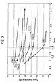
- Fig. 7 shows its characteristic diagram, where Case 1 to Case 7 are set to have respective dynamic spring constants K1, horizontally transverse distances L1 and L2 from the gravity center G of the unit as given below.
- Case 6 and Case 7 are of a liquid-sealed vibration-proof mount, P designating a peak frequency of loss factor.
- the coefficient C is set to be in a range of 1.3 or more and more preferably less than 1.9, taking the influence upon sound vibration performance of the vehicle in the case of too large coefficient C values into account.
- the peak frequency PHz of loss factor Lf in the vertical direction of the one mount RH of a liquid-sealed type as defined above, it is possible to set the peak frequency in a frequency band deviated significantly from the natural frequency value (7.9 Hz) of the drive unit in the vertical direction, for example 12 to 17 Hz, preferably in the vicinity of 15 Hz, as a result of which the vertical vibrations are suppressed owing to antiresonance of the unit and the vertical vibrations of the floor affecting largely the riding comfort, particularly those in a frequency band of 12 to 17 Hz can be reduced.
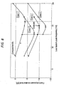
- Fig. 8 shows a change in improved level of vibrations of the floor with the variation in peak frequency of loss factor.
- a liquid-sealed mount RH and a non-hydraulic mount LH are used and arranged as illustrated in Figs. 1 and 2 and the transverse distances L1 and L2 from the gravity center G are 500 mm and 400 mm
- the frequency response analysis on the vertical vibrations of the floor was conducted with the present example and comparative example when dynamic spring constants and loss factors Lf at 10 Hz in the vertical, lateral and fore-and-aft (front-to-rear) directions were set as given in Table 1 below. The results obtained are shown in Fig. 5.
- the example of the invention meets equation (a) as regards the dynamic spring constants K1 and K2 in the vertical direction of both mounts and simultaneously satisfies equation (b) as regards the peak frequency PHz of loss factor Lf in the vertical direction of the one liquid-enclosed type mount RH.
- equation (b) as regards the peak frequency PHz of loss factor Lf in the vertical direction of the one liquid-enclosed type mount RH.
- this liquid-sealed mount RH is indicated in solid lines for the dynamic spring constant and frequency characteristic of the loss factor.
- the comparative example does not meet equations (a) and (b) above.
- the dash lines indicate the dynamic spring constant and the frequency characteristic of loss factor of the liquid-enclosed mount RH in the comparative example, wherein the peak frequency PHz of loss factor Lf is nearly equal to the natural frequency value (7.9 Hz) of the drive unit in the Vertical direction.
- Kd 10 designates a dynamic spring constant at a frequency of 10 Hz, "Lf 10", a loss factor at 10 Hz, and “Lf/Hz” of the right-hand mount RH in the vertical direction, a peak loss factor value and its frequency.
- the vertical vibrations of the floor in the comparative example are, as shown in dash lines, appreciably large in the vicinity of 12 Hz ⁇ 15 Hz whereas those of the example of this invention are, as shown in solid lines, significantly reduced especially in the frequency band of 12 to 17 Hz, so that the riding comfort performance is improved.
- Fig. 8 indicates a change in improvement level of the vibrations of the floor due to the variation in peak frequency of the loss factor of the one liquid-sealed type mount RH.
- Case 1 to Case 4 are set to have respective values of the dynamic spring constant K1, the horizontally transverse distances L1, L2 from the gravity center G of the unit as mentioned below.
- Case 1 corresponds to the comparative example in Table 1 above and does not satisfy equation (a).
- Case 2 to Case 4 are concerned with examples of this invention, among which Case 3 corresponds to the example of the invention in Table 1 above.
- the right-hand mount RH in the running direction of the vehicle was of a liquid-sealed type and the other left-hand mount LH was of a non-liquid-sealed type.
- a liquid-sealed type of mount is arranged on the left-hand in the running direction of the vehicle whereas a non-liquid-sealed type mount is arranged on the other side, or construct both of a liquid-sealed type, depending upon the installation conditions of the drive unit.
- both mounts of a non-liquid-sealed type may be used.
- the vertical vibrations of the floor at a frequency in the vicinity of 15 Hz can be significantly suppressed and consequently, it is possible to improve the riding comfort performance of an automotive vehicle equipped with it.
Landscapes
- Engineering & Computer Science (AREA)
- General Engineering & Computer Science (AREA)
- Mechanical Engineering (AREA)
- Chemical & Material Sciences (AREA)
- Combustion & Propulsion (AREA)
- Transportation (AREA)
- Arrangement Or Mounting Of Propulsion Units For Vehicles (AREA)
- Combined Devices Of Dampers And Springs (AREA)
- Springs (AREA)
- Body Structure For Vehicles (AREA)
Applications Claiming Priority (1)
| Application Number | Priority Date | Filing Date | Title |
|---|---|---|---|
| PCT/JP2001/005866 WO2003004297A1 (fr) | 2001-07-05 | 2001-07-05 | Structure de support d'une unite de dispositif de disque |
Publications (3)
| Publication Number | Publication Date |
|---|---|
| EP1410937A1 true EP1410937A1 (fr) | 2004-04-21 |
| EP1410937A4 EP1410937A4 (fr) | 2009-06-24 |
| EP1410937B1 EP1410937B1 (fr) | 2013-06-05 |
Family
ID=11737521
Family Applications (1)
| Application Number | Title | Priority Date | Filing Date |
|---|---|---|---|
| EP01947870.0A Expired - Lifetime EP1410937B1 (fr) | 2001-07-05 | 2001-07-05 | Structure de support d'une unite de dispositif de disque |
Country Status (4)
| Country | Link |
|---|---|
| US (1) | US20040026838A1 (fr) |
| EP (1) | EP1410937B1 (fr) |
| JP (1) | JP3718749B2 (fr) |
| WO (1) | WO2003004297A1 (fr) |
Cited By (1)
| Publication number | Priority date | Publication date | Assignee | Title |
|---|---|---|---|---|
| EP1908618A1 (fr) * | 2006-10-03 | 2008-04-09 | Clark Equipment Company | Suspension de moteur |
Families Citing this family (5)
| Publication number | Priority date | Publication date | Assignee | Title |
|---|---|---|---|---|
| FR2877414B1 (fr) * | 2004-10-28 | 2007-04-27 | Hutchinson Sa | Procede d'equilibrage pour moteur et dispositif pour la mise en oeuvre de ce procede |
| JP4715190B2 (ja) * | 2004-12-20 | 2011-07-06 | 日産自動車株式会社 | 車両のエンジン搭載構造 |
| JP2007331645A (ja) * | 2006-06-16 | 2007-12-27 | Daihatsu Motor Co Ltd | 車両の駆動ユニット支持構造 |
| JP4695033B2 (ja) * | 2006-07-21 | 2011-06-08 | 本田技研工業株式会社 | 車両用パワーユニット支持装置 |
| JP6334254B2 (ja) * | 2014-05-15 | 2018-05-30 | 株式会社ブリヂストン | エンジン装置支持構造、及び、エンジン装置設置方法 |
Family Cites Families (12)
| Publication number | Priority date | Publication date | Assignee | Title |
|---|---|---|---|---|
| US3825090A (en) * | 1973-08-08 | 1974-07-23 | Gen Motors Corp | Rotary engine and transmission assembly mounting system |
| JPS5940946A (ja) | 1982-09-01 | 1984-03-06 | Nissan Motor Co Ltd | 車両用パワ−ユニツトの支持構造 |
| JPH0775943B2 (ja) * | 1985-03-26 | 1995-08-16 | ヤマハ発動機株式会社 | 車両のエンジン懸架構造 |
| JP2617715B2 (ja) * | 1987-04-17 | 1997-06-04 | 株式会社ブリヂストン | 防振装置の減衰係数制御装置 |
| FR2633223B1 (fr) * | 1988-06-22 | 1990-10-12 | Peugeot | Structure avant de vehicule automobile a moteur transversal |
| JP2510168Y2 (ja) * | 1990-05-17 | 1996-09-11 | 三菱自動車工業株式会社 | 慣性主軸式エンジンマウント構造 |
| US5452575A (en) * | 1993-09-07 | 1995-09-26 | General Electric Company | Aircraft gas turbine engine thrust mount |
| DE19628181A1 (de) * | 1996-07-12 | 1998-01-15 | Porsche Ag | Lagerung für eine Brennkraftmaschine |
| JP3052853B2 (ja) * | 1996-10-04 | 2000-06-19 | トヨタ自動車株式会社 | パワーユニットの懸架装置 |
| JP3341638B2 (ja) * | 1997-07-11 | 2002-11-05 | トヨタ自動車株式会社 | パワートレーンの懸架装置 |
| US6871820B2 (en) * | 1999-06-30 | 2005-03-29 | Mark Conrad Wilksch | Aircraft engine mounting |
| US6435487B1 (en) * | 1999-07-12 | 2002-08-20 | Toyo Tire & Rubber Co., Ltd. | Liquid sealed type vibration isolator |
-
2001
- 2001-07-05 US US10/168,711 patent/US20040026838A1/en not_active Abandoned
- 2001-07-05 WO PCT/JP2001/005866 patent/WO2003004297A1/fr not_active Ceased
- 2001-07-05 JP JP2002553786A patent/JP3718749B2/ja not_active Expired - Fee Related
- 2001-07-05 EP EP01947870.0A patent/EP1410937B1/fr not_active Expired - Lifetime
Cited By (1)
| Publication number | Priority date | Publication date | Assignee | Title |
|---|---|---|---|---|
| EP1908618A1 (fr) * | 2006-10-03 | 2008-04-09 | Clark Equipment Company | Suspension de moteur |
Also Published As
| Publication number | Publication date |
|---|---|
| EP1410937A4 (fr) | 2009-06-24 |
| EP1410937B1 (fr) | 2013-06-05 |
| JPWO2003004297A1 (ja) | 2004-10-21 |
| JP3718749B2 (ja) | 2005-11-24 |
| WO2003004297A1 (fr) | 2003-01-16 |
| US20040026838A1 (en) | 2004-02-12 |
Similar Documents
| Publication | Publication Date | Title |
|---|---|---|
| US4203499A (en) | Apparatus for preventing or damping vibrations and noise in a vehicle | |
| US4420060A (en) | Engine mount arrangement | |
| EP0224355A2 (fr) | Unité de montage pour un corps oscillant | |
| US4456213A (en) | Engine mounting structure | |
| JPS5943657B2 (ja) | 自動車用エンジンマウント | |
| US4779853A (en) | Method of determining and damping vibrations | |
| JP2715699B2 (ja) | ストラットサスペンションの上部取付構造 | |
| JP2599196Y2 (ja) | 車両のエンジンマウント | |
| EP1410937A1 (fr) | Structure de support d'une unite de dispositif de disque | |
| EP0040327A2 (fr) | Structure de montage pour moteur de véhicule automobile | |
| GB2102534A (en) | Fluid-filled engine mount device | |
| JPS629041A (ja) | 防振ゴム装置 | |
| KR20210129421A (ko) | 자동차용 병렬형 엔진마운트 | |
| JPH0874922A (ja) | 可動弁式流体封入防振支持装置 | |
| EP1262682A1 (fr) | Antivibrateur a liquide | |
| JPS63111241A (ja) | エンジン・トランスミツシヨン系のカバ−構造 | |
| EP0521987B1 (fr) | Moyen d'attenuation de vibrations | |
| JPS6216345B2 (fr) | ||
| JPH0516629A (ja) | ブツシユ | |
| US20030030199A1 (en) | Liquid-filled type vibration isolator | |
| JPH0362935B2 (fr) | ||
| JPH06193670A (ja) | 流体封入式防振装置 | |
| JPS5845135Y2 (ja) | エンジン支持装置 | |
| JPH09273586A (ja) | 防振装置 | |
| JP3072407B2 (ja) | 円筒型液封入防振マウント |
Legal Events
| Date | Code | Title | Description |
|---|---|---|---|
| PUAI | Public reference made under article 153(3) epc to a published international application that has entered the european phase |
Free format text: ORIGINAL CODE: 0009012 |
|
| 17P | Request for examination filed |
Effective date: 20040130 |
|
| AK | Designated contracting states |
Kind code of ref document: A1 Designated state(s): DE FR GB |
|
| A4 | Supplementary search report drawn up and despatched |
Effective date: 20090528 |
|
| 17Q | First examination report despatched |
Effective date: 20091221 |
|
| REG | Reference to a national code |
Ref country code: DE Ref legal event code: R079 Ref document number: 60148055 Country of ref document: DE Free format text: PREVIOUS MAIN CLASS: B60K0017120000 Ipc: B60K0005120000 |
|
| RIC1 | Information provided on ipc code assigned before grant |
Ipc: B60K 5/12 20060101AFI20110922BHEP Ipc: F16F 7/10 20060101ALI20110922BHEP Ipc: F16F 13/10 20060101ALI20110922BHEP |
|
| GRAP | Despatch of communication of intention to grant a patent |
Free format text: ORIGINAL CODE: EPIDOSNIGR1 |
|
| GRAS | Grant fee paid |
Free format text: ORIGINAL CODE: EPIDOSNIGR3 |
|
| GRAA | (expected) grant |
Free format text: ORIGINAL CODE: 0009210 |
|
| AK | Designated contracting states |
Kind code of ref document: B1 Designated state(s): DE FR GB |
|
| REG | Reference to a national code |
Ref country code: GB Ref legal event code: FG4D |
|
| REG | Reference to a national code |
Ref country code: DE Ref legal event code: R096 Ref document number: 60148055 Country of ref document: DE Effective date: 20130801 |
|
| PLBE | No opposition filed within time limit |
Free format text: ORIGINAL CODE: 0009261 |
|
| STAA | Information on the status of an ep patent application or granted ep patent |
Free format text: STATUS: NO OPPOSITION FILED WITHIN TIME LIMIT |
|
| 26N | No opposition filed |
Effective date: 20140306 |
|
| REG | Reference to a national code |
Ref country code: DE Ref legal event code: R097 Ref document number: 60148055 Country of ref document: DE Effective date: 20140306 |
|
| REG | Reference to a national code |
Ref country code: FR Ref legal event code: PLFP Year of fee payment: 15 |
|
| PGFP | Annual fee paid to national office [announced via postgrant information from national office to epo] |
Ref country code: GB Payment date: 20150701 Year of fee payment: 15 Ref country code: DE Payment date: 20150630 Year of fee payment: 15 |
|
| PGFP | Annual fee paid to national office [announced via postgrant information from national office to epo] |
Ref country code: FR Payment date: 20150629 Year of fee payment: 15 |
|
| REG | Reference to a national code |
Ref country code: DE Ref legal event code: R119 Ref document number: 60148055 Country of ref document: DE |
|
| GBPC | Gb: european patent ceased through non-payment of renewal fee |
Effective date: 20160705 |
|
| PG25 | Lapsed in a contracting state [announced via postgrant information from national office to epo] |
Ref country code: FR Free format text: LAPSE BECAUSE OF NON-PAYMENT OF DUE FEES Effective date: 20160801 Ref country code: DE Free format text: LAPSE BECAUSE OF NON-PAYMENT OF DUE FEES Effective date: 20170201 |
|
| REG | Reference to a national code |
Ref country code: FR Ref legal event code: ST Effective date: 20170331 |
|
| PG25 | Lapsed in a contracting state [announced via postgrant information from national office to epo] |
Ref country code: GB Free format text: LAPSE BECAUSE OF NON-PAYMENT OF DUE FEES Effective date: 20160705 |