EP1414615B1 - Carter d'entrainement destine a des entrainements de machines-outils - Google Patents
Carter d'entrainement destine a des entrainements de machines-outils Download PDFInfo
- Publication number
- EP1414615B1 EP1414615B1 EP02794584A EP02794584A EP1414615B1 EP 1414615 B1 EP1414615 B1 EP 1414615B1 EP 02794584 A EP02794584 A EP 02794584A EP 02794584 A EP02794584 A EP 02794584A EP 1414615 B1 EP1414615 B1 EP 1414615B1
- Authority
- EP
- European Patent Office
- Prior art keywords
- drive housing
- segments
- stacking direction
- cutouts
- cooling channel
- Prior art date
- Legal status (The legal status is an assumption and is not a legal conclusion. Google has not performed a legal analysis and makes no representation as to the accuracy of the status listed.)
- Expired - Lifetime
Links
- 239000000463 material Substances 0.000 claims abstract description 95
- 238000001816 cooling Methods 0.000 claims description 82
- 239000002826 coolant Substances 0.000 claims description 16
- 238000004519 manufacturing process Methods 0.000 claims description 9
- 229910000679 solder Inorganic materials 0.000 claims description 6
- 230000006698 induction Effects 0.000 claims description 4
- 238000013461 design Methods 0.000 claims description 2
- 239000000109 continuous material Substances 0.000 claims 1
- 239000013589 supplement Substances 0.000 claims 1
- 230000001502 supplementing effect Effects 0.000 claims 1
- 238000005266 casting Methods 0.000 description 12
- 230000002349 favourable effect Effects 0.000 description 11
- 238000000034 method Methods 0.000 description 10
- 229910000831 Steel Inorganic materials 0.000 description 5
- 238000005516 engineering process Methods 0.000 description 5
- 239000000314 lubricant Substances 0.000 description 5
- 239000010959 steel Substances 0.000 description 5
- 238000003860 storage Methods 0.000 description 5
- 238000012546 transfer Methods 0.000 description 4
- 230000015572 biosynthetic process Effects 0.000 description 3
- 238000005219 brazing Methods 0.000 description 3
- 230000001427 coherent effect Effects 0.000 description 3
- 238000005520 cutting process Methods 0.000 description 3
- 238000003698 laser cutting Methods 0.000 description 3
- 238000003754 machining Methods 0.000 description 3
- 230000017525 heat dissipation Effects 0.000 description 2
- 238000010438 heat treatment Methods 0.000 description 2
- 238000005461 lubrication Methods 0.000 description 2
- 238000005476 soldering Methods 0.000 description 2
- 238000012549 training Methods 0.000 description 2
- 229910000760 Hardened steel Inorganic materials 0.000 description 1
- 230000001154 acute effect Effects 0.000 description 1
- 238000004026 adhesive bonding Methods 0.000 description 1
- 238000004873 anchoring Methods 0.000 description 1
- 230000000295 complement effect Effects 0.000 description 1
- 230000001627 detrimental effect Effects 0.000 description 1
- 238000009792 diffusion process Methods 0.000 description 1
- 238000006073 displacement reaction Methods 0.000 description 1
- 238000003780 insertion Methods 0.000 description 1
- 230000037431 insertion Effects 0.000 description 1
- 238000002955 isolation Methods 0.000 description 1
- 239000002184 metal Substances 0.000 description 1
- 238000005457 optimization Methods 0.000 description 1
- 238000002360 preparation method Methods 0.000 description 1
- 238000005096 rolling process Methods 0.000 description 1
- 230000006641 stabilisation Effects 0.000 description 1
- 238000011105 stabilization Methods 0.000 description 1
- 239000002699 waste material Substances 0.000 description 1
Images




Classifications
-
- B—PERFORMING OPERATIONS; TRANSPORTING
- B23—MACHINE TOOLS; METAL-WORKING NOT OTHERWISE PROVIDED FOR
- B23B—TURNING; BORING
- B23B9/00—Automatic or semi-automatic turning-machines with a plurality of working-spindles, e.g. automatic multiple-spindle machines with spindles arranged in a drum carrier able to be moved into predetermined positions; Equipment therefor
- B23B9/005—Spindle carriers: constructional details, drives for the spindles, or the like
-
- B—PERFORMING OPERATIONS; TRANSPORTING
- B23—MACHINE TOOLS; METAL-WORKING NOT OTHERWISE PROVIDED FOR
- B23P—METAL-WORKING NOT OTHERWISE PROVIDED FOR; COMBINED OPERATIONS; UNIVERSAL MACHINE TOOLS
- B23P15/00—Making specific metal objects by operations not covered by a single other subclass or a group in this subclass
-
- B—PERFORMING OPERATIONS; TRANSPORTING
- B23—MACHINE TOOLS; METAL-WORKING NOT OTHERWISE PROVIDED FOR
- B23Q—DETAILS, COMPONENTS, OR ACCESSORIES FOR MACHINE TOOLS, e.g. ARRANGEMENTS FOR COPYING OR CONTROLLING; MACHINE TOOLS IN GENERAL CHARACTERISED BY THE CONSTRUCTION OF PARTICULAR DETAILS OR COMPONENTS; COMBINATIONS OR ASSOCIATIONS OF METAL-WORKING MACHINES, NOT DIRECTED TO A PARTICULAR RESULT
- B23Q1/00—Members which are comprised in the general build-up of a form of machine, particularly relatively large fixed members
- B23Q1/01—Frames, beds, pillars or like members; Arrangement of ways
- B23Q1/015—Frames, beds, pillars
-
- B—PERFORMING OPERATIONS; TRANSPORTING
- B23—MACHINE TOOLS; METAL-WORKING NOT OTHERWISE PROVIDED FOR
- B23Q—DETAILS, COMPONENTS, OR ACCESSORIES FOR MACHINE TOOLS, e.g. ARRANGEMENTS FOR COPYING OR CONTROLLING; MACHINE TOOLS IN GENERAL CHARACTERISED BY THE CONSTRUCTION OF PARTICULAR DETAILS OR COMPONENTS; COMBINATIONS OR ASSOCIATIONS OF METAL-WORKING MACHINES, NOT DIRECTED TO A PARTICULAR RESULT
- B23Q1/00—Members which are comprised in the general build-up of a form of machine, particularly relatively large fixed members
- B23Q1/70—Stationary or movable members for carrying working-spindles for attachment of tools or work
-
- B—PERFORMING OPERATIONS; TRANSPORTING
- B23—MACHINE TOOLS; METAL-WORKING NOT OTHERWISE PROVIDED FOR
- B23Q—DETAILS, COMPONENTS, OR ACCESSORIES FOR MACHINE TOOLS, e.g. ARRANGEMENTS FOR COPYING OR CONTROLLING; MACHINE TOOLS IN GENERAL CHARACTERISED BY THE CONSTRUCTION OF PARTICULAR DETAILS OR COMPONENTS; COMBINATIONS OR ASSOCIATIONS OF METAL-WORKING MACHINES, NOT DIRECTED TO A PARTICULAR RESULT
- B23Q11/00—Accessories fitted to machine tools for keeping tools or parts of the machine in good working condition or for cooling work; Safety devices specially combined with or arranged in, or specially adapted for use in connection with, machine tools
- B23Q11/12—Arrangements for cooling or lubricating parts of the machine
- B23Q11/126—Arrangements for cooling or lubricating parts of the machine for cooling only
- B23Q11/127—Arrangements for cooling or lubricating parts of the machine for cooling only for cooling motors or spindles
-
- B—PERFORMING OPERATIONS; TRANSPORTING
- B23—MACHINE TOOLS; METAL-WORKING NOT OTHERWISE PROVIDED FOR
- B23P—METAL-WORKING NOT OTHERWISE PROVIDED FOR; COMBINED OPERATIONS; UNIVERSAL MACHINE TOOLS
- B23P2700/00—Indexing scheme relating to the articles being treated, e.g. manufactured, repaired, assembled, connected or other operations covered in the subgroups
- B23P2700/12—Laminated parts
-
- Y—GENERAL TAGGING OF NEW TECHNOLOGICAL DEVELOPMENTS; GENERAL TAGGING OF CROSS-SECTIONAL TECHNOLOGIES SPANNING OVER SEVERAL SECTIONS OF THE IPC; TECHNICAL SUBJECTS COVERED BY FORMER USPC CROSS-REFERENCE ART COLLECTIONS [XRACs] AND DIGESTS
- Y10—TECHNICAL SUBJECTS COVERED BY FORMER USPC
- Y10T—TECHNICAL SUBJECTS COVERED BY FORMER US CLASSIFICATION
- Y10T82/00—Turning
- Y10T82/20—Lathe for screw cutting
-
- Y—GENERAL TAGGING OF NEW TECHNOLOGICAL DEVELOPMENTS; GENERAL TAGGING OF CROSS-SECTIONAL TECHNOLOGIES SPANNING OVER SEVERAL SECTIONS OF THE IPC; TECHNICAL SUBJECTS COVERED BY FORMER USPC CROSS-REFERENCE ART COLLECTIONS [XRACs] AND DIGESTS
- Y10—TECHNICAL SUBJECTS COVERED BY FORMER USPC
- Y10T—TECHNICAL SUBJECTS COVERED BY FORMER US CLASSIFICATION
- Y10T82/00—Turning
- Y10T82/25—Lathe
- Y10T82/2552—Headstock
-
- Y—GENERAL TAGGING OF NEW TECHNOLOGICAL DEVELOPMENTS; GENERAL TAGGING OF CROSS-SECTIONAL TECHNOLOGIES SPANNING OVER SEVERAL SECTIONS OF THE IPC; TECHNICAL SUBJECTS COVERED BY FORMER USPC CROSS-REFERENCE ART COLLECTIONS [XRACs] AND DIGESTS
- Y10—TECHNICAL SUBJECTS COVERED BY FORMER USPC
- Y10T—TECHNICAL SUBJECTS COVERED BY FORMER US CLASSIFICATION
- Y10T82/00—Turning
- Y10T82/25—Lathe
- Y10T82/2552—Headstock
- Y10T82/2562—Spindle and bearings
Definitions
- the invention relates to a drive housing for machine tool drives.
- Castings produced Drive housings for machine tool drives are commonly referred to as Castings produced.
- a housing which comprises a plurality of stacked in a stacking direction, cut out of flat material and extending in stacking planes transverse to the stacking segments segments each of which has interconnected web systems, which extend in the stacking direction successive segments abut each other with their material web systems with the formation of overlapping surfaces and in the region of their overlapping surfaces are connected flat and cohesively with each other.
- the invention is based on the object, a drive housing for To create machine tool drives, which opens the possibility with simple production technology with regard to the recesses to be provided no restrictions.
- the manufacturing technology for the drive housing is independent of the Complexity of the material web systems and thus the resulting recesses in the drive housing.
- the only constraint is the material web systems have overlapping surfaces with one another must, in the area of which a flat cohesive connection between the individual segments is feasible.
- a flat cohesive connection is in several ways, for example can be realized by gluing.
- a particularly advantageous solution provides that the two-dimensional cohesive Connection takes place through a solder layer.
- solder layer has the advantage that the individual segments as Stack stack to a preform of the drive housing, with between The segments capillary gaps are made, in which then the heating Draws in solder layer due to capillary action.
- solder material can be preferably in the region of the overlapping surfaces a full-surface cohesive connection in the region of the overlapping surface between the segments.
- the cutouts can have any shape.
- the material web systems at least partially enclose the cutouts.
- the solution according to the invention provides that receiving cutouts are provided in the segments, a in the stacking direction within the drive housing across the segments extending recess for receiving a machine tool element form.
- Such a machine tool element may be mentioned at the outset Machine tool drive or any kind of in a machine tool usable part, such as a supply line or supply line be for the machine tool drive.
- Another type of machine tool element may be parts of a drive train or parts of a displacement drive, such as a Be sled drive the machine tool.
- part of the Segments has the receiving cutouts surrounding wall webs, which with material in the stacking direction preceding and subsequent material webs have associated overlap areas and a recess enclosing wall with improved in the area of the wall webs Form heat conduction.
- the wall webs are formed so that they are a recess form of a cooling medium separating wall, so that the cooling medium Contact directly the wall bars and the heat from the wall bars can dissipate.
- the wall webs are formed so that they are in the stack levels have a width, along the same by less than a factor two varies in order to ensure a uniform heat conduction through the wall webs to be able to realize.
- the wall webs at least over a partial circumference of Extending receiving cut and thus as far as possible a perimeter of the Allow receiving section to take place heat dissipation.
- a particularly favorable design of the wall webs provides that this one the receiving cutout facing away from outer contour, whose course the one of the receiving cut facing inner contour of the wall webs essentially follows, that is, that the width of the wall webs in the stack levels between the inner and outer contour is approximately constant.
- the thickness of the segments in principle is freely selectable, sees a structurally particularly favorable constructed embodiment a drive housing before that a segment with a wall web between two segments with a support bar, so that for stability reasons to be represented width of a wall web between two support webs possibly be realized by a single segment.
- the sum of the overlap surfaces interconnected Materialstegsysteme a spatially coherent, self-supporting structure for the machine tool drive form, so that the machine tool drive itself stable in the Drive housing can be stored.
- the solution according to the invention also offers particular advantages in terms of the acquisition of the machine tool drive acting on the drive housing forces, since the material web systems be adapted to these forces at each location of the drive housing can.
- the material web systems thereby form a kind of spatial Tensile structure system, in which both in the stacking direction and transversely to the stacking direction intermediate spaces between the individual structural elements are feasible.
- the drive housing is designed so that the supporting structure Material webs has, compared to other material webs in the stack levels widened executed and arranged extending in Hauptlastraumen are.
- An advantageous embodiment provides that the forming the structure Material webs are designed as material web rings.
- the receiving cutout at least one the segments a bearing seat for a bearing of the machine tool drive forms. This means that through the receiving cut of at least one of the segments or of several segments directly a bearing seat for the Bearings of a machine tool drive can be formed, so that directly by the production of the cutouts already produced the bearing seat is and thus at least rough machining operations, which in castings are common, can be omitted.
- the bearing seat through the receiving cutouts several segments is formed and at least one part forms segments of these segments, which allow the best possible heat flow.
- already described wall webs can thus also optimally dissipate the heat generated in the area of the bearing seat, wherein these wall webs preferably formed in the same way and also between support webs are arranged, in turn, in the region of the bearing seat to create the required stability.
- Such position-defining elements can, for example, any type of Be anchoring flanges.
- a position-locking element is but also, for example, a sprocket, which allows any rotational positions set and set the drive housing.
- the solution according to the invention offers In general, the great advantage that also the material strengths of the individual Segments of the drive housing in each case to the respective load requirements let adjust. For example, in the area of a position-defining Element or in the area of a bearing seat or in the area of Wings a material with higher strength for the production of the segments used, as in the areas of the drive housing, in which the surface loads, in particular the surface loads, are lower.
- cooling channel cutouts of in Stacking direction successive segments form cooling duct sections, which run with deflections through the drive housing. Such deflections improve the thermal contact between the through this Cooling duct sections guided cooling medium.
- a particularly favorable realization form provides that the cooling passage section approximately in the direction transverse to the stack axis.
- the segments are stacked in the stacking direction and preferably in the Stacking direction the cutouts are provided with overlap, can be at the solution according to the invention also a course of the cooling channel section across to the stacking direction.
- cooling channel section can be a particularly favorable heat dissipation then realize when the Cooling channel section in the direction of the stacking direction forming meander and between the cooling channel cutouts of at least two segments replaced.
- a structurally particularly feasible embodiment provides that the cooling channel portion partially in a segment transverse to the stacking direction runs and in the stacking direction by the material web systems of the preceding and the next segment.
- cooling channel section can be a particularly expedient Meandering form then constructively simple form, if the Cooling passage section in the course of its extension transverse to the stack axis of one segment into the next segment and then back into the one Segment changes.
- Cooling channel cutouts which differs in a stacking direction Complete cooling duct section.
- cooling channel cutouts in the Segments to a stacking direction, but transverse to the stacking direction at least one meander having cooling duct section complement, so that even in these cooling duct sections a particularly favorable Heat transfer to the cooling medium can be realized.
- a particularly favorable form provides that the cooling duct section a in has the stacked planes curved shape, so that the cooling channel section for example, can be adapted to a cutout forming a bearing seat and thus at least in a part of the cooling passage section as possible uniform heat transfer from the bearing seat to that in the cooling passage section guided cooling medium takes place.
- the cooling passage section in particularly favorable Consider the stability as the wall between the cooling duct section and the bearing seat in a simple manner to the stability requirements can be adapted.
- cooling passage section itself Has meandering transverse to the stacking meander, in which case in this Case preferably the meanders in curved in the stacking levels form.
- Such a material selection would be the entire material web system of the relevant segment.
- the web systems are made of a hardenable material.
- the Material web systems before assembly of the drive housing partially to harden and then manufacture the drive housing as a whole.
- This solution is also particularly advantageous in that thus the cohesive Connecting the segments together, for example by brazing, no negative, and in particular no depending on the segments has different negative influence on the hardness, since the hardening of all the desired area tangent material web systems different Segments after the material connection of the same takes place.
- the material web systems When hardening the material of the material web systems are very different Provisions conceivable. For example, it would be conceivable, the material web systems harden by diffusion hardening or laser hardening.
- a particularly advantageous procedure provides that the material through Induction hardening is curable.
- the drive housing has a guide surface formed by at least one segment for a movable machine element.
- a movable machine element Under such a movable machine element are the most diverse To understand parts.
- a movable Machine element a rotating shaft or a linearly moving Guide body, for example a carriage for workpieces or tools, be.
- the guide surface can extend both transversely to the stacking direction. However, it is within the scope of the inventive solution also conceivable that the guide surface extends in the stacking direction over a plurality of segments. In this case, the guide surface is preferably by Nachberin the Drive housing in the range of these segments in the required surface quality produced.
- guide surfaces usually limited surfaces of the drive housing are, it is preferably provided that the guide surface by a surface a portion of the material web system of the respective segment is formed.
- the surface may be in the region of an inner contour of the respective segment lie, but it is also conceivable that the surface in the area of Outside contour of the respective segment is located.
- guide surfaces are these through the surface of a narrow side or several narrow sides formed several web systems in a subarea thereof.
- the subregion of the material web system is cured, which, however, assumes that the material web system in this case made of a hardenable material.
- the guide surface is formed by a hardened surface.
- the guide surface can basically a guide surface for each type be on this supporting machine elements. For example could such a machine element by rolling on this guide surface support.
- the Guide surface is a sliding guide surface.
- FIG. 1 first embodiment of a whole with 10th designated drive housing for a designated as a whole by 12
- Machine tool drive represents a spindle drum, in which as Machine tool drives a plurality of motor spindles is arranged.
- the spindle drum 10 as a whole is in a part of a machine frame forming stand 14 rotatable about a spindle drum axis 16, However, stored in the individual rotational positions fixable.
- the storage of the spindle drum 16 in the stator 14 is done partially by outer wings 18, on corresponding wings 20 of the Stand 14 abut.
- the spindle housing 10 is the drive housing performing an outer sprocket 22, in which a drawing not shown Pinion meshes, to rotational movements about the spindle drum axis 16th drivable.
- the trained as a spindle motor 12 work spindle 12 is in turn by a front spindle bearing 24, located at a first bearing seat 26 of the spindle drum 10 is supported and supported by a rear spindle bearing 28, which via a retaining ring 30 at a second bearing seat 32 of the spindle drum supported about a spindle axis 34 rotatably in the spindle drum 10th stored.
- a spindle drum Drive housing 10 formed from a plurality of segments 40a to 40z, all made of flat material, such as steel plates, cut out and in an in this case parallel to the spindle drum axis 16 extending stacking direction 42 stacked on each other and cohesively, for example by Soldering by means of a brazing process, in the area of overlapping surfaces 44 between adjacent, adjacent segments 40 with each other are connected, wherein the cohesive connection of the segments 40th Overlapping surfaces 44 Kapillarspalte form, in which the solder material at Heating flows in and over these over the entire overlap areas 44 distributed.
- the individual segments 40 are plane-parallel to each other Surfaces provided and extend in perpendicular to Stacking direction 42 extending stacking levels 46, wherein the thickness in the Stacking direction 42 can vary freely.
- the segments 40e to 40h formed by 50 and 52 designated as material web systems are provided with a plurality of cutouts 54, 56, 58 and 60, which over the entire thickness of the web systems 50 and 52 through the extend respective segment 40 therethrough, and preferably by laser cutting the flat material, in particular the flat steel are made.
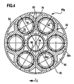
- Fig. 2 for example, form as receiving cutouts serving cutouts 54c to 54z in total one parallel to the stacking direction 42 extending recess 70 for receiving a machine tool element, in this case, the work spindle 12, wherein the recess 70 extends through the entire drive housing 10 therethrough.
- the recess 70 is in the area between the segment 40e to 40h surrounded by a cooled wall 72, which alternately through each other Wall webs 74, shown using the example of the segment 40f and Support webs 76, shown on the example of the segment 40g, is formed.
- a stator 73 is located directly on the cooled wall 72 and is thus able to heat the waste directly into the cooled wall 72 to initiate.
- the wall webs 74 extend to a substantial extent to the Recess 70 around and have in the stack levels 46 a width, which is significantly smaller than a width of the support webs 76, which is also in the essentially closed around the recess 70 extend around.
- the wall webs 70 separate in the serving as a cooling channel cutouts Cutouts 58 existing cooling medium from the recess 70, wherein the Wall webs 74 are formed so that they have a good heat conduction between one for forming an inner, the machine tool drive 12 facing Wall surface contributing inner contour 78 and a cooling medium facing outer contour 80 to efficiently remove the heat from the Inner surface of the cooled wall 72 can dissipate.
- the support webs 76 in the stacking levels 46 have a greater width and also extend between in the same segment 40g adjacent cooling channel cutouts 54 so that they around each cutout 54 form around a support ring 82, which between an outer, the outer contour 62 of the segment 40g forming outer ring 84 and one Support rings 82 inside the drive housing supporting inner ring 86th lie, which encloses the cutout 56.
- the cutouts 54 enclose Support rings 82, the outer ring 84 and the inner ring 86, the material web system 52 of the same.
- the material web system 50 of the segment 40f on the one hand the wall webs 74 already described, which formed the receiving cutouts 54 substantially enclose and in a to the outer contour 62nd contributing outer ring 88 pass over and in an interior of the Segments 40f are interconnected via intermediate webs 90.
- the material web system 50 of the segment 40f contributes only to a small extent Stability of the drive housing 10 in the direction transverse to the stacking direction, while the overwhelming contributions to this stability are made by the material web system 52 of the segment 40g are delivered.
- each web system 50 connects two on both sides thereof arranged web systems 52, so that the total material web systems 50 and 52 of all segments 40, for example segments 40e until 40h, forms a spatially coherent self-supporting structure, that in the stacking direction 42 due to the superimposed segments 40th anyway has a great stability and by alternating between the Segments 40f with the material web systems 50 arranged segments 40g with material web systems 52 also across the stacking direction 42 a large Stability.
- the respective recesses 70 for receiving form the machine tool drives 12 form the cutouts 56th the segments 40 a recess 92, which is also in the stacking direction extends through the entire drive housing 10 and, as in Fig. 1st shown, for receiving machine elements 94, for example leads to the machine tool drives 12 is used.
- the recess 92 with the respective recesses 70 connected via a side channel 96 which in the region of the segments 40l to 40p is formed by suitably shaped cutouts 98 and preferably obliquely, in particular at an acute angle to the stacking direction 42 from the recess 92 extends into the respective recess 70.
- the recess 92 serves for the discharge a cooling medium.
- the segments 40g and 40f provided with the designed as a cooling channel cutouts 58 are arranged so that the cutouts 58A, 58C and 58E in the segment 40f partially overlap with the cutouts 58B and 58D in the segment 40g and Overall, a meandering transverse to the stacking direction 42 Form cooling passage portion 104, as shown in detail in Fig. 5 fragmentary shown.
- the cooling medium for example cooling air
- the cooling medium for example cooling air
- the recess 92 has both the function of a recording and a cooling passage section.
- a cooling passage portion indicated as a whole by 104 which is provided with its main direction is transverse to the stacking direction 42 and thereby in the stacking direction two meanders 100 and 102 forms and extend from the outer contour 62 of the drive housing 10 extends to the recess 92 out.
- this cooling channel section 104 takes place an efficient cooling, in particular the wall webs 74 and thus due to their small width in the stacking levels 46 efficient cooling the wall 72 in total, the sections formed by the wall webs 74 becomes.
- the cooling channel sections 104 do not run in isolation from each other, but instead due to the fact that on a segment 40g turn the one Segment 40f follows this segment is in the area of congruent mutually facing cutouts 58B and 58D and the respective Overlapping these cutouts 58B and 58D with the cutouts 58A, 58C and 58E also in the stacking direction 52 a connection between the individual Cooling channel segments 104, thus a total of a coherent cooling channel system 106 form, on the one hand the cooling duct sections 104 and additionally also the recess 92 as a central channel comprises.
- cutouts 60 in the individual segments formed in all segments 40e to 40h are preferably congruent, also a channel 110, however, for example, as a cavity for perennialserspamis serves.
- the drive housing 10 is also still in the range of Bearing seat 26, for example, between the segments 40s and 40z second cooling channel system 120, which, as shown in FIGS. 6 to 8, for example, has a cutout 122 in a segment 40u, For example, it only extends through the segment 40u and with overlaps a cutout 124 in the segment 40t, which extends in the azimuthal direction 126 extends around the bearing seat 26, wherein between the cutout 124th and the bearing seat 26 in turn a wall web 130 remains, which in the direction the stacking levels 46 has a small width to a possible good heat transfer between an inner contour 132 of the wall web and an outer contour 134 of the wall web limiting the cutout 124 to reach.
- cooling channel system 120 is the possibility of a in Stacking direction 42 extending cooling channel portion 118, formed by the To realize cutouts 122 and 124 of successive segments 40, which has in a curved surface 136 meander 138, the run transversely to the stacking direction 42.
- the segments 40 serve not only to recesses 70 and 90 for Inclusion of machine tool drives 12 or machine elements or cooling duct systems 106 or 120 in a drive housing 10, but may also serve to support the wings 18 for storage the drive housing 10 to form, for example, the wings 18th is formed by the outer contour 62 of the segments 40l to 40p.
- a segment 40d in such a way that that its outer contour has the shape of the ring gear 22, the to serves to drive the entire drive housing 10 in rotation in the stator 14, so that the ring gear 22 is not in this case, as in conventional Technology is placed as a separate part on the drive housing 10, but is an integral part of the segment 40d.
- FIG. 9 An illustrated in Fig. 9 embodiment of a designated as a whole by 10 ' Drive housing for a machine tool drive designated as a whole by 12 ', in this case a drive for a carriage 140, is held on a machine frame 142.
- the drive housing 10 ' is also made of a Variety of segments 40'a to 40'z formed, all made of flat material, for example Steel plates, cut out and in the stacking direction 42 to each other stacked and cohesively, for example by soldering by means of a Brazing process in the area of overlapping areas 44 between adjacent Segments, interconnected, as already detailed is described in connection with the first embodiment.
- the individual segments 40 extend with each other plane-parallel Surfaces also parallel to perpendicular to the stacking direction 42 extending Stacking levels 46, wherein as in the first embodiment, the Thickness of the segments in the stack direction 42 may vary freely.
- segment 40f includes a web system 150f, which has a plurality of cutouts 154, 156A and 156B and 162A, 162B and 162C.
- the web system 150f has, in the same way as in the first Embodiment described, total contiguous material webs on.
- the cutouts 162A to 162C form one to one essential part in the stacking plane 46f through the drive housing 10 'extending Lubricant channel which an inlet 165 supplied Lubricant around the cutouts 156B and 154 around outlet openings 166A and 166B in drive housing 10 '.
- cutouts 162A, 162B and 162C are not interconnected, to ensure that the material web system 150 of the segment 40'f remains connected.
- the material web system 150f is designed to be continuous, are each between facing ends 163A and 163B of the cutouts 162A and 162B web portions 164 are provided and between facing ends 163C and 163D of the cutouts 162B and 162C also web portions 164, each of the ends 163A and 163B and separate 163C and 163D.
- FIG Fig. 12 in addition to the cutouts 154 and 156A and 156B cutouts 162D and 162E provided with the ends 163A and 163B as well 163C and 163D of the cutouts 162A and 162B and 162B and 162C overlapping, respectively are arranged and thus connections between these cutouts to prevent lubricant flow from the cutout 162A in FIG the cutouts 162B and from the cutouts 162B into the cutouts 162C permit.
- the cutouts 162D and 162E thus serve the material web areas 164 and 164 between the facing ends 163A and 163B and 163C and 163D of the cutouts 162A and 162B and 162B and 162C, respectively.
- the cutouts 162 are for Lubricant is no longer available, but it is a cutout 158A provided which alsgabelt starting from a cooling air inlet 157 to ends 159A, which faces ends 159B of the cutouts 158B with the cutouts 158B on opposite sides of the cutout 154j are lying.
- the cutout 158'A formed enlarged again, with its fork-shaped sections are extend with their ends 159'A so far that they are connected to the ends 159B of the Segments 40'j and 40'k overlap, so that the cutout 158'A in the segment 40'l the ends 159A and 159B between the cutouts 158A and 158B in Segment 40'j bypassed.
- cutouts 158C are provided, which are connected to the ends 159B opposite ends 159C of the cutouts 158B are arranged overlapping are.
- segment 40'p in FIG. 15 they extend starting from the ends 159'A of the section 158'A of the segments 40'I to 40'n formed by in the subsequent segments and each overlapping arranged cutouts 158D and arranged by the overlapping Cutouts 158C, which are also present in segment 40'p, Feed channels 168 in the stacking direction 42 along the drive housing 10 ', and up to a segment 40'y, shown in Fig.16, in which the cutouts 158'D and 158'C are enclosed in a cutout 154y Recess 70 open, which also in the stacking direction 42 substantially through the entire drive housing 10 'extends.
- cooling air inlet 157 supplied cooling air is thus on the cutouts 158A and 158'A and the cutouts 158B on all four channels 168 distributed and along the drive housing 10 'in the stacking direction 42 to the segment 40'y guided and there over the cutouts 158'D and 158'C in the recess 70 delivered.
- a stator 173 is corresponding to the segment 40'p by a segment packet Segments held in which the section 154p to the in Stacking direction 42 extending motor axis 34 'formed around toothed and has projections 155, between which recesses 153 are located. there protuberances 155 carry the stator 173, while in the recesses 153 the cooling air in the stacking direction 42 along the stator 173 in the direction of the segment 40'o can flow, in which then the cutout 154b so shaped is that an outlet opening 176 is formed, through which then exit the cooling air can.
- the cooling air can also still on the overlapping cutouts 156A and 156B forming channels 178A and 178B respectively, the bearing seat 26 'for the Bearing 24 'of the machine tool drive 10' cooling flow around and on a stacking direction 42 the cooling air inlet 157 opposite side emerge from the drive housing 10 '.
- These guide surfaces 180a and 180b serve the purpose of the machine tool drive 12 'movable carriage 140 to guide exactly, wherein the guiding action of the guide surfaces 180a and 180b as in FIG. 11 exemplified, is still supplemented by this opposite and facing guide surfaces 182A and 182B, and lateral guide surfaces 184A and 184B formed on guide rails 186A and 186B with these guide rails 186A and 186B with the drive housing 10 'are connected.
- the guide surfaces 180A and 180B are sliding surfaces for this facing Sliding surfaces 188A and 188B of the carriage 140 and therefore must inevitably be created and hardened surfaces.
- the web systems 150 of all segments 40 ' are off a hardenable material, preferably a hardenable steel, which expediently after production of the drive housing 10 ' from the segments 40 'harden.
- a preferred hardening process is in induction hardening, which it for example allowed to the manufactured to guide surfaces 180A, 180B adjacent areas 190A and 190B targeted hardening.
- induction hardening would be, for example, other selective ones Hardening process.
- the sub-segments 40'f to 40'I which with their cutout 154F to 154I the bearing seat 26 'for the bearing 24' of the machine tool drive 12 ' form, also in a subsequent to the section 154 and in to harden the web system 150 in the inwardly extending region 200 to achieve a higher stability in the region of the bearing seat 26 '.
- the lubricant supply can be supplied via the Cutouts 162 are used to lubricate the guide of the carriage 140 be on the one hand, a lubrication in the area of the guide surfaces 180th takes place and on the other hand, a lubrication in the of the guide rails 186th provided guide surfaces 182 and 184.
Landscapes
- Engineering & Computer Science (AREA)
- Mechanical Engineering (AREA)
- Machine Tool Units (AREA)
- Surgical Instruments (AREA)
Abstract
Claims (40)
- Carter comprenant une multiplicité de segments (40) empilés dans une direction d'empilement (42), découpés dans un matériau plat et s'étendant dans des plans d'empilement (46) de façon transversale par rapport à la direction d'empilement (42), segments dont chacun présente des systèmes continus d'âmes de matériaux (50, 52, 150) qui s'étendent de manière telle, que des segments (40), qui se suivent dans la direction d'empilement (42), soient contigus entre eux, par leurs systèmes d'âmes des matériaux (50, 52, 150), en formant des surfaces de chevauchement (44) et, dans la zone de leurs surfaces de chevauchement (44), sont reliés en nappes les uns aux autres et par continuité de matière, caractérisé en ce que, pour la configuration du carter comme carter d'entraínement pour des machines-outils, il est prévu, dans les segments (40), des découpes de logements (54, 56, 154) qui forment un évidement (70, 92, 70') s'étendant dans la direction d'empilement (42), à l'intérieur du carter d'entraínement (10), en dépassant des segments (40), cet évidement servant au logement d'un élément (12, 94) de la machine-outil, et en ce qu'une partie des segments (40) présente des âmes de paroi (74) entourant les découpes de logements (54), lesquelles âmes de paroi présentent des zones de chevauchement (44) reliées par continuité de matière, dans la direction d'empilement (42), à des âmes de matériaux (52) précédentes et suivantes et forment une paroi (72) entourant l'évidement (70), cette paroi ayant une meilleure conduction de chaleur dans la zone des âmes de paroi (74).
- Carter d'entraínement selon la revendication 1, caractérisé en ce que les segments (40) sont reliés l'un à l'autre, par continuité de matière, par une couche de brasage en nappe.
- Carter d'entraínement selon la revendication 1 ou 2, caractérisé en ce que, s'agissant d'au moins une partie des segments (40), les systèmes d'âmes de matériaux (50, 52) présentent des découpes (54, 56, 58, 60, 122, 124, 154, 156, 158, 162) traversant les segments (40) sur toute leur épaisseur.
- Carter d'entraínement selon l'une quelconque des revendications précédentes, caractérisé en ce que les systèmes d'âmes de matériaux (50, 52, 150) entourent au moins partiellement les découpes (54, 56, 58, 60, 122, 124, 154, 156, 158, 162).
- Carter d'entraínement selon l'une quelconque des revendications précédentes, caractérisé en ce que l'évidement (70, 92, 70') formé par les découpes de logements (54, 56, 154) s'étend à travers la totalité du carter d'entraínement (10).
- Carter d'entraínement selon l'une quelconque des revendications précédentes, caractérisé en ce que les âmes de paroi (74) forment une paroi (72) séparant l'évidement (70), d'un milieu de refroidissement.
- Carter d'entraínement selon l'une quelconque des revendications précédentes, caractérisé en ce que les âmes de paroi (74) présentent, dans les plans d'empilement (46), une largeur qui varie, le long de ces âmes de paroi, de moins d'un facteur deux.
- Carter d'entraínement selon l'une quelconque des revendications précédentes, caractérisé en ce que les âmes de paroi (74) s'étendent au moins sur une circonférence partielle de la découpe de logement (54).
- Carter d'entraínement selon l'une quelconque des revendications précédentes, caractérisé en ce que les âmes de paroi (74) présentent un contour extérieur (80) placé à l'opposé de la découpe de logement (54), contour extérieur dont le profil suit pratiquement un contour intérieur (78) tourné vers la découpe de logement (54).
- Carter d'entraínement selon l'une quelconque des revendications précédentes, caractérisé en ce que, dans la direction d'empilement (42), des deux côtés d'un segment (40f) ayant une âme de paroi (74), suivent des segments (40g) ayant des âmes porteuses (76) qui sont configurées, dans les plans d'empilement (46), en étant plus larges que les âmes de paroi (74).
- Carter d'entraínement selon la revendication 10, caractérisé en ce qu'un segment (40f) ayant une âme de paroi (74) se situe entre deux segments (40g) ayant une âme porteuse (76).
- Carter d'entraínement selon l'une quelconque des revendications précédentes, caractérisé en ce que la somme des systèmes d'âmes de matériaux (50, 52, 150) reliés en nappes les uns aux autres, dans les surfaces de chevauchement (44), forme une structure autoporteuse continue dans l'espace, pour l'entraínement (12) des machines-outils.
- Carter d'entraínement selon la revendication 12, caractérisé en ce que le carter d'entraínement présente des âmes de matériaux (82, 84, 86) formant la structure, lesquelles âmes de matériaux sont configurées en étant élargies par rapport à d'autres âmes de matériaux (74, 90) situées dans les plans d'empilement (46) et sont disposées en passant dans des directions de charges principales.
- Carter d'entraínement selon l'une quelconque des revendications précédentes, caractérisé en ce que la découpe de logement (54, 154) d'au moins l'un des segments (40s ... 40z, 40'f ... 40'n) forme un siège de roulement (26, 26') pour un roulement (24, 24') de l'entraínement (12, 12') des machines-outils.
- Carter d'entraínement selon la revendication 14, caractérisé en ce que le siège de roulement (26) est formé par les découpes de logements (54) de plusieurs segments (40a, 40v), et au moins une partie de ces segments (40u, 40v) forme des âmes de paroi (120) ayant un meilleur flux de chaleur.
- Carter d'entraínement selon l'une quelconque des revendications précédentes, caractérisé en ce qu'au moins l'un des segments (40e ... 40f) forme, par son contour extérieur (16), une surface portante (18) pour le carter d'entraínement (10).
- Carter d'entraínement selon l'une quelconque des revendications précédentes, caractérisé en ce qu'au moins l'un des segments (40d) forme un élément (22) fixant une position du carter d'entraínement (10).
- Carter d'entraínement selon l'une quelconque des revendications précédentes, caractérisé en ce qu'au moins une partie des segments (40g, 40f) présente des découpes de conduits de refroidissement (56, 58, 112, 114, 156, 158) qui forment au moins une partie de conduit de refroidissement (104, 118, 168) d'un système de conduits de refroidissement (106, 120) s'étendant à travers le carter d'entraínement (10).
- Carter d'entraínement selon la revendication 18, caractérisé en ce que les découpes de conduits de refroidissement (58, 112, 114) de segments (40) qui se suivent dans la direction d'empilement (42) forment des parties de conduits de refroidissement (104, 118) qui, en comportant des coudes (100, 102, 128), s'étendent à travers le carter d'entraínement (10).
- Carter d'entraínement selon la revendication 18 ou 19, caractérisé en ce que les parties de conduits de refroidissement (104, 111) comportant de multiples coudes (100, 102, 128) s'étendent à travers le carter d'entraínement (10).
- Carter d'entraínement selon l'une quelconque des revendications 18 à 20, caractérisé en ce que la partie de conduit de refroidissement (104) s'étend à peu près dans une direction orientée de façon transversale par rapport à la direction d'empilement (42).
- Carter d'entraínement selon la revendication 21, caractérisé en ce que la partie de conduit de refroidissement (104) présente des méandres se formant dans le sens de la direction d'empilement (42) et change entre les découpes de conduits de refroidissement (58) d'au moins deux segments (40g, 40f).
- Carter d'entraínement selon la revendication 21 ou 22, caractérisé en ce que la partie de conduit de refroidissement (104) s'étend, par zones, dans un segment (40f) disposé de façon transversale par rapport à la direction d'empilement (42) et, dans la direction d'empilement (42), est obturée par les systèmes d'âmes de matériaux (50, 52, 150) du segment précédent et du segment suivant (40g).
- Carter d'entraínement selon l'une quelconque des revendications 21 à 23, caractérisé en ce que la partie de conduit de refroidissement (104), au cours de son étendue se formant transversalement par rapport à la direction d'empilement (42) d'au moins un segment (40f), change dans le segment suivant (40g) et ensuite, au retour, dans l'un des segments (40f).
- Carter d'entraínement selon l'une quelconque des revendications 18 à 24, caractérisé en ce qu'une partie des segments (40u, 40v) présente des découpes de conduits de refroidissement (122, 124, 158) qui s'ajoutent à une partie de conduit de refroidissement (118, 168) s'étendant dans la direction d'empilement (42).
- Carter d'entraínement selon la revendication 25, caractérisé en ce que les parties de conduits de refroidissement (122, 124) s'ajoutent, dans les segments (40u, 40v), à une partie de conduit de refroidissement (118) s'étendant dans la direction d'empilement (42) mais de façon transversale par rapport à la direction d'empilement (42) et présentant au moins un méandre (138).
- Carter d'entraínement selon la revendication 26, caractérisé en ce que la partie de conduit de refroidissement (118) présente une forme courbe dans les plans d'empilement (46).
- Carter d'entraínement selon la revendication 26 ou 27, caractérisé en ce que la partie de conduit de refroidissement (118) présente des méandres (138) se formant de façon transversale par rapport à la direction d'empilement (42).
- Carter d'entraínement selon l'une quelconque des revendications précédentes, caractérisé en ce qu'au moins dans le cas d'une partie des segments (40'), les systèmes d'âmes de matériaux (150) sont fabriqués dans un matériau durcissable.
- Carter d'entraínement selon la revendication 29, caractérisé en ce que les systèmes d'âmes de matériaux (150) sont fabriqués dans un matériau durcissable après fabrication du carter d'entraínement (10').
- Carter d'entraínement selon la revendication 30, caractérisé en ce que le matériau est durcissable par trempe par induction.
- Carter d'entraínement selon l'une quelconque des revendications précédentes, caractérisé en ce que le carter d'entraínement (10') présente une surface de guidage (180) formée par au moins un segment (40') et prévue pour un élément de machine mobile (140).
- Carter d'entraínement selon la revendication 32, caractérisé en ce que la surface de guidage (180) s'étend, dans la direction d'empilement (42), sur plusieurs segments (40').
- Carter d'entraínement selon la revendication 32 ou 33, caractérisé en ce que la surface de guidage (180) est formée par une surface d'une zone partielle (190) du système d'âmes de matériaux (150) du segment respectif (40').
- Carter d'entraínement selon l'une quelconque des revendications 32 à 34, caractérisé en ce que la surface (180) se situe dans la zone d'un contour extérieur du segment respectif (40').
- Carter d'entraínement selon l'une quelconque des revendications 32 à 35, caractérisé en ce que la surface de guidage (180) est formée par la surface d'un petit côté dans une zone partielle (190) du système d'âmes de matériaux respectif (150).
- Carter d'entraínement selon la revendication 36, caractérisé en ce que la zone partielle (190) du système d'âmes de matériaux (150) est trempée.
- Carter d'entraínement selon l'une quelconque des revendications 32 à 37, caractérisé en ce que la surface de guidage (180) est une surface trempée.
- Carter d'entraínement selon la revendication 38, caractérisé en ce que la surface de guidage (180) présente une courbe de dureté pratiquement constante dans la direction d'empilement (42).
- Carter d'entraínement selon l'une quelconque des revendications 32 à 39, caractérisé en ce que la surface de guidage (180) est une surface de guidage à glissement.
Applications Claiming Priority (3)
| Application Number | Priority Date | Filing Date | Title |
|---|---|---|---|
| DE10140253 | 2001-08-09 | ||
| DE10140253A DE10140253A1 (de) | 2001-08-09 | 2001-08-09 | Antriebsgehäuse für Werkzeugmaschinenantriebe |
| PCT/EP2002/008902 WO2003013781A1 (fr) | 2001-08-09 | 2002-08-09 | Carter d'entrainement destine a des entrainements de machines-outils |
Publications (2)
| Publication Number | Publication Date |
|---|---|
| EP1414615A1 EP1414615A1 (fr) | 2004-05-06 |
| EP1414615B1 true EP1414615B1 (fr) | 2005-07-06 |
Family
ID=7695666
Family Applications (1)
| Application Number | Title | Priority Date | Filing Date |
|---|---|---|---|
| EP02794584A Expired - Lifetime EP1414615B1 (fr) | 2001-08-09 | 2002-08-09 | Carter d'entrainement destine a des entrainements de machines-outils |
Country Status (6)
| Country | Link |
|---|---|
| US (1) | US7021183B2 (fr) |
| EP (1) | EP1414615B1 (fr) |
| JP (1) | JP2004537430A (fr) |
| DE (2) | DE10140253A1 (fr) |
| ES (1) | ES2244830T3 (fr) |
| WO (1) | WO2003013781A1 (fr) |
Cited By (2)
| Publication number | Priority date | Publication date | Assignee | Title |
|---|---|---|---|---|
| DE102010002804A1 (de) * | 2010-03-12 | 2011-09-15 | Index-Werke Gmbh & Co. Kg Hahn & Tessky | Mehrspindeldrehmaschine |
| CN103143729A (zh) * | 2013-04-03 | 2013-06-12 | 云南Cy集团有限公司 | 一种高性价比的重载型数控卧式车床 |
Families Citing this family (2)
| Publication number | Priority date | Publication date | Assignee | Title |
|---|---|---|---|---|
| CN110340383B (zh) * | 2019-05-23 | 2021-02-02 | 广州市昊志机电股份有限公司 | 一种自动换刀的高精度气浮电主轴 |
| DE102019124524A1 (de) | 2019-09-12 | 2021-03-18 | Index-Werke Gmbh & Co. Kg Hahn & Tessky | Werkzeugmaschine |
Family Cites Families (14)
| Publication number | Priority date | Publication date | Assignee | Title |
|---|---|---|---|---|
| US3999445A (en) * | 1975-07-07 | 1976-12-28 | Liautaud James P | Pinion gear |
| DE3026685A1 (de) * | 1980-07-15 | 1982-02-11 | Rudolf Prof.Dr.-Ing. 5100 Aachen Koller | Zahnrad |
| US4422498A (en) * | 1981-09-08 | 1983-12-27 | Yci Usa, Inc. | Machine tool cooling system |
| US4630498A (en) * | 1982-07-30 | 1986-12-23 | Briggs & Stratton Corp. | Laminated wheel assembly |
| US4795012A (en) * | 1987-05-26 | 1989-01-03 | Borg-Warner Automotive, Inc. | Spiral spring disc torsional coupling |
| DE4040554A1 (de) * | 1990-12-18 | 1992-07-02 | Maho Ag | Werkzeugmaschine zur abtragenden werkstueckbearbeitung mittels laserstrahls |
| FR2707339B1 (fr) * | 1993-07-08 | 1996-10-31 | Volkswagen Ag | Came, en particulier pour commander une soupape de changement de charge. |
| GB2289742B (en) * | 1994-05-27 | 1998-12-09 | Western Atlas Uk Ltd | Drive transmitting device |
| JPH0946938A (ja) * | 1995-07-26 | 1997-02-14 | Toshiba Corp | スピンドルモータ及びその製造方法、並びにスピンドルモータを備えた磁気ディスク装置 |
| US5657679A (en) * | 1995-12-26 | 1997-08-19 | Multi-Products, Inc. | Method and apparatus for separating an LOM sculpture from an adherent base |
| US5730817A (en) * | 1996-04-22 | 1998-03-24 | Helisys, Inc. | Laminated object manufacturing system |
| DE19958146A1 (de) * | 1999-12-03 | 2001-06-07 | Volkswagen Ag | Verfahren zur Herstellung von dreidimensionalen Körpern |
| DE10001523C1 (de) * | 2000-01-15 | 2001-06-28 | Ralf Joerg Redlin | Verfahren zur Herstellung von Bauelementen in Compound-Bauweise |
| DE10010028A1 (de) * | 2000-03-02 | 2001-09-06 | Volkswagen Ag | Stator für eine elektrische Maschine |
-
2001
- 2001-08-09 DE DE10140253A patent/DE10140253A1/de not_active Ceased
-
2002
- 2002-08-09 DE DE50203584T patent/DE50203584D1/de not_active Expired - Lifetime
- 2002-08-09 WO PCT/EP2002/008902 patent/WO2003013781A1/fr not_active Ceased
- 2002-08-09 JP JP2003518770A patent/JP2004537430A/ja active Pending
- 2002-08-09 ES ES02794584T patent/ES2244830T3/es not_active Expired - Lifetime
- 2002-08-09 EP EP02794584A patent/EP1414615B1/fr not_active Expired - Lifetime
-
2004
- 2004-02-06 US US10/773,936 patent/US7021183B2/en not_active Expired - Lifetime
Cited By (3)
| Publication number | Priority date | Publication date | Assignee | Title |
|---|---|---|---|---|
| DE102010002804A1 (de) * | 2010-03-12 | 2011-09-15 | Index-Werke Gmbh & Co. Kg Hahn & Tessky | Mehrspindeldrehmaschine |
| US8844412B2 (en) | 2010-03-12 | 2014-09-30 | Index-Werke Gmbh & Co. Kg Hahn & Tessky | Multispindle lathe |
| CN103143729A (zh) * | 2013-04-03 | 2013-06-12 | 云南Cy集团有限公司 | 一种高性价比的重载型数控卧式车床 |
Also Published As
| Publication number | Publication date |
|---|---|
| JP2004537430A (ja) | 2004-12-16 |
| ES2244830T3 (es) | 2005-12-16 |
| EP1414615A1 (fr) | 2004-05-06 |
| WO2003013781A1 (fr) | 2003-02-20 |
| DE10140253A1 (de) | 2003-03-06 |
| US20040154444A1 (en) | 2004-08-12 |
| US7021183B2 (en) | 2006-04-04 |
| DE50203584D1 (de) | 2005-08-11 |
Similar Documents
| Publication | Publication Date | Title |
|---|---|---|
| DE69819821T2 (de) | Werkzeugmaschine | |
| DE69502550T2 (de) | Profilanpassung für Vielwalzengerüste | |
| EP0854987B1 (fr) | Boíte de vitesses et palier pour la même | |
| EP0361027B1 (fr) | Fraise à profiler | |
| EP2792442B1 (fr) | Outil d'écroutage pour l'écroutage d'une denture sur une pièce à couronne dentée | |
| DE2438442C2 (de) | Schlitzwerkzeug in einer Vorrichtung zur Herstellung von geschlitzten und gegebenenfalls gestreckten Blechen | |
| EP2681000A1 (fr) | Filière | |
| DE2639890B2 (de) | Scheibenfräser | |
| EP3838463A1 (fr) | Procédé de finition d'une pièce pourvue d'une denture | |
| DE3346462A1 (de) | Verfahren zur herstellung einer zahnstange, insbesondere fuer ein lenkgetriebe mit einem variablen uebersetzungsverhaeltnis | |
| DE69310991T2 (de) | Strangpressmatrize und mit ihr durchgeführtes Strangpressverfahren | |
| DE202005002831U1 (de) | Ausgangskomponente für Sägeblätter bzw. Sägebänder | |
| DE4402843A1 (de) | Räumvorrichtung | |
| EP1414615B1 (fr) | Carter d'entrainement destine a des entrainements de machines-outils | |
| EP2171313B1 (fr) | Gamme de transmissions et procédé de production de transmissions | |
| CH683449A5 (de) | Lagerblock zur Halterung mehrerer Lager. | |
| EP2329944A2 (fr) | Presse destinée à produire une force de pression pour le traitement d'une pièce | |
| DE69705221T2 (de) | Metallplattenbiegevorrichtung mit offsetdruckrollen | |
| DE3924884C3 (de) | Werkzeug zum spanabhebenden Bearbeiten von Werkstücken | |
| DE69631272T2 (de) | Verfahren und Vorrichtung zur Herstellung von Draht | |
| EP1238752A1 (fr) | Machine outil | |
| DE69015532T2 (de) | Schneidapparat. | |
| EP1644151B1 (fr) | Dispositif pour l'usinage et/ou la formation d'un évidement dans une pièce | |
| DE3621422C2 (fr) | ||
| DE560568C (de) | Verfahren zum genauen Fertigbearbeiten roh vorgearbeiteter Zahnraeder |
Legal Events
| Date | Code | Title | Description |
|---|---|---|---|
| PUAI | Public reference made under article 153(3) epc to a published international application that has entered the european phase |
Free format text: ORIGINAL CODE: 0009012 |
|
| 17P | Request for examination filed |
Effective date: 20040218 |
|
| AK | Designated contracting states |
Kind code of ref document: A1 Designated state(s): AT BE BG CH CY CZ DE DK EE ES FI FR GB GR IE IT LI LU MC NL PT SE SK TR |
|
| 17Q | First examination report despatched |
Effective date: 20040806 |
|
| GRAP | Despatch of communication of intention to grant a patent |
Free format text: ORIGINAL CODE: EPIDOSNIGR1 |
|
| RBV | Designated contracting states (corrected) |
Designated state(s): CH CZ DE ES IT LI |
|
| GRAS | Grant fee paid |
Free format text: ORIGINAL CODE: EPIDOSNIGR3 |
|
| GRAA | (expected) grant |
Free format text: ORIGINAL CODE: 0009210 |
|
| AK | Designated contracting states |
Kind code of ref document: B1 Designated state(s): CH CZ DE ES IT LI |
|
| REG | Reference to a national code |
Ref country code: CH Ref legal event code: EP |
|
| REF | Corresponds to: |
Ref document number: 50203584 Country of ref document: DE Date of ref document: 20050811 Kind code of ref document: P |
|
| REG | Reference to a national code |
Ref country code: CH Ref legal event code: NV Representative=s name: KIRKER & CIE SA |
|
| REG | Reference to a national code |
Ref country code: ES Ref legal event code: FG2A Ref document number: 2244830 Country of ref document: ES Kind code of ref document: T3 |
|
| PLBE | No opposition filed within time limit |
Free format text: ORIGINAL CODE: 0009261 |
|
| STAA | Information on the status of an ep patent application or granted ep patent |
Free format text: STATUS: NO OPPOSITION FILED WITHIN TIME LIMIT |
|
| 26N | No opposition filed |
Effective date: 20060407 |
|
| PGFP | Annual fee paid to national office [announced via postgrant information from national office to epo] |
Ref country code: CH Payment date: 20071106 Year of fee payment: 6 |
|
| PGFP | Annual fee paid to national office [announced via postgrant information from national office to epo] |
Ref country code: CZ Payment date: 20080625 Year of fee payment: 7 |
|
| PGFP | Annual fee paid to national office [announced via postgrant information from national office to epo] |
Ref country code: ES Payment date: 20080804 Year of fee payment: 7 |
|
| REG | Reference to a national code |
Ref country code: CH Ref legal event code: PL |
|
| PG25 | Lapsed in a contracting state [announced via postgrant information from national office to epo] |
Ref country code: CH Free format text: LAPSE BECAUSE OF NON-PAYMENT OF DUE FEES Effective date: 20080831 Ref country code: LI Free format text: LAPSE BECAUSE OF NON-PAYMENT OF DUE FEES Effective date: 20080831 |
|
| PG25 | Lapsed in a contracting state [announced via postgrant information from national office to epo] |
Ref country code: CZ Free format text: LAPSE BECAUSE OF NON-PAYMENT OF DUE FEES Effective date: 20090809 |
|
| REG | Reference to a national code |
Ref country code: ES Ref legal event code: FD2A Effective date: 20090810 |
|
| PG25 | Lapsed in a contracting state [announced via postgrant information from national office to epo] |
Ref country code: ES Free format text: LAPSE BECAUSE OF NON-PAYMENT OF DUE FEES Effective date: 20090810 |
|
| REG | Reference to a national code |
Ref country code: DE Ref legal event code: R082 Ref document number: 50203584 Country of ref document: DE Representative=s name: HOEGER, STELLRECHT & PARTNER PATENTANWAELTE MB, DE |
|
| REG | Reference to a national code |
Ref country code: DE Ref legal event code: R082 Ref document number: 50203584 Country of ref document: DE Representative=s name: HOEGER, STELLRECHT & PARTNER PATENTANWAELTE MB, DE |
|
| PGFP | Annual fee paid to national office [announced via postgrant information from national office to epo] |
Ref country code: IT Payment date: 20210826 Year of fee payment: 20 |
|
| PGFP | Annual fee paid to national office [announced via postgrant information from national office to epo] |
Ref country code: DE Payment date: 20210830 Year of fee payment: 20 |
|
| REG | Reference to a national code |
Ref country code: DE Ref legal event code: R071 Ref document number: 50203584 Country of ref document: DE |