EP1416233A2 - Adsorptions-Kühlapparat mit Pufferspeicher - Google Patents
Adsorptions-Kühlapparat mit Pufferspeicher Download PDFInfo
- Publication number
- EP1416233A2 EP1416233A2 EP03017429A EP03017429A EP1416233A2 EP 1416233 A2 EP1416233 A2 EP 1416233A2 EP 03017429 A EP03017429 A EP 03017429A EP 03017429 A EP03017429 A EP 03017429A EP 1416233 A2 EP1416233 A2 EP 1416233A2
- Authority
- EP
- European Patent Office
- Prior art keywords
- adsorption
- heat
- evaporator
- phase
- during
- Prior art date
- Legal status (The legal status is an assumption and is not a legal conclusion. Google has not performed a legal analysis and makes no representation as to the accuracy of the status listed.)
- Granted
Links
Images

Classifications
-
- F—MECHANICAL ENGINEERING; LIGHTING; HEATING; WEAPONS; BLASTING
- F25—REFRIGERATION OR COOLING; COMBINED HEATING AND REFRIGERATION SYSTEMS; HEAT PUMP SYSTEMS; MANUFACTURE OR STORAGE OF ICE; LIQUEFACTION SOLIDIFICATION OF GASES
- F25B—REFRIGERATION MACHINES, PLANTS OR SYSTEMS; COMBINED HEATING AND REFRIGERATION SYSTEMS; HEAT PUMP SYSTEMS
- F25B17/00—Sorption machines, plants or systems, operating intermittently, e.g. absorption or adsorption type
- F25B17/08—Sorption machines, plants or systems, operating intermittently, e.g. absorption or adsorption type the absorbent or adsorbent being a solid, e.g. salt
-
- F—MECHANICAL ENGINEERING; LIGHTING; HEATING; WEAPONS; BLASTING
- F25—REFRIGERATION OR COOLING; COMBINED HEATING AND REFRIGERATION SYSTEMS; HEAT PUMP SYSTEMS; MANUFACTURE OR STORAGE OF ICE; LIQUEFACTION SOLIDIFICATION OF GASES
- F25D—REFRIGERATORS; COLD ROOMS; ICE-BOXES; COOLING OR FREEZING APPARATUS NOT OTHERWISE PROVIDED FOR
- F25D11/00—Self-contained movable devices, e.g. domestic refrigerators
-
- F—MECHANICAL ENGINEERING; LIGHTING; HEATING; WEAPONS; BLASTING
- F25—REFRIGERATION OR COOLING; COMBINED HEATING AND REFRIGERATION SYSTEMS; HEAT PUMP SYSTEMS; MANUFACTURE OR STORAGE OF ICE; LIQUEFACTION SOLIDIFICATION OF GASES
- F25B—REFRIGERATION MACHINES, PLANTS OR SYSTEMS; COMBINED HEATING AND REFRIGERATION SYSTEMS; HEAT PUMP SYSTEMS
- F25B2339/00—Details of evaporators; Details of condensers
- F25B2339/04—Details of condensers
- F25B2339/046—Condensers with refrigerant heat exchange tubes positioned inside or around a vessel containing water or pcm to cool the refrigerant gas
-
- F—MECHANICAL ENGINEERING; LIGHTING; HEATING; WEAPONS; BLASTING
- F25—REFRIGERATION OR COOLING; COMBINED HEATING AND REFRIGERATION SYSTEMS; HEAT PUMP SYSTEMS; MANUFACTURE OR STORAGE OF ICE; LIQUEFACTION SOLIDIFICATION OF GASES
- F25D—REFRIGERATORS; COLD ROOMS; ICE-BOXES; COOLING OR FREEZING APPARATUS NOT OTHERWISE PROVIDED FOR
- F25D23/00—General constructional features
- F25D23/003—General constructional features for cooling refrigerating machinery
-
- F—MECHANICAL ENGINEERING; LIGHTING; HEATING; WEAPONS; BLASTING
- F25—REFRIGERATION OR COOLING; COMBINED HEATING AND REFRIGERATION SYSTEMS; HEAT PUMP SYSTEMS; MANUFACTURE OR STORAGE OF ICE; LIQUEFACTION SOLIDIFICATION OF GASES
- F25D—REFRIGERATORS; COLD ROOMS; ICE-BOXES; COOLING OR FREEZING APPARATUS NOT OTHERWISE PROVIDED FOR
- F25D2700/00—Means for sensing or measuring; Sensors therefor
- F25D2700/12—Sensors measuring the inside temperature
Definitions
- the invention relates to a periodically operating adsorption refrigerator with buffer memory and a method for its operation according to the preamble of Claim 1.
- Adsorption refrigerators are devices in which a solid sorbent is present vaporous working fluid with heat release at medium temperature level sorbed (adsorption phase).
- the working fluid evaporates in an evaporator with heat absorption at a lower temperature level. After the adsorption phase the working fluid can be heated at a high temperature be desorbed again (desorption phase).
- Working equipment evaporates the sorbent and flows into a condenser. There is the work equipment liquefied back and then evaporated again in the evaporator.
- Adsorption cooling apparatus with solid sorbents are from EP 0 368 111 and DE-OS 34 25 419 known.
- Sorbent container filled with sorbent suck working steam, which is generated in an evaporator, and sorb it in the sorbent filling, releasing heat.
- the Sorption heat must be removed from the sorbent filling.
- the Chillers can be used to cool and keep food warm in thermal insulated containers are used. Between the evaporator and the sorbent these cooling devices contain a shut-off device. This allows one Evaporation and sorption of the working fluid at a later point in time.
- the adsorption cooling apparatus known from EP 0 368 111 consists of a transportable cooling unit and a separable, stationary charging station.
- the cooling unit contains a sorption container filled with a solid sorbent and an evaporator with liquid working fluid.
- evaporators and sorption containers together via a lockable steam line connected.
- Liquid heat flows through a heat exchanger embedded in the evaporator Media caused by temperature-controlled opening and closing of the shut-off device be cooled to the desired temperature level. After that Sorbent is saturated with working fluid, it can be heated in the charging station become.
- the working fluid vapor flowing out is reliquefied in the evaporator.
- the heat of condensation is due to cooling water that is embedded by the Heat exchanger flows, discharged.
- shut-off devices serve on the one hand during the desorption phase uncouple the evaporator from the rest of the refrigerator to allow it to flow in to prevent hot working steam in the cold evaporator and on the other hand, during the adsorption phase the refrigeration in the evaporator to regulate or postpone it to a later date. Without shut-off device will always be the evaporator during the desorption phase hot and therefore the medium to be cooled which is in contact with it is warm.
- the object of the present invention is in an adsorption refrigerator without shut-off device according to the preamble of claim 1 that to be cooled Protect medium in the desorption phase against inadmissible heating.
- the coupling of the condenser to a buffer storage allows a significantly faster desorption and, consequently, a higher desorption performance, since the heat of condensation can be dissipated more effectively, for example due to the onset of convection.
- the desorption phase can thus be significantly shortened compared to the adsorption phase.
- the medium to be cooled is less exposed to the high liquefaction temperatures.
- the desorption phase can be reduced to a few minutes, while the adsorption phase can last from several hours to several days. During this long adsorption phase, the buffer storage can slowly dissipate the heat load consumed at high power and via small heat exchanger surfaces.
- the evaporator is particularly advantageous in relation to what is to be cooled Medium is arranged so that it is relatively little during the desorption phase Emits heat. This is achieved e.g. in that there is relatively little to cool Medium is in contact with the evaporator or during the desorption phase is not circulated.
- the medium to be cooled is gaseous, e.g. in Refrigerators, it is advantageous to place the evaporator under the ceiling of the cabinet to place. Since warm air is lighter than cold air, the cold air mass remains in the lower area of the cabinet while only the amount of air surrounding the evaporator gets warm. The goods stored in the closet then remain relative during the short desorption phase cold. This effect can also be caused by cold storing media and / or radiation shields are amplified below of the evaporator are arranged.
- Zeolite is a crystalline mineral that consists of a regular framework structure made of silicon and aluminum oxides. This scaffold structure contains small cavities in which water molecules can be adsorbed with the release of heat. Within the framework structure, the water molecules are exposed to strong field forces, which bind the molecules in the lattice in a liquid-like phase. The strength of the binding forces acting on the water molecules depends on the amount of water already pre-adsorbed and the temperature of the zeolite. For practical use, up to 25 grams of water can be sorbed per 100 grams of zeolite. Zeolites are solid substances without annoying thermal expansion during the adsorption or desorption reaction.
- the framework structure is freely accessible to the water vapor molecules from all sides.
- the devices can therefore be used in any position.
- the use of water as a means of working allows the necessary regulatory effort to be reduced to a minimum.
- the ice layer can advantageously be used to regulate the temperature of the medium to be cooled.
- the layer of ice grows when the heat is low, and melts when the heat is very high.
- the formation of ice reduces the heat transfer from the medium to be cooled to the evaporator, so that the medium cannot cool below 0 ° C. If evaporation continues, the entire water supply in the evaporator can freeze up.
- the sublimation temperature of the ice layer then drops below 0 ° C.
- Substances that lower the freezing point can also be mixed with the aqueous evaporator content if the temperature of the medium to be cooled is to be reduced below 0 ° C.
- Solid sorbents have low heat conduction and limited heat transfer. Since the heat transfer from the sorbent container to the heat-absorbing ambient air is of the same order of magnitude, heat exchangers without fins, such as plates, pipes and corrugated metal hoses, are generally recommended. Some solid sorbents, such as zeolites, are stable enough to compensate for external overpressures on thin-walled heat exchanger surfaces. Additional stiffeners or thick-walled heat exchanger surfaces are therefore not necessary. Solid sorbents can also be processed into moldings. A single or a few molded articles can form a complete, inexpensive sorbent filling.
- desorption end temperatures are in zeolite / water systems from 200 to 300 ° C and final adsorption temperatures from 40 to 80 ° C recommended. Because zeolite granules in particular are low Have heat conduction, the sorbent container must be designed so that the Heat conduction path for the amount of heat converted does not exceed 3 cm.
- All known devices are used as heat sources for the desorption phase suitable, provided the required temperature level for the desorption reaction is achieved with it.
- Electrically heated plates or cartridges are advantageous, which are adapted to the geometry of the sorbent container.
- Well suited are also heating devices that use radiation or induction (eddy currents) heat the sorbent filling.
- the heating surface can also be used as a heat exchanger surface for heat emission be used during the adsorption phase. So one of the most common double installed heat exchanger surfaces can be saved.
- the geometry of the sorbent container can also be advantageous to match the heat output during the sorption phase.
- the heat emission to the ambient air is large, streamlined heat exchanger surfaces to prefer.
- the evaporator depends on the system for each desorption to the temperature level the liquefaction is raised and at the beginning of the adsorption phase Evaporation of part of the working fluid back to the low temperature level the evaporation has to be cooled, it makes sense the thermal mass of the Keeping the evaporator low and adjusting the amount of liquid working fluid so that at the end of the adsorption phase, as much of the working fluid as possible evaporates is. At the end of the adsorption, the amount of working fluid in the evaporator always smaller and consequently the wetting of the heat exchanger surface for heat absorption increasingly difficult from the medium to be cooled.
- the evaporator contains wetting agents that contain the rest Distribute the working fluid homogeneously over the inner evaporator surface.
- wetting agents that contain the rest Distribute the working fluid homogeneously over the inner evaporator surface.
- proven Glass fiber nonwovens have been used for this purpose, which form a thin layer on the corresponding Evaporator surfaces are applied.
- a refrigerator 1 shown in Fig. 1 consists of a thermally insulated hollow body 2, which closes a door 3 on the front and which cools and stores food and beverage bottles 11 in the interior.
- the medium to be cooled by the evaporator is the air in the interior of the refrigerator.
- An evaporator 4, from which the working medium evaporates water 5, is arranged under the ceiling of the refrigerator 1.
- the evaporator 4 is connected to a sorbent container 12 via a working medium steam line 9 and to a condenser 13 via a further connecting line 10.
- the evaporator 4 is coated on its lower inner surface with an absorbent nonwoven fabric 6, which distributes the working medium water homogeneously over the heat-absorbing surface.
- the condenser 13 provided with heat exchanger fins 15 is located in the lower region of a buffer store 14 which is filled with water 16.
- the sorbent container 12 consists of two metallic sorber shells 17 which embed an electric heater 18 in the middle.
- the sorber casings 17 each contain a sorbent filling 19, which is constructed from molded zeolite bodies.
- a controller 20 controls the operation of the heater 18, depending on the temperature of the refrigerator air and the temperature of the sorbent fill 19.
- Input variables in the controller 20 are the air temperatures in the refrigerator, which are detected by a temperature sensor 21, and the zeolite temperature, which is determined by a zeolite Temperature sensor 22 is reported.
- the function of the refrigerator according to the invention can be relatively Subdivide the short desorption phase and a significantly longer adsorption phase.
- the desorption phase begins with the heating of the sorbent filling 19.
- the temperature sensor 21 reports to the controller 20 that the preselected temperature of the refrigerator air has been exceeded.
- the electrical heater 18 is then put into operation until the zeolite temperature sensor 22 detects that the desorption end temperature has been reached.
- water vapor is expelled from the increasingly warm sorbent filling 19, which flows through the working medium steam line 9, the evaporator 4 and the connecting line 10 into the condenser 13.
- the steam is liquefied by giving off heat via the heat exchanger fins 15 to the buffer water 16.
- the condensate collects in the lower region of the condenser 13.
- the air masses around the evaporator 4 also heat up. Since this amount of air is lighter than the cold air in the lower refrigerator area, there is no mixing.
- the cold-storing elements 8 prevent the beverage bottles 11 from being noticeably heated in the refrigerator (for example by heat radiation).
- the sorption container shells 17 in contact with the ambient air also emit heat during the desorption phase. However, since this phase can be kept short according to the invention and the heat losses are low relative to the high heating output, thermal insulation of the outer sorption container casings 17 can be dispensed with. In addition, a relatively strong temperature gradient forms within the sorbent filling 19.
- temperatures of up to 400 ° C. can be measured near the electric heater 18, while the zeolite temperatures in contact with the external sorption container shells 17 only reach 140 ° C.
- the heat losses to the environment are significantly lower from this low temperature level.
- these temperatures only occur at the end of the desorption phase.
- the heating is switched off when the desorption end temperature is reached.
- the buffer tank is at its highest temperature at this point. This now drops continuously during the following adsorption phase, since heat slowly flows to the surroundings via the container walls. Heat also continues to flow away to the ambient air flowing past via the non-thermally insulated sorption container casings 17. As a result, the temperature of the sorbent filling 19 drops and working fluid vapor flows back into the sorbent container 12.
- the vapor pressure in the evaporator 4 then decreases until the condensate is sucked up from the condenser. Immediately the entire amount of liquid working fluid is in the evaporator 4. If the sorbent filling 19 continues to cool, this mass of water will also evaporate in the evaporator while absorbing the heat of vaporization in the course of the adsorption phase. At evaporation temperatures below freezing, the remaining amount of water will gradually ice up. The bi-metal element 23, which narrows the inflow opening into the working fluid steam line 9, prevents possible cooling far below the freezing point. The end of the adsorption phase is reached when the controller 20 registers an excessively high air temperature in the refrigerator. By heating the sorbent filling 19, the desorption phase then begins again.
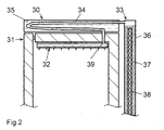
- the buffer store 30 is located above the evaporator 32.
- the working medium steam line 34 runs from the sorbent container 33 through the buffer store 30 in order to be able to effectively dissipate the heat of liquefaction from its water content 35.
- the part of the working medium steam line 34 which can emit heat to the water content 35 consequently also has the function of the condenser.
- the working medium steam line 34 is arranged at an incline, so that the condensate 39 can flow directly into the evaporator 32 during the desorption phase without additional precautions, following gravity.
- the sorption container 33 consists of an internal heating cartridge 38 and a sorbent filling 37, which is enclosed by a cylindrical sorber sleeve 36. This also does not require thermal insulation since the heat losses due to the short desorption phase and the large temperature gradient within the sorbent filling 37 are low.
- the operating mode of the cooling apparatus according to FIG. 2 is identical to the operating mode of the apparatus according to FIG. 1 described above. The only difference is that the condensate 39 does not remain in the condenser, but can already flow into the evaporator 32 during the desorption phase.
Landscapes
- Engineering & Computer Science (AREA)
- Physics & Mathematics (AREA)
- Mechanical Engineering (AREA)
- Thermal Sciences (AREA)
- General Engineering & Computer Science (AREA)
- Chemical & Material Sciences (AREA)
- Combustion & Propulsion (AREA)
- Sorption Type Refrigeration Machines (AREA)
- Devices That Are Associated With Refrigeration Equipment (AREA)
- Solid-Sorbent Or Filter-Aiding Compositions (AREA)
Abstract
Description
Als Pufferspeicher sind prinzipiell alle aus der Wärmespeichertechnik bekannten Speichermedien wie Flüssigkeiten, Phasenwechselmaterialien (PCM) und Feststoffe geeignet. Preiswert ist Wasser, das auch eine hohe Wärmeübertragungsleistung ermöglicht. Der Verflüssiger kann dabei direkt in einem Wasserspeicher integriert sein. Über die äußere Oberfläche des Tanks wird dann die gepufferte Wärme während der langen Adsorptionsphase ohne zusätzliche Wärmetauscher an die Umgebungsluft abgeführt.
Die Verwendung von Wasser als Arbeitsmittel gestattet es, den erforderlichen Regelungsaufwand auf ein Minimum zu reduzieren. Beim Verdampfen von Wasser unter Vakuum kühlt sich die Wasseroberfläche auf 0°C ab und gefriert bei fortgesetzter Verdampfung zu Eis. Die Eisschicht kann vorteilhaft zur Regelung der Temperatur des zu kühlenden Mediums benutzt werden. Bei geringer Wärmezufuhr wächst die Eisschicht, bei sehr großer Wärmezufuhr schmilzt sie ab. Durch die Eisbildung wird die Wärmeübertragung vom zu kühlenden Medium in den Verdampfer reduziert, so dass sich das Medium nicht unter 0°C abkühlen kann. Bei fortgesetzter Verdampfung kann der komplette Wasservorrat im Verdampfer vereisen. Die Sublimationstemperatur der Eisschicht sinkt anschließend unter 0°C ab.
Dem wässerigen Verdampferinhalt können auch den Gefrierpunkt absenkende Stoffe beigemischt sein, wenn die Temperatur des zu kühlenden Mediums unter 0°C abgesenkt werden soll.
Feste Sorptionsmittel lassen sich zudem zu Formkörpern verarbeiten. Ein einzelner oder einige wenige Formkörper können eine komplette, preisgünstige Sorptionsmittelfüllung bilden.
Unter der Decke des Kühlschrankes 1 ist ein Verdampfer 4 angeordnet, aus dem das Arbeitsmittel Wasser 5 verdampft. Der Verdampfer 4 ist über eine Arbeitsmitteldampfleitung 9 mit einem Sorptionsmittelbehälter 12 und über eine weitere Verbindungsleitung 10 mit einem Verflüssiger 13 verbunden. Der Verdampfer 4 ist auf seiner unteren Innenfläche mit einem saugfähiges Faservlies 6 beschichtet, welches das Arbeitsmittel Wasser homogen über die Wärme aufnehmende Oberfläche verteilt. Außen enthält er mehrere Kühlrippen 7, die Wärme aus dem zu kühlenden Medium Luft aufnehmen. Unterhalb der Kühlrippen 7 ist eine Lage Kälte speichernde Elemente 8 eingelegt, die Wasser enthalten und die auch vereisen können. Vor der Mündung der Arbeitsmitteldampfleitung 9 ist ein Bi-Metall-Element 23 angeordnet, das bei sinkenden Verdampfertemperaturen die Austrittsöffnung zum Sorptionsmittelbehälter verengt. Der mit Wärmetauscherrippen 15 versehene Verflüssiger 13 liegt im unteren Bereich eines Pufferspeichers 14, der mit Wasser 16 aufgefüllt ist. Der Sorptionsmittelbehälter 12 besteht aus zwei metallischen Sorberhüllen 17, die in der Mitte eine elektrische Heizung 18 einbetten. Die Sorberhüllen 17 enthalten jeweils eine Sorptionsmittelfüllung 19, die aus Zeolithformkörpern aufgebaut ist.
Ein Regler 20 steuert den Betrieb der Heizung 18 , abhängig von der Temperatur der Kühlschrankluft und der Temperatur der Sorptionsmittelfüllung 19. Eingangsgrößen in den Regler 20 sind die Lufttemperaturen im Kühlschrank, die über einen Temperatursensor 21 erfasst werden und die Zeolithtemperatur, die von einem Zeolith-Temperaturfühler 22 gemeldet wird.
Auch die mit der Umgebungsluft in Kontakt stehenden Sorptionsbehälter-Hüllen 17 geben während der Desorptionsphase Wärme ab. Da diese Phase aber erfindungsgemäß kurz gehalten werden kann und die Wärmeverluste relativ zur hohen Heizleistung gering sind, kann auf eine thermische Isolierung der äußeren Sorptionsbehälter-Hüllen 17 verzichtet werden. Zudem bildet sich innerhalb der Sorptionsmittelfüllung 19 ein relativ starker Temperaturgradient aus. So sind nahe der elektrischen Heizung 18 Temperaturen bis 400 °C messbar, während die Zeolithtemperaturen im Kontakt zu den außenliegenden Sorptionsbehälter-Hüllen 17 nur 140 °C heiß werden. Die Wärmeverluste an die Umgebung sind von diesem niedrigen Temperaturniveau deutlich geringer. Zudem treten diese Temperaturen lediglich am Ende der Desorptionsphase auf. Mit dem Erreichen der Desorptions-Endtemperatur wird die Beheizung abgestellt. Der Pufferspeicher hat zu diesem Zeitpunkt seine höchste Temperatur. Diese sinkt nunmehr während der folgenden Adsorptionsphase kontinuierlich ab, da über die Behälterwände langsam Wärme an die Umgebung abfließt.
Auch über die nicht thermisch isolierten Sorptionsbehälter-Hüllen 17 fließt weiterhin Wärme an die vorbeiströmende Umgebungsluft ab. Die Temperatur der Sorptionsmittelfüllung 19 sinkt dadurch und Arbeitsmitteldampf strömt zurück in den Sorptionsmittelbehälter 12. Der Dampfdruck im Verdampfer 4 nimmt daraufhin ab bis das Kondensat aus dem Verflüssiger hochgesaugt wird. Alsbald befindet sich die gesamte flüssige Arbeitsmittelmenge im Verdampfer 4. Bei fortgesetzter Abkühlung der Sorptionsmittelfüllung 19 wird im Laufe der Adsorptionsphase auch diese Wassermasse im Verdampfer unter Aufnahme der Verdampfungswärme verdampfen. Bei Verdampfungstemperaturen unterhalb des Gefrierpunktes wird nach und nach die verbliebene Wassermenge vereisen. Ein mögliches Abkühlen weit unter den Gefrierpunkt verhindert das Bi-Metallelement 23, das die Einströmungsöffnung in die Arbeitsmitteldampfleitung 9 verengt. Das Ende der Adsorptionsphase ist erreicht, wenn der Regler 20 eine zu hohe Lufttemperatur im Kühlschrank registriert. Durch Aufheizung der Sorptionsmittelfüllung 19 beginnt die Desorptionsphase dann von vorne.
Die Betriebsweise des Kühlapparates nach Fig. 2 verläuft identisch zu der weiter oben beschriebenen Betriebsweise des Apparates gemäß Fig. 1. Einziger Unterschied ist, dass das Kondensat 39 nicht im Verflüssiger verbleibt, sondern bereits während der Desorptionsphase in den Verdampfer 32 abfließen kann.
Claims (13)
- Adsorptions-Kühlapparat mit einem intermittierend beheizten Sorptionsmittelbehälter (12), der ein Sorptionsmittel (19) enthält, das während einer Adsorptionsphase ein Arbeitsmittel exotherm sorbiert und während einer folgenden Desorptionsphase unter Wärmezufuhr bei höheren Temperaturen wieder desorbiert, mit einem Verflüssiger (4), der über eine Verbindungsleitung (10) verflüssigtes Arbeitsmittel in den Verdampfer (4) ableitet, der wiederum mit dem Sorptionsmittel (19) über eine Arbeitsmitteldampfleitung (9) in Verbindung steht und während der Adsorptionsphase Wärme von einem zu kühlenden Medium aufnimmt,
dadurch gekennzeichnet, dass
der Verflüssiger (4) an einen Pufferspeicher (14) gekoppelt ist, der zumindest einen Teil der Verflüssigungswärme des Arbeitsmitteldampfes puffert und die gespeicherte Wärme auch während der Adsorptionsphase an die Umgebung wieder abführen kann. - Adsorptions-Kühlapparat nach einem der vorangehenden Ansprüche,
dadurch gekennzeichnet, dass
der Verdampfer (4) so angeordnet ist, dass er während der Desorptionsphase relativ wenig Wärme an das zu kühlende Medium abgibt. - Adsorptions-Kühlapparat nach einem der vorangehenden Ansprüche,
dadurch gekennzeichnet, dass
der Verdampfer (4) im oberen Bereich des zu kühlenden Mediums angeordnet ist und dass das sich während der Desorptionsphase erwärmende Medium auf Grund der geringeren Dichte nicht mit dem darunter befindlichen, kühleren Medium vermischt. - Adsorptions-Kühlapparat nach einem der vorangehenden Ansprüche,
dadurch gekennzeichnet, dass
unterhalb des Verdampfers (4) ein Kälte speicherndes Element (8) oder ein Strahlungsschirm angeordnet ist. - Adsorptions-Kühlapparat nach einem der vorangehenden Ansprüche,
dadurch gekennzeichnet, dass
das zu kühlende Medium mittels Absperr-Vorrichtungen gehindert wird, während der Desorptionsphase mit dem bereits gekühlten Medium Wärme auszutauschen. - Adsorptions-Kühlapparat nach einem der vorangehenden Ansprüche,
dadurch gekennzeichnet, dass
die während der Desorptionsphase zugeführte Desorptionswärme aus einem Brenner zugeführt wird. - Adsorptions-Kühlapparat nach einem der vorangehenden Ansprüche,
dadurch gekennzeichnet, dass
das Sorptionsmittel Zeolith und das Arbeitsmittel Wasser enthält. - Adsorptions-Kühlapparat nach einem der vorangehenden Ansprüche,
dadurch gekennzeichnet, dass
das Kondensat in einem Kondensatpuffer auf einem tieferen Niveau gesammelt wird und am Anfang der Adsorptionsphase in das höher gelegene Niveau des Verdampfers (4) gesaugt wird. - Adsorptions-Kühlapparat nach einem der vorangehenden Ansprüche,
dadurch gekennzeichnet, dass
der Verdampfer (4) Benetzungsmittel (6) enthält, die eine homogene Verteilung des flüssigen Arbeitsmittels innerhalb des Verdampfers bewirken. - Adsorptions-Kühlapparat nach einem der vorangehenden Ansprüche,
dadurch gekennzeichnet, dass
die Arbeitsmitteldampfleitung (9) ein Regelelement enthält, das den Strömungsquerschnitt bei zu tiefen Verdampfertemperaturen verengt. - Adsorptions-Kühlapparat nach Anspruch 10,
dadurch gekennzeichnet, dass
das Regelelement ein Bimetall-Element (23) enthält. - Verfahren zum Betrieb eines Adsorptions-Kühlapparates mit einem intermittierend beheizten Sorptionsbehälter, der ein Sorptionsmittel enthält, das während einer Adsorptionsphase ein Arbeitsmittel exotherm sorbiert und während einer folgenden Desorptionsphase unter Wärmezufuhr bei höheren Temperaturen wieder desorbiert, mit einem angeschlossenen Verflüssiger, der über eine Kondensatleitung verflüssigtes Arbeitsmittel in einen Verdampfer ableitet, der wiederum mit dem Sorptionsmittel über eine Arbeitsmitteldampfleitung in Verbindung steht,
dadurch gekennzeichnet, dass
die Desorptionsphase weniger als ein Drittel der Zeit der Adsorptionsphase beträgt und die Verflüssigungswärme während der Desorptionsphase von einem Wärmespeichermedium gepuffert wird und die gepufferte Wärme größtenteils während der Adsorptionsphase wieder abgeführt wird. - Verfahren zum Betrieb eines Adsorptions-Kühlapparates nach Anspruch 12,
dadurch gekennzeichnet, dass
während der Desorptionsphase, verursacht durch eine hohe Heizleistung, innerhalb des Sorptionsmittels ein Temperaturgradient von über 100 K zwischen der Wärme aufnehmenden Fläche und der Wärme abgebenden Fläche entsteht.
Applications Claiming Priority (2)
| Application Number | Priority Date | Filing Date | Title |
|---|---|---|---|
| DE10250510A DE10250510A1 (de) | 2002-10-29 | 2002-10-29 | Adsorptions-Kühlapparat mit Pufferspeicher |
| DE10250510 | 2002-10-29 |
Publications (3)
| Publication Number | Publication Date |
|---|---|
| EP1416233A2 true EP1416233A2 (de) | 2004-05-06 |
| EP1416233A3 EP1416233A3 (de) | 2005-09-21 |
| EP1416233B1 EP1416233B1 (de) | 2007-04-25 |
Family
ID=32087289
Family Applications (1)
| Application Number | Title | Priority Date | Filing Date |
|---|---|---|---|
| EP03017429A Expired - Lifetime EP1416233B1 (de) | 2002-10-29 | 2003-08-01 | Adsorptions-Kühlapparat mit Pufferspeicher |
Country Status (6)
| Country | Link |
|---|---|
| US (1) | US6820441B2 (de) |
| EP (1) | EP1416233B1 (de) |
| JP (1) | JP2004150792A (de) |
| AT (1) | ATE360787T1 (de) |
| DE (2) | DE10250510A1 (de) |
| ES (1) | ES2283688T3 (de) |
Cited By (6)
| Publication number | Priority date | Publication date | Assignee | Title |
|---|---|---|---|---|
| WO2008015608A3 (en) * | 2006-08-04 | 2008-04-10 | Koninkl Philips Electronics Nv | A domestic beverage dispensing apparatus comprising an adsorbent cooling device |
| EP2728281A4 (de) * | 2011-06-28 | 2015-03-25 | Fujitsu Ltd | Adsorptionswärmepumpe mit plattenventil und informationsverarbeitungssystem |
| WO2018029522A1 (de) * | 2016-08-09 | 2018-02-15 | Rep Ip Ag | Transportbehälter |
| EP3351873A1 (de) | 2017-01-20 | 2018-07-25 | Coolar UG (beschränkte Haftung) | Sorptionskältevorrichtung |
| EP3686517A1 (de) * | 2016-08-09 | 2020-07-29 | Rep Ip Ag | Transportbehälter |
| US12366401B2 (en) | 2019-02-07 | 2025-07-22 | Rep Ip Ag | Transport container |
Families Citing this family (15)
| Publication number | Priority date | Publication date | Assignee | Title |
|---|---|---|---|---|
| FR2851329B1 (fr) * | 2003-02-17 | 2006-02-03 | Airbus | Procede de maintien au froid d'aliments a bord d'aeronefs et moyen de mise en oeuvre |
| DE10344455A1 (de) | 2003-09-25 | 2005-05-12 | Zeolith Tech | Verfahren und Vorrichtungen zum schnellen Erstarren wasserhaltiger Substanzen |
| DE102005034297A1 (de) * | 2005-02-25 | 2006-08-31 | Zeo-Tech Zeolith-Technologie Gmbh | Sorptions-Kühlelement mit gasdichter Folie |
| EP1967799B1 (de) * | 2007-03-05 | 2012-11-21 | ZEO-TECH Zeolith Technologie GmbH | Sorptions-Kühlelement mit Regelorgan und zusätzlicher Wärmequelle |
| EP2006616A2 (de) * | 2007-06-19 | 2008-12-24 | ZEO-TECH Zeolith Technologie GmbH | Flexible Sorptions-Kühlelemente |
| DE102009010594A1 (de) | 2009-02-25 | 2010-08-26 | Enymotion Gmbh | Brennstoffzellensystem und Verfahren zum Anfahren und Betrieb eines solchen Brennstoffzellensystems |
| US9175888B2 (en) | 2012-12-03 | 2015-11-03 | Whirlpool Corporation | Low energy refrigerator heat source |
| US9657982B2 (en) | 2013-03-29 | 2017-05-23 | Tokitae Llc | Temperature-controlled medicinal storage devices |
| CN105378396A (zh) * | 2013-03-29 | 2016-03-02 | 脱其泰有限责任公司 | 温控存储系统 |
| US10941971B2 (en) | 2013-03-29 | 2021-03-09 | Tokitae Llc | Temperature-controlled portable cooling units |
| US11105556B2 (en) | 2013-03-29 | 2021-08-31 | Tokitae, LLC | Temperature-controlled portable cooling units |
| US9170053B2 (en) | 2013-03-29 | 2015-10-27 | Tokitae Llc | Temperature-controlled portable cooling units |
| DE102014225411A1 (de) * | 2014-12-10 | 2016-06-16 | Mahle International Gmbh | Sorptionsmodul |
| US20210310711A1 (en) | 2019-05-31 | 2021-10-07 | Gobi Technologies Inc. | Temperature-controlled sorption system |
| WO2020243637A1 (en) * | 2019-05-31 | 2020-12-03 | Gobi Technologies Inc. | Thermal regulation system |
Family Cites Families (30)
| Publication number | Priority date | Publication date | Assignee | Title |
|---|---|---|---|---|
| GB317767A (en) * | 1928-08-21 | 1930-11-21 | Wulff Berzelius Normelli | Improvements in periodic absorption refrigerating apparatus |
| BE380895A (de) * | 1929-09-19 | |||
| DE609104C (de) * | 1933-06-16 | 1935-02-07 | H C Edmund Altenkirch Dr Ing | Verfahren zum Betriebe einer Absorptionskaeltemaschine |
| GB506846A (en) * | 1937-01-27 | 1939-06-06 | Ivar Amundsen | Refrigerating plant of the absorption type |
| DE3207656A1 (de) * | 1982-02-15 | 1983-08-25 | Hieronimi, Ulrich, 8000 München | Sorptionsapparate und verfahren fuer ihren betrieb |
| FR2539854A1 (fr) * | 1983-04-22 | 1984-07-27 | Cetiat | Installation de refrigeration par adsorption sur un adsorbant solide et procede pour sa mise en oeuvre |
| DE3342985A1 (de) * | 1983-11-28 | 1985-06-13 | Fritz Dipl.-Ing. Kaubek | Kontinuierlichwirkende sorptionsapparate und verfahren zu deren betrieb |
| DE3347700C2 (de) * | 1983-12-31 | 1994-07-07 | Zeolith Tech | Zeolithformling mit hoher Wärmeleitung und Verfahren zur Herstellung |
| DE3413349C2 (de) * | 1984-04-09 | 1986-09-25 | Fritz Dipl.-Ing. Kaubek | Verfahren und Vorrichtung zum Heizen mit einer periodischen Adsorptionsspeicher-Wärmepumpe |
| DE3425419C2 (de) * | 1984-07-10 | 1993-12-09 | Zeolith Tech | Adiabatische Heiz- und Kühlvorrichtungen nach dem Adsorptionsprinzip |
| DE3521484A1 (de) * | 1985-06-14 | 1986-12-18 | Fritz Dipl.-Ing. Kaubek | Adsorptionskuehler |
| DE3837872A1 (de) * | 1988-11-08 | 1990-05-10 | Zeolith Tech | Sorptionskuehlsystem |
| DE3837880A1 (de) * | 1988-11-08 | 1990-05-10 | Zeolith Tech | Kuehlbehaelter fuer einen sorptionsapparat |
| DE3901558A1 (de) * | 1989-01-20 | 1990-07-26 | Zeolith Tech | Sorptionsbehaelter fuer feste sorptionsmittel |
| DE4003107A1 (de) * | 1990-02-02 | 1991-08-08 | Zeolith Tech | Eiserzeuger nach dem sorptionsprinzip |
| DE4121131A1 (de) * | 1991-06-26 | 1993-01-07 | Zeolith Tech | Sorptionsmittelbehaelter-anordnung und sorptionsverfahren mit regenerativem waermetausch |
| DE4126960A1 (de) * | 1991-08-14 | 1993-02-18 | Zeolith Tech | Sorptionsapparat zum kuehlen und/oder heizen |
| DE4138114A1 (de) * | 1991-11-19 | 1993-05-27 | Zeolith Tech | Kuehlvorrichtung und kuehlverfahren zur kuehlung eines mediums innerhalb eines gefaesses |
| EP0577869B1 (de) * | 1992-07-06 | 1997-01-08 | ZEO-TECH Zeolith Technologie GmbH | Kühlsystem mit einer vakuumdichten Arbeitsmitteldampf-Sammelleitung |
| US5272891A (en) * | 1992-10-21 | 1993-12-28 | Erickson Donald C | Intermittent sorption cycle with integral thermosyphon |
| DE4243817A1 (de) * | 1992-12-23 | 1994-06-30 | Zeolith Tech | Adapter für ein Sorptionssystem und Verfahren zur Verwendung dieses Adapters |
| DE4243816A1 (de) * | 1992-12-23 | 1994-06-30 | Zeolith Tech | Sorptionsmittel-Patrone |
| EP0731324B1 (de) * | 1993-11-29 | 2003-04-02 | Mayekawa Mfg Co.Ltd. | Adsorbtionskältevorrichtung und Verfahren zur Regelung der Kälteleistung derselben. |
| EP0781393B1 (de) * | 1994-09-12 | 1999-12-15 | Electrolux Leisure Appliances Ag | Sorptions-kühlaggregat |
| WO1996011368A1 (de) * | 1994-10-06 | 1996-04-18 | Electrolux Leisure Appliances Ab | Kühlvorrichtung mit einer intermittierend arbeitenden kühleinheit |
| FR2774460B1 (fr) * | 1998-02-03 | 2000-03-24 | Elf Aquitaine | Procede de gestion d'une reaction thermochimique ou d'une adsorption solide-gaz |
| DE19922848A1 (de) * | 1999-05-19 | 2000-11-23 | Zeolith Tech | Vorrichtung und Verfahren zum Kühlen einer Flüssigkeit in einem Behälter |
| DE10016352A1 (de) * | 2000-04-03 | 2001-10-04 | Zeolith Tech | Sorptionskühler |
| DE10028030A1 (de) * | 2000-06-09 | 2001-12-13 | Zeolith Tech | Sorptionsvorrichtung zum Heizen und Kühlen von Gasströmen |
| US6601404B1 (en) * | 2001-08-17 | 2003-08-05 | Nanopore, Inc. | Cooling device |
-
2002
- 2002-10-29 DE DE10250510A patent/DE10250510A1/de not_active Withdrawn
-
2003
- 2003-08-01 ES ES03017429T patent/ES2283688T3/es not_active Expired - Lifetime
- 2003-08-01 EP EP03017429A patent/EP1416233B1/de not_active Expired - Lifetime
- 2003-08-01 AT AT03017429T patent/ATE360787T1/de not_active IP Right Cessation
- 2003-08-01 DE DE50307123T patent/DE50307123D1/de not_active Expired - Lifetime
- 2003-09-08 US US10/657,668 patent/US6820441B2/en not_active Expired - Fee Related
- 2003-10-28 JP JP2003367706A patent/JP2004150792A/ja active Pending
Cited By (12)
| Publication number | Priority date | Publication date | Assignee | Title |
|---|---|---|---|---|
| WO2008015608A3 (en) * | 2006-08-04 | 2008-04-10 | Koninkl Philips Electronics Nv | A domestic beverage dispensing apparatus comprising an adsorbent cooling device |
| EP2728281A4 (de) * | 2011-06-28 | 2015-03-25 | Fujitsu Ltd | Adsorptionswärmepumpe mit plattenventil und informationsverarbeitungssystem |
| US9212837B2 (en) | 2011-06-28 | 2015-12-15 | Fujitsu Limited | Adsorption-type heat pump using seat valve and information processing system |
| WO2018029522A1 (de) * | 2016-08-09 | 2018-02-15 | Rep Ip Ag | Transportbehälter |
| EP3686517A1 (de) * | 2016-08-09 | 2020-07-29 | Rep Ip Ag | Transportbehälter |
| US11187450B2 (en) | 2016-08-09 | 2021-11-30 | Rep Ip Ag | Transport container |
| US11614267B2 (en) | 2016-08-09 | 2023-03-28 | Rep Ip Ag | Transport container |
| US11920832B2 (en) | 2016-08-09 | 2024-03-05 | Rep Ip Ag | Transport container |
| EP3351873A1 (de) | 2017-01-20 | 2018-07-25 | Coolar UG (beschränkte Haftung) | Sorptionskältevorrichtung |
| DE102017101058A1 (de) | 2017-01-20 | 2018-07-26 | Coolar UG (haftungsbeschränkt) | Sorptionskältevorrichtung |
| US10704811B2 (en) | 2017-01-20 | 2020-07-07 | Coolar UG | Sorption cooling device |
| US12366401B2 (en) | 2019-02-07 | 2025-07-22 | Rep Ip Ag | Transport container |
Also Published As
| Publication number | Publication date |
|---|---|
| EP1416233B1 (de) | 2007-04-25 |
| ES2283688T3 (es) | 2007-11-01 |
| ATE360787T1 (de) | 2007-05-15 |
| EP1416233A3 (de) | 2005-09-21 |
| JP2004150792A (ja) | 2004-05-27 |
| DE10250510A1 (de) | 2004-05-19 |
| US20040079106A1 (en) | 2004-04-29 |
| US6820441B2 (en) | 2004-11-23 |
| DE50307123D1 (de) | 2007-06-06 |
Similar Documents
| Publication | Publication Date | Title |
|---|---|---|
| EP1416233A2 (de) | Adsorptions-Kühlapparat mit Pufferspeicher | |
| EP1443288A2 (de) | Kühl-Container mit Adsorptions-Kühlapparat | |
| EP0368111B1 (de) | Sorptionskühlsystem | |
| EP1143210B1 (de) | Sorptionskühler | |
| EP0205167B2 (de) | Adsorptionskühler | |
| EP1054222B1 (de) | Vorrichtung und Verfahren zum Kühlen einer Flüssigkeit in einem Behälter | |
| DE3413349C2 (de) | Verfahren und Vorrichtung zum Heizen mit einer periodischen Adsorptionsspeicher-Wärmepumpe | |
| DE4019669A1 (de) | Adsorptionsthermischer speicherapparat und adsorptionsthermisches speichersystem denselben enthaltend | |
| DE10028030A1 (de) | Sorptionsvorrichtung zum Heizen und Kühlen von Gasströmen | |
| DE10330104A1 (de) | Kühlsystem mit Adsorptions-Kühlgerät | |
| EP0733190B1 (de) | Kühlvorrichtung mit einer intermittierend arbeitenden kühleinheit | |
| DE4333829A1 (de) | Verfahren und Anlage zur Speicherung von Wärmeenergie | |
| EP1519125A2 (de) | Verfahren und Vorrichtungen zum schnellen Erstarren wasserhaltiger Substanzen | |
| DE19908666B4 (de) | Sorptionswärmepumpe/-Kältemaschine mit Erwärmung des bisherigen Adsorbers auf Desorptionstemperatur durch Adsorption | |
| EP2697580B1 (de) | Verdunstungsvorrichtung für ein kältegerät | |
| DE3604909A1 (de) | Waermeuebertragungselement fuer verdampfer | |
| EP2637883B1 (de) | Abgas angetriebene adsorptionskältemaschine | |
| EP2281157A1 (de) | Kältegerät, insbesondere haushaltskältegerät umfassend einen verflüssiger mit wärmespeicherelementen | |
| DE102011008278A1 (de) | Verfahren und Vorrichtung zur Gebäudeklimatisierung | |
| DE102016106091A1 (de) | Klimaanlage mit Vakuumeinschluss | |
| DE29908469U1 (de) | Thermische Batterie | |
| DE4431388C2 (de) | Vorrichtung zur Aufnahme und Abgabe von Wärmeenergie | |
| WO2019243566A1 (de) | Verfahren zum betrieb einer wärmepumpe und eine kältemaschine | |
| DE102005056245A1 (de) | Kühlvorrichtung und Verfahren zu deren Betrieb | |
| DE102008020605B4 (de) | Heiz- und Kühlanordnung |
Legal Events
| Date | Code | Title | Description |
|---|---|---|---|
| PUAI | Public reference made under article 153(3) epc to a published international application that has entered the european phase |
Free format text: ORIGINAL CODE: 0009012 |
|
| AK | Designated contracting states |
Kind code of ref document: A2 Designated state(s): AT BE BG CH CY CZ DE DK EE ES FI FR GB GR HU IE IT LI LU MC NL PT RO SE SI SK TR |
|
| AX | Request for extension of the european patent |
Extension state: AL LT LV MK |
|
| PUAL | Search report despatched |
Free format text: ORIGINAL CODE: 0009013 |
|
| AK | Designated contracting states |
Kind code of ref document: A3 Designated state(s): AT BE BG CH CY CZ DE DK EE ES FI FR GB GR HU IE IT LI LU MC NL PT RO SE SI SK TR |
|
| AX | Request for extension of the european patent |
Extension state: AL LT LV MK |
|
| 17P | Request for examination filed |
Effective date: 20060310 |
|
| AKX | Designation fees paid |
Designated state(s): AT BE BG CH CY CZ DE DK EE ES FI FR GB GR HU IE IT LI LU MC NL PT RO SE SI SK TR |
|
| GRAP | Despatch of communication of intention to grant a patent |
Free format text: ORIGINAL CODE: EPIDOSNIGR1 |
|
| GRAS | Grant fee paid |
Free format text: ORIGINAL CODE: EPIDOSNIGR3 |
|
| GRAA | (expected) grant |
Free format text: ORIGINAL CODE: 0009210 |
|
| AK | Designated contracting states |
Kind code of ref document: B1 Designated state(s): AT BE BG CH CY CZ DE DK EE ES FI FR GB GR HU IE IT LI LU MC NL PT RO SE SI SK TR |
|
| PG25 | Lapsed in a contracting state [announced via postgrant information from national office to epo] |
Ref country code: FI Free format text: LAPSE BECAUSE OF FAILURE TO SUBMIT A TRANSLATION OF THE DESCRIPTION OR TO PAY THE FEE WITHIN THE PRESCRIBED TIME-LIMIT Effective date: 20070425 |
|
| REG | Reference to a national code |
Ref country code: GB Ref legal event code: FG4D Free format text: NOT ENGLISH |
|
| REG | Reference to a national code |
Ref country code: IE Ref legal event code: FG4D Free format text: LANGUAGE OF EP DOCUMENT: GERMAN |
|
| REG | Reference to a national code |
Ref country code: CH Ref legal event code: EP |
|
| REF | Corresponds to: |
Ref document number: 50307123 Country of ref document: DE Date of ref document: 20070606 Kind code of ref document: P |
|
| PG25 | Lapsed in a contracting state [announced via postgrant information from national office to epo] |
Ref country code: SE Free format text: LAPSE BECAUSE OF FAILURE TO SUBMIT A TRANSLATION OF THE DESCRIPTION OR TO PAY THE FEE WITHIN THE PRESCRIBED TIME-LIMIT Effective date: 20070725 |
|
| GBT | Gb: translation of ep patent filed (gb section 77(6)(a)/1977) |
Effective date: 20070724 |
|
| PG25 | Lapsed in a contracting state [announced via postgrant information from national office to epo] |
Ref country code: PT Free format text: LAPSE BECAUSE OF FAILURE TO SUBMIT A TRANSLATION OF THE DESCRIPTION OR TO PAY THE FEE WITHIN THE PRESCRIBED TIME-LIMIT Effective date: 20070925 |
|
| ET | Fr: translation filed | ||
| NLV1 | Nl: lapsed or annulled due to failure to fulfill the requirements of art. 29p and 29m of the patents act | ||
| REG | Reference to a national code |
Ref country code: ES Ref legal event code: FG2A Ref document number: 2283688 Country of ref document: ES Kind code of ref document: T3 |
|
| REG | Reference to a national code |
Ref country code: IE Ref legal event code: FD4D |
|
| PG25 | Lapsed in a contracting state [announced via postgrant information from national office to epo] |
Ref country code: SI Free format text: LAPSE BECAUSE OF FAILURE TO SUBMIT A TRANSLATION OF THE DESCRIPTION OR TO PAY THE FEE WITHIN THE PRESCRIBED TIME-LIMIT Effective date: 20070425 Ref country code: IE Free format text: LAPSE BECAUSE OF FAILURE TO SUBMIT A TRANSLATION OF THE DESCRIPTION OR TO PAY THE FEE WITHIN THE PRESCRIBED TIME-LIMIT Effective date: 20070425 Ref country code: BG Free format text: LAPSE BECAUSE OF FAILURE TO SUBMIT A TRANSLATION OF THE DESCRIPTION OR TO PAY THE FEE WITHIN THE PRESCRIBED TIME-LIMIT Effective date: 20070725 Ref country code: CZ Free format text: LAPSE BECAUSE OF FAILURE TO SUBMIT A TRANSLATION OF THE DESCRIPTION OR TO PAY THE FEE WITHIN THE PRESCRIBED TIME-LIMIT Effective date: 20070425 Ref country code: NL Free format text: LAPSE BECAUSE OF FAILURE TO SUBMIT A TRANSLATION OF THE DESCRIPTION OR TO PAY THE FEE WITHIN THE PRESCRIBED TIME-LIMIT Effective date: 20070425 Ref country code: DK Free format text: LAPSE BECAUSE OF FAILURE TO SUBMIT A TRANSLATION OF THE DESCRIPTION OR TO PAY THE FEE WITHIN THE PRESCRIBED TIME-LIMIT Effective date: 20070425 |
|
| BERE | Be: lapsed |
Owner name: ZEO-TECH ZEOLITH TECHNOLOGIE G.M.B.H. Effective date: 20070831 |
|
| PG25 | Lapsed in a contracting state [announced via postgrant information from national office to epo] |
Ref country code: SK Free format text: LAPSE BECAUSE OF FAILURE TO SUBMIT A TRANSLATION OF THE DESCRIPTION OR TO PAY THE FEE WITHIN THE PRESCRIBED TIME-LIMIT Effective date: 20070425 |
|
| PLBE | No opposition filed within time limit |
Free format text: ORIGINAL CODE: 0009261 |
|
| STAA | Information on the status of an ep patent application or granted ep patent |
Free format text: STATUS: NO OPPOSITION FILED WITHIN TIME LIMIT |
|
| 26N | No opposition filed |
Effective date: 20080128 |
|
| REG | Reference to a national code |
Ref country code: CH Ref legal event code: PL |
|
| PG25 | Lapsed in a contracting state [announced via postgrant information from national office to epo] |
Ref country code: GR Free format text: LAPSE BECAUSE OF FAILURE TO SUBMIT A TRANSLATION OF THE DESCRIPTION OR TO PAY THE FEE WITHIN THE PRESCRIBED TIME-LIMIT Effective date: 20070726 Ref country code: LI Free format text: LAPSE BECAUSE OF NON-PAYMENT OF DUE FEES Effective date: 20070831 Ref country code: MC Free format text: LAPSE BECAUSE OF NON-PAYMENT OF DUE FEES Effective date: 20070831 Ref country code: CH Free format text: LAPSE BECAUSE OF NON-PAYMENT OF DUE FEES Effective date: 20070831 |
|
| PG25 | Lapsed in a contracting state [announced via postgrant information from national office to epo] |
Ref country code: RO Free format text: LAPSE BECAUSE OF FAILURE TO SUBMIT A TRANSLATION OF THE DESCRIPTION OR TO PAY THE FEE WITHIN THE PRESCRIBED TIME-LIMIT Effective date: 20070425 |
|
| PG25 | Lapsed in a contracting state [announced via postgrant information from national office to epo] |
Ref country code: BE Free format text: LAPSE BECAUSE OF NON-PAYMENT OF DUE FEES Effective date: 20070831 |
|
| PG25 | Lapsed in a contracting state [announced via postgrant information from national office to epo] |
Ref country code: AT Free format text: LAPSE BECAUSE OF NON-PAYMENT OF DUE FEES Effective date: 20070801 |
|
| PG25 | Lapsed in a contracting state [announced via postgrant information from national office to epo] |
Ref country code: EE Free format text: LAPSE BECAUSE OF FAILURE TO SUBMIT A TRANSLATION OF THE DESCRIPTION OR TO PAY THE FEE WITHIN THE PRESCRIBED TIME-LIMIT Effective date: 20070425 |
|
| PG25 | Lapsed in a contracting state [announced via postgrant information from national office to epo] |
Ref country code: CY Free format text: LAPSE BECAUSE OF FAILURE TO SUBMIT A TRANSLATION OF THE DESCRIPTION OR TO PAY THE FEE WITHIN THE PRESCRIBED TIME-LIMIT Effective date: 20070425 |
|
| PG25 | Lapsed in a contracting state [announced via postgrant information from national office to epo] |
Ref country code: LU Free format text: LAPSE BECAUSE OF NON-PAYMENT OF DUE FEES Effective date: 20070801 |
|
| PG25 | Lapsed in a contracting state [announced via postgrant information from national office to epo] |
Ref country code: HU Free format text: LAPSE BECAUSE OF FAILURE TO SUBMIT A TRANSLATION OF THE DESCRIPTION OR TO PAY THE FEE WITHIN THE PRESCRIBED TIME-LIMIT Effective date: 20071026 |
|
| PGFP | Annual fee paid to national office [announced via postgrant information from national office to epo] |
Ref country code: ES Payment date: 20090821 Year of fee payment: 7 Ref country code: FR Payment date: 20090819 Year of fee payment: 7 |
|
| PGFP | Annual fee paid to national office [announced via postgrant information from national office to epo] |
Ref country code: DE Payment date: 20090819 Year of fee payment: 7 Ref country code: GB Payment date: 20090821 Year of fee payment: 7 Ref country code: TR Payment date: 20090724 Year of fee payment: 7 |
|
| PGFP | Annual fee paid to national office [announced via postgrant information from national office to epo] |
Ref country code: IT Payment date: 20090824 Year of fee payment: 7 |
|
| GBPC | Gb: european patent ceased through non-payment of renewal fee |
Effective date: 20100801 |
|
| REG | Reference to a national code |
Ref country code: FR Ref legal event code: ST Effective date: 20110502 |
|
| PG25 | Lapsed in a contracting state [announced via postgrant information from national office to epo] |
Ref country code: IT Free format text: LAPSE BECAUSE OF NON-PAYMENT OF DUE FEES Effective date: 20100801 |
|
| REG | Reference to a national code |
Ref country code: DE Ref legal event code: R119 Ref document number: 50307123 Country of ref document: DE Effective date: 20110301 |
|
| PG25 | Lapsed in a contracting state [announced via postgrant information from national office to epo] |
Ref country code: FR Free format text: LAPSE BECAUSE OF NON-PAYMENT OF DUE FEES Effective date: 20100831 Ref country code: DE Free format text: LAPSE BECAUSE OF NON-PAYMENT OF DUE FEES Effective date: 20110301 |
|
| PG25 | Lapsed in a contracting state [announced via postgrant information from national office to epo] |
Ref country code: GB Free format text: LAPSE BECAUSE OF NON-PAYMENT OF DUE FEES Effective date: 20100801 |
|
| REG | Reference to a national code |
Ref country code: ES Ref legal event code: FD2A Effective date: 20111019 |
|
| PG25 | Lapsed in a contracting state [announced via postgrant information from national office to epo] |
Ref country code: ES Free format text: LAPSE BECAUSE OF NON-PAYMENT OF DUE FEES Effective date: 20100802 |
|
| PG25 | Lapsed in a contracting state [announced via postgrant information from national office to epo] |
Ref country code: TR Free format text: LAPSE BECAUSE OF NON-PAYMENT OF DUE FEES Effective date: 20100801 |