EP1418385A2 - Dispositif de verrouillage de porte pour four de cuisson - Google Patents
Dispositif de verrouillage de porte pour four de cuisson Download PDFInfo
- Publication number
- EP1418385A2 EP1418385A2 EP03024822A EP03024822A EP1418385A2 EP 1418385 A2 EP1418385 A2 EP 1418385A2 EP 03024822 A EP03024822 A EP 03024822A EP 03024822 A EP03024822 A EP 03024822A EP 1418385 A2 EP1418385 A2 EP 1418385A2
- Authority
- EP
- European Patent Office
- Prior art keywords
- door
- door lock
- slide
- lock
- lock according
- Prior art date
- Legal status (The legal status is an assumption and is not a legal conclusion. Google has not performed a legal analysis and makes no representation as to the accuracy of the status listed.)
- Granted
Links
- 238000004140 cleaning Methods 0.000 claims abstract description 5
- 230000005540 biological transmission Effects 0.000 claims description 18
- 239000000725 suspension Substances 0.000 claims description 11
- 238000000197 pyrolysis Methods 0.000 claims description 6
- 238000006073 displacement reaction Methods 0.000 claims description 4
- 230000001960 triggered effect Effects 0.000 claims description 2
- 230000003993 interaction Effects 0.000 claims 1
- 230000011664 signaling Effects 0.000 claims 1
- 239000007858 starting material Substances 0.000 abstract 2
- 238000000034 method Methods 0.000 description 4
- 230000006835 compression Effects 0.000 description 1
- 238000007906 compression Methods 0.000 description 1
- 238000001816 cooling Methods 0.000 description 1
- 230000003247 decreasing effect Effects 0.000 description 1
- 238000010438 heat treatment Methods 0.000 description 1
- 239000002184 metal Substances 0.000 description 1
- 238000003825 pressing Methods 0.000 description 1
Images




Classifications
-
- F—MECHANICAL ENGINEERING; LIGHTING; HEATING; WEAPONS; BLASTING
- F24—HEATING; RANGES; VENTILATING
- F24C—DOMESTIC STOVES OR RANGES ; DETAILS OF DOMESTIC STOVES OR RANGES, OF GENERAL APPLICATION
- F24C15/00—Details
- F24C15/02—Doors specially adapted for stoves or ranges
- F24C15/022—Latches
-
- H—ELECTRICITY
- H05—ELECTRIC TECHNIQUES NOT OTHERWISE PROVIDED FOR
- H05B—ELECTRIC HEATING; ELECTRIC LIGHT SOURCES NOT OTHERWISE PROVIDED FOR; CIRCUIT ARRANGEMENTS FOR ELECTRIC LIGHT SOURCES, IN GENERAL
- H05B6/00—Heating by electric, magnetic or electromagnetic fields
- H05B6/64—Heating using microwaves
- H05B6/6414—Aspects relating to the door of the microwave heating apparatus
- H05B6/6417—Door interlocks of the microwave heating apparatus and related circuits
Definitions
- the invention relates to a door lock for an oven and especially for an oven with pyrolytic self-cleaning, the a motor unit with an electric motor and a lock unit with a latch for interacting with a door part and others Features according to the preamble of claim 1.
- a door lock of the type mentioned is from US 4,927,996 known. It includes a lock unit with those for locking required elements, also a safety microswitch is provided by the bolt according to its position is switched on or off immediately. This ensures that the locked state, i.e. the position of the to lock the Door serving parts safely and reliably via this microswitch recognized and taken into account in the switching signals for the electric motor can be.
- the invention is therefore the Task based on providing measures with whose help it is ensured that even very high operating temperatures for the required electrical components are harmless.
- the invention provides with the features of characterizing part of claim 1 before that all electrical components including safety microswitches and Electric motor along with the necessary one Actuator for the safety microswitch forming Parts are combined in the motor unit and that between the Lock unit and the motor unit a power transmission element is provided, not only for the transfer of forces from the Motor unit is used on the lock unit, but also for transmission of control commands from the lock unit towards the motor unit the one (s) there to query the locking status serving component / components.
- the lock unit thus only includes mechanical components the consequence that the electrical components are not due to high temperature are more at risk. This is especially true because the Lock unit and the electrical components with the Actuator for the safety microswitch thermal can be arranged separately.
- the each interesting position of the bolt cooperating with the door in the lock unit is now not in contrast to the prior art more at the bolt-side end of the power transmission element decreased, but this happens in the area of its other, motor end. This is both a perfect function as also a high level of operational safety for everyone, and in particular those electrical components ensured.
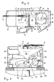
- a door lock 1 for the oven door 45 of an oven 47 comprises 1 and 15, a motor unit 2, a lock unit 3 and a power transmission element 4, which the motor unit 2 with the Lock unit 3 connects.
- the power transmission element 4 is according to An embodiment of a Bowden cable 4.
- the oven 47 is shown in FIG. 1 only a cover plate 5 with a guide plate 5 'and an oven flange 6 indicated, on which the lock unit 3 is attached.
- the motor unit 2 is arranged on the cover plate 5 behind the guide plate 5 ', so that it can be in the area of a directed cooling air flow.
- the motor unit 2 has a motor 8 with a motor switch 9, with a switch 10 for a rod regulator and with switch 11 (microswitch) for the Lock request on.
- the Lock unit 3 no temperature sensitive components. It can therefore in an area of the oven with high ambient temperature be arranged (200 ° to 250 ° CC). In contrast, the motor unit 2 placed in an area where a lower ambient temperature (80 ° to 100 ° C) prevails.
- the microswitch 11 on the motor unit 2 indicates the locked status of the oven and is used for Switching the engine 8.
- a drive slide 13 is mounted in a housing 12 and displaceable by means of the motor 8, which is via a motor transmission 14 a drive pulley 15 with the axis 16 and an eccentric roller 17 drives the drive slide 13.
- the roll 17 engages one Inner surface 18 of the drive slide 13 and thus determines - in Connection with spring forces acting on the drive slide 13 - its movement.
- a rotating with the drive pulley 15 Cam 19 with two diametrically opposed Cam cuts 20 cooperate with the motor switch 9 and causes the motor 8 to be switched off after each 180 ° rotation the drive pulley 15.
- Two support rollers 21 mounted in the housing 12 lie on the circumference of the drive pulley 15 and prevent one Axle 16 loaded by drive slide 13 exerted forces.
- One end of the Bowden cable 4 passes through the housing wall and is in one Hook 22 hooked in the slide 13 in a guide is displaceable longitudinally between two stops 23 and 24.
- a suspension spring 25 supported on the drive slide 13 biases the bracket 22 towards the stop 24, whereby a tensile force is applied to the Bowden cable 4.
- the suspension 22 is with a guide contour 26 for the shift of a switching plunger 27 which is displaceable in the Drive slide 13 is guided and with the microswitch 11 or whose switching pin interacts.
- the guide contour 26 has one middle in the longitudinal direction in the direction of slide movement Control section 28, the switching plunger 27 in the microswitch 11th actuating switch position moves, and two the middle Control section 28 flanking end sections 29 and 30, the each with systems of the suspension 22 on one of the two stops 23, 24 pull the switch plunger 27 back into an off position. So form the parts 22 to 30 an actuator for the Microswitch 11.
- the lock unit 3 has a lock housing 31 which is provided with insert nuts for attachment to the oven flange 6.
- a lock slide 32 is longitudinally displaceable out, whose position on the Bowden cable 4 from the motor unit 2nd is determined.
- the lock slide 32 is by a Lock housing 31 supporting slide compression spring 33 biased - in Fig. 3 to the left - and has a contoured profile edge 34 on the a pivotable about a swing axis 35 and by means of a Rocker spring 36 biased counterclockwise Swing arm 37 abuts with a swing arm roller 38 mounted on it.
- Bolt 39 in the form of a rotating bolt with a hook-shaped Bolt end 40 is pivotable about a bolt axis 41 on the Swing arm 37 mounted and by means of a torsion spring 42 in counterclockwise in contact with a slide projection 43 biased.
- the motor unit 2 and the lock unit 3 are located in FIG. 2 or 3 in the starting position or in the unlocked open position.
- the Sliders 13 and 32 of the two units 2 and 3 are located in the right end position.
- the switching plunger 27 of the motor unit 2 takes a raised position, so that the microswitch 11 is turned off is.
- the movements of the various elements are indicated by arrows.
- For the slider 13 and 32 as well as for the relative movement between the attachment 22 and the drive slide 13 as well as for the seal 44 between the Oven door 45 and the oven flange 6 (Fig. 3) are O-lines drawn in to illustrate the relocations that occur. she are given in Figures 8 and 10 in mm values.
- the bolt 39 designed as a rotary bolt
- the rocker 37 wants to under the action of the rocker spring 36 about the rocker axis 35 rotate and over the rocker roller 38 pressing on the profile edge 34 move the lock slide 32 to the left.
- the torsion spring 42 wants the Swing out the bolt 39 and the hook-shaped bolt end 40 against move the door hook 7.
- the motor unit 2 via the suspension 22 and the drive slide 13, the holding force for the open position of the Lock unit 3 added.
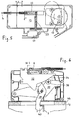
- the drive pulley 15 moves by 180 ° clockwise in the locked closed position (Fig. 9 and 10), wherein the two slides 13 and 32 are in their left end position shift and the switching plunger 27 turns on the microswitch 11 to signal their locking status. They did like indicated the drive slide 13 by 28 mm and the lock slide 32 shifted to the left by 23 mm, while the hook 22 has shifted 5 mm to the right relative to the drive slide 13.
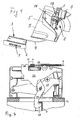
- FIGS. 4 and 8 illustrates. 4 has after a shift of the Lock slide 32 by 10 mm that abuts the slide projection 43 Bolt 39 rotated by about 90 ° so that its hook-shaped bolt end 40 rests on the door hook 7 and engages behind it.
- microswitch 11 is now operated as shown in FIG. 9 illustrated, and thus the locking state is signaled.
- the opening of the door 45 takes place in the reverse order, first the microswitch 11 is switched and then the door is relieved, whereby the bolt 39 moves out of the door hook 7 and finally moves into the Lock unit 3 turns back.
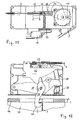
- Fig. 11 illustrates the case that there is a rope break at Bowden cable 4 is coming. Then the suspension spring 25 relaxes further and shifts the hook 22 to the right up to the stop 24, so that the switching plunger 27 in the left end portion 29 of the Guiding contour 26 occurs and the microswitch 11 is switched off, so that there is now no signal for the correct locking. This is useful for safety reasons, so that the rope break at locked door 45 does not lead to an unlocking process in the Lock unit 3 leads.
- Fig. 12 shows that the door 45 despite the existing lock by 7 mm can be wound against the force of the rocker spring 36. This The gap opening enables an emergency release to be made if necessary of a tool. It is important that with this opening of the door 45 slide pressure spring 33 acting on the lock slide 32 prevents slider displacement and thereby conditional impermissible switching operations in the motor unit 2 comes.
- FIGS. 13 and 14 illustrate the relationships that arise in one Locking process with door 45 not closed. Does the Latch 39 does not pivot on the door hook 7 when swiveling out, so swivels the bolt 39 through the guide surface 46 back into the lock housing 31 back. This prevents the protruding bolt end 40 and thus the lock unit 3 by a subsequent slamming of the door 45 can be damaged. Without the door 45 acts on the lock slide 32 continue the force of the rocker 37 with the swing spring 36 so that it in the motor unit 2 does not lead to a relative movement between the Drive slide 13 and the suspension 22 comes. Accordingly the microswitch 11 continues to signal the open position, so that it there is no prerequisite for the start of pyrolysis operation.
- the microswitch 11 is only activated or switched on if there is no error with regard to the lock is present. Even one after the one Interlocking errors are signaled without releasing them comes that only triggered by an intended measure becomes. Therefore, the locked state is secure via the microswitch detected. In addition, it serves to ensure that when locking the Door is actively closed and that when the door is unlocked, none Project lock components
- the invention has been applied to pyrolysis cleaning described an oven.
- the locking is also advantageous regardless of one Pyrolysis cleaning can be used to secure locking to ensure and security against unwanted door opening too ensure, for example also in the sense of child safety.
- the scope is not limited to either Ovens, rather other ovens are also considered given a potential hazard due to excessive heating is.
- An emergency release is for example in the event of a power failure possible at any time because the furnace door is a few millimeters against the force of the movable parts loaded by springs can be opened.
- the oven door can be moved manually into that shown in FIG. 4 Show position, whereupon the bolt 39, for example with a Sheet metal part can be pivoted into the unlocking position.
- the motor 8 used does not require a rotation lock since it is in can approach in both directions.
- the bolt 39 which has a door hook 7, has two arms and is attached in this way the swing arm 37 articulated that he with the free arm 39 ' Slider 32 acted upon.
- the bolt 39 has one Control curve 39 "on that provided with the profile edge 34 Control cam 34 on the lock slide 32 at least temporarily interacts.
- the door lock 1 is in relation to the spring forces in the Motor unit 2 and the lock unit 3 arranged springs such designed that the oven door automatically in the event of a rope break as well is mechanically lockable. In addition, the pyrolysis operation does not start or is stopped immediately.
Landscapes
- Engineering & Computer Science (AREA)
- Chemical & Material Sciences (AREA)
- Combustion & Propulsion (AREA)
- Mechanical Engineering (AREA)
- General Engineering & Computer Science (AREA)
- Physics & Mathematics (AREA)
- Electromagnetism (AREA)
- Electric Ovens (AREA)
- Furnace Housings, Linings, Walls, And Ceilings (AREA)
Applications Claiming Priority (2)
| Application Number | Priority Date | Filing Date | Title |
|---|---|---|---|
| DE2002151726 DE10251726A1 (de) | 2002-11-05 | 2002-11-05 | Türverriegelung für einen Ofen, insbesondere einen Backofen mit pyrolytischer Selbstreinigung |
| DE10251726 | 2002-11-05 |
Publications (3)
| Publication Number | Publication Date |
|---|---|
| EP1418385A2 true EP1418385A2 (fr) | 2004-05-12 |
| EP1418385A3 EP1418385A3 (fr) | 2005-04-20 |
| EP1418385B1 EP1418385B1 (fr) | 2009-12-09 |
Family
ID=32103379
Family Applications (1)
| Application Number | Title | Priority Date | Filing Date |
|---|---|---|---|
| EP20030024822 Expired - Lifetime EP1418385B1 (fr) | 2002-11-05 | 2003-10-31 | Dispositif de verrouillage de porte pour four de cuisson |
Country Status (2)
| Country | Link |
|---|---|
| EP (1) | EP1418385B1 (fr) |
| DE (2) | DE10251726A1 (fr) |
Cited By (5)
| Publication number | Priority date | Publication date | Assignee | Title |
|---|---|---|---|---|
| EP2175200A1 (fr) * | 2008-10-10 | 2010-04-14 | Elettrotecnica Rold Srl | Dispositif de fermeture de porte en particulier d'un four à pyrolyse |
| CN114918896A (zh) * | 2022-06-02 | 2022-08-19 | 东莞市冠佳电子设备有限公司 | 一种基于电轨供电机械手 |
| USD1055618S1 (en) | 2023-06-07 | 2024-12-31 | Sharkninja Operating Llc | Steam air fryer |
| US12458168B2 (en) | 2022-01-13 | 2025-11-04 | Sharkninja Operating Llc | Single opening vent for steam air fryer |
| US12590706B2 (en) | 2023-02-24 | 2026-03-31 | Sharkninja Operating Llc | Cooking device drainage systems |
Citations (1)
| Publication number | Priority date | Publication date | Assignee | Title |
|---|---|---|---|---|
| US4927996A (en) | 1988-05-23 | 1990-05-22 | Robertshaw Controls Company | Cooking apparatus, door latching construction therefor and methods of making the same |
Family Cites Families (3)
| Publication number | Priority date | Publication date | Assignee | Title |
|---|---|---|---|---|
| US5419305A (en) * | 1993-09-02 | 1995-05-30 | Hanley; Roger T. | Automatic bimetal safety latch for self-cleaning oven doors |
| US5477030A (en) * | 1994-04-18 | 1995-12-19 | Robertshaw Controls Company | Cooking apparatus, latching construction therefor and methods of making the same |
| DE19504574C2 (de) * | 1995-02-11 | 2002-05-02 | Miele & Cie | Backofen mit einer Türverriegelungseinrichtung bei Mikrowellenbetrieb |
-
2002
- 2002-11-05 DE DE2002151726 patent/DE10251726A1/de not_active Ceased
-
2003
- 2003-10-31 EP EP20030024822 patent/EP1418385B1/fr not_active Expired - Lifetime
- 2003-10-31 DE DE50312199T patent/DE50312199D1/de not_active Expired - Lifetime
Patent Citations (1)
| Publication number | Priority date | Publication date | Assignee | Title |
|---|---|---|---|---|
| US4927996A (en) | 1988-05-23 | 1990-05-22 | Robertshaw Controls Company | Cooking apparatus, door latching construction therefor and methods of making the same |
Cited By (6)
| Publication number | Priority date | Publication date | Assignee | Title |
|---|---|---|---|---|
| EP2175200A1 (fr) * | 2008-10-10 | 2010-04-14 | Elettrotecnica Rold Srl | Dispositif de fermeture de porte en particulier d'un four à pyrolyse |
| US12458168B2 (en) | 2022-01-13 | 2025-11-04 | Sharkninja Operating Llc | Single opening vent for steam air fryer |
| CN114918896A (zh) * | 2022-06-02 | 2022-08-19 | 东莞市冠佳电子设备有限公司 | 一种基于电轨供电机械手 |
| US12590706B2 (en) | 2023-02-24 | 2026-03-31 | Sharkninja Operating Llc | Cooking device drainage systems |
| USD1055618S1 (en) | 2023-06-07 | 2024-12-31 | Sharkninja Operating Llc | Steam air fryer |
| USD1090151S1 (en) | 2023-06-07 | 2025-08-26 | Sharkninja Operating Llc | Steam air fryer |
Also Published As
| Publication number | Publication date |
|---|---|
| EP1418385B1 (fr) | 2009-12-09 |
| EP1418385A3 (fr) | 2005-04-20 |
| DE10251726A1 (de) | 2004-05-19 |
| DE50312199D1 (de) | 2010-01-21 |
Similar Documents
| Publication | Publication Date | Title |
|---|---|---|
| DE69701026T2 (de) | Vorrichtung zum Öffnen und Schliessen von Türen oder dergleichen, insbesondere von elektrischen Hausgerätstüren oder dergleichen | |
| EP2148035B1 (fr) | Dispositif d'entraînement pour portes de réfrigérateur | |
| DE69007852T2 (de) | Elektrische Türschliessvorrichtung, insbesondere für Kraftfahrzeuge. | |
| DE4321586C2 (de) | Motorbetriebene Schließvorrichtung | |
| DE4427213C5 (de) | Türschloss für ein Kraftfahrzeug | |
| DE69630795T2 (de) | Kupplungsmechanismus für türschliesssystem | |
| DE69104464T2 (de) | Zylinderschloss. | |
| EP1288026B2 (fr) | Attelage de remorque | |
| DE2934482C2 (de) | Aufhängevorrichtung zum Mitführen und Abwerfen von mit Aufhängebeschlägen versehenen Flugzeuglasten | |
| EP3049598A1 (fr) | Poignée de porte de véhicule automobile | |
| DE69300308T2 (de) | Schwenkbetätigungsvorrichtung einer Trittstufenanordnung für Fahrzeuge. | |
| EP2561164B1 (fr) | Agencement de cylindre de fermeture | |
| DE102013222955A1 (de) | Doppelte Haubenverriegelungsanordnung | |
| DE69408742T2 (de) | Verriegelungssystem für Fahrzeugtüren | |
| DE69408741T2 (de) | Türverriegelungssystem für Fahrzeuge | |
| EP2248966A1 (fr) | Serrure de porte dotée d'un élément de fermeture et entraînement d'élément de fermeture commutable | |
| EP1418385A2 (fr) | Dispositif de verrouillage de porte pour four de cuisson | |
| EP1658410A1 (fr) | Serrure de portiere de vehicule automobile | |
| DE102013214221B3 (de) | Vorrichtung und Verfahren zur Blockierung einer Schnellverstellung einer Gewindespindel | |
| DE19717640B4 (de) | Türschließvorrichtung | |
| EP3665349A1 (fr) | Serrure de porte | |
| EP2025853B1 (fr) | Dispositif d'entraîneur pour un dispositif d'entraînement de porte, un tel dispositif d'entraînement de porte et une porte | |
| DE19916191A1 (de) | Vorrichtung zur Verriegelung einer Haube eines Kraftfahrzeuges | |
| EP1683936B1 (fr) | Serrure avec pêne demi-tour et entraînement pour le pêne demi-tour | |
| DE102021104519B4 (de) | Vorrichtung zum Öffnen und Verschließen einer Zugriffsöffnung in einer Fahrzeugkarosserie |
Legal Events
| Date | Code | Title | Description |
|---|---|---|---|
| PUAI | Public reference made under article 153(3) epc to a published international application that has entered the european phase |
Free format text: ORIGINAL CODE: 0009012 |
|
| AK | Designated contracting states |
Kind code of ref document: A2 Designated state(s): AT BE BG CH CY CZ DE DK EE ES FI FR GB GR HU IE IT LI LU MC NL PT RO SE SI SK TR |
|
| AX | Request for extension of the european patent |
Extension state: AL LT LV MK |
|
| PUAL | Search report despatched |
Free format text: ORIGINAL CODE: 0009013 |
|
| AK | Designated contracting states |
Kind code of ref document: A3 Designated state(s): AT BE BG CH CY CZ DE DK EE ES FI FR GB GR HU IE IT LI LU MC NL PT RO SE SI SK TR |
|
| AX | Request for extension of the european patent |
Extension state: AL LT LV MK |
|
| 17P | Request for examination filed |
Effective date: 20051020 |
|
| AKX | Designation fees paid |
Designated state(s): DE FR IT |
|
| 17Q | First examination report despatched |
Effective date: 20060901 |
|
| GRAP | Despatch of communication of intention to grant a patent |
Free format text: ORIGINAL CODE: EPIDOSNIGR1 |
|
| GRAS | Grant fee paid |
Free format text: ORIGINAL CODE: EPIDOSNIGR3 |
|
| GRAA | (expected) grant |
Free format text: ORIGINAL CODE: 0009210 |
|
| AK | Designated contracting states |
Kind code of ref document: B1 Designated state(s): DE FR IT |
|
| REF | Corresponds to: |
Ref document number: 50312199 Country of ref document: DE Date of ref document: 20100121 Kind code of ref document: P |
|
| PLBE | No opposition filed within time limit |
Free format text: ORIGINAL CODE: 0009261 |
|
| STAA | Information on the status of an ep patent application or granted ep patent |
Free format text: STATUS: NO OPPOSITION FILED WITHIN TIME LIMIT |
|
| 26N | No opposition filed |
Effective date: 20100910 |
|
| PG25 | Lapsed in a contracting state [announced via postgrant information from national office to epo] |
Ref country code: IT Free format text: LAPSE BECAUSE OF NON-PAYMENT OF DUE FEES Effective date: 20101031 |
|
| REG | Reference to a national code |
Ref country code: FR Ref legal event code: PLFP Year of fee payment: 13 |
|
| REG | Reference to a national code |
Ref country code: FR Ref legal event code: PLFP Year of fee payment: 14 |
|
| REG | Reference to a national code |
Ref country code: FR Ref legal event code: PLFP Year of fee payment: 15 |
|
| PGFP | Annual fee paid to national office [announced via postgrant information from national office to epo] |
Ref country code: DE Payment date: 20171024 Year of fee payment: 15 Ref country code: FR Payment date: 20171023 Year of fee payment: 15 |
|
| REG | Reference to a national code |
Ref country code: DE Ref legal event code: R119 Ref document number: 50312199 Country of ref document: DE |
|
| PG25 | Lapsed in a contracting state [announced via postgrant information from national office to epo] |
Ref country code: DE Free format text: LAPSE BECAUSE OF NON-PAYMENT OF DUE FEES Effective date: 20190501 |
|
| PG25 | Lapsed in a contracting state [announced via postgrant information from national office to epo] |
Ref country code: FR Free format text: LAPSE BECAUSE OF NON-PAYMENT OF DUE FEES Effective date: 20181031 |