EP1420192A2 - Dispositif tendeur pour une transmission à organe flexible sans fin d'un appareil auxiliaire - Google Patents
Dispositif tendeur pour une transmission à organe flexible sans fin d'un appareil auxiliaire Download PDFInfo
- Publication number
- EP1420192A2 EP1420192A2 EP03022993A EP03022993A EP1420192A2 EP 1420192 A2 EP1420192 A2 EP 1420192A2 EP 03022993 A EP03022993 A EP 03022993A EP 03022993 A EP03022993 A EP 03022993A EP 1420192 A2 EP1420192 A2 EP 1420192A2
- Authority
- EP
- European Patent Office
- Prior art keywords
- torsion spring
- tensioning
- spring
- clamping
- arm
- Prior art date
- Legal status (The legal status is an assumption and is not a legal conclusion. Google has not performed a legal analysis and makes no representation as to the accuracy of the status listed.)
- Granted
Links
Images


Classifications
-
- F—MECHANICAL ENGINEERING; LIGHTING; HEATING; WEAPONS; BLASTING
- F16—ENGINEERING ELEMENTS AND UNITS; GENERAL MEASURES FOR PRODUCING AND MAINTAINING EFFECTIVE FUNCTIONING OF MACHINES OR INSTALLATIONS; THERMAL INSULATION IN GENERAL
- F16H—GEARING
- F16H7/00—Gearings for conveying rotary motion by endless flexible members
- F16H7/08—Means for varying tension of belts, ropes or chains
- F16H7/10—Means for varying tension of belts, ropes or chains by adjusting the axis of a pulley
- F16H7/12—Means for varying tension of belts, ropes or chains by adjusting the axis of a pulley of an idle pulley
- F16H7/1254—Means for varying tension of belts, ropes or chains by adjusting the axis of a pulley of an idle pulley without vibration damping means
- F16H7/1281—Means for varying tension of belts, ropes or chains by adjusting the axis of a pulley of an idle pulley without vibration damping means where the axis of the pulley moves along a substantially circular path
-
- F—MECHANICAL ENGINEERING; LIGHTING; HEATING; WEAPONS; BLASTING
- F16—ENGINEERING ELEMENTS AND UNITS; GENERAL MEASURES FOR PRODUCING AND MAINTAINING EFFECTIVE FUNCTIONING OF MACHINES OR INSTALLATIONS; THERMAL INSULATION IN GENERAL
- F16H—GEARING
- F16H7/00—Gearings for conveying rotary motion by endless flexible members
- F16H7/08—Means for varying tension of belts, ropes or chains
- F16H7/10—Means for varying tension of belts, ropes or chains by adjusting the axis of a pulley
- F16H7/12—Means for varying tension of belts, ropes or chains by adjusting the axis of a pulley of an idle pulley
- F16H7/1209—Means for varying tension of belts, ropes or chains by adjusting the axis of a pulley of an idle pulley with vibration damping means
- F16H7/1218—Means for varying tension of belts, ropes or chains by adjusting the axis of a pulley of an idle pulley with vibration damping means of the dry friction type
-
- F—MECHANICAL ENGINEERING; LIGHTING; HEATING; WEAPONS; BLASTING
- F16—ENGINEERING ELEMENTS AND UNITS; GENERAL MEASURES FOR PRODUCING AND MAINTAINING EFFECTIVE FUNCTIONING OF MACHINES OR INSTALLATIONS; THERMAL INSULATION IN GENERAL
- F16H—GEARING
- F16H7/00—Gearings for conveying rotary motion by endless flexible members
- F16H7/08—Means for varying tension of belts, ropes or chains
- F16H2007/0802—Actuators for final output members
- F16H2007/081—Torsion springs
-
- F—MECHANICAL ENGINEERING; LIGHTING; HEATING; WEAPONS; BLASTING
- F16—ENGINEERING ELEMENTS AND UNITS; GENERAL MEASURES FOR PRODUCING AND MAINTAINING EFFECTIVE FUNCTIONING OF MACHINES OR INSTALLATIONS; THERMAL INSULATION IN GENERAL
- F16H—GEARING
- F16H7/00—Gearings for conveying rotary motion by endless flexible members
- F16H7/08—Means for varying tension of belts, ropes or chains
- F16H2007/0802—Actuators for final output members
- F16H2007/0825—Actuators for final output members influenced by other actuators of output members
-
- F—MECHANICAL ENGINEERING; LIGHTING; HEATING; WEAPONS; BLASTING
- F16—ENGINEERING ELEMENTS AND UNITS; GENERAL MEASURES FOR PRODUCING AND MAINTAINING EFFECTIVE FUNCTIONING OF MACHINES OR INSTALLATIONS; THERMAL INSULATION IN GENERAL
- F16H—GEARING
- F16H7/00—Gearings for conveying rotary motion by endless flexible members
- F16H7/08—Means for varying tension of belts, ropes or chains
- F16H2007/0863—Finally actuated members, e.g. constructional details thereof
- F16H2007/0874—Two or more finally actuated members
Definitions
- the invention relates to a tensioning device for an enveloping drive Drive unit, in particular a belt drive of a starter generator Internal combustion engine, which on a housing of the unit arranged clamping device against a common axis of rotation Effect of a spring swiveling tension arms for tension rollers respective system on the alternating train run and empty run of the envelope drive includes.
- a clamping device of the type with the aforementioned generic features is e.g. known from US Pat. No. 4,758,208 for the belt drive of a starter-generator arrangement, wherein the tensioning arms carrying tensioning arms on a to the generator shaft coaxial extension on the front of the starter-generator housing pivotally mounted and by means of an extension circumferentially arranged helical torsion spring or leg spring relative held to each other in a V-shaped, load-dependent variable position are.
- the generator housing is changing under the effect Driving torques are limited in terms of rotational angle relative to the internal combustion engine arranged to control a ratchet that is on the tension arms provided gears interacts such that the Tension arm is fixed with the tension roller acting on the tension strand and only the tension arm with the tension pulley effective on the empty run is pivotable.
- the invention has for its object a generic Show clamping device of less space or installation space.
- the Clamping device arranged on the outer circumference of the unit housing Carrying part includes with a bearing bush oriented parallel to the aggregate shaft, the storage of a rotatably connected to the clamping arms Torsion spring device that is inserted into the bearing bush on the one hand strikes against this or the supporting part and the other hand by means of a Change from train strand to empty strand effective damping device in the Bearing bush is secured rotatably.
- a simple modification of the generator housing by arranging two aligned tabs with openings allows it in the design of Invention on the unit housing a separately designed support part to be provided with a bearing bush arranged on support arms, the one with the Axis of rotation of the clamping arms identical longitudinal axis at the intersection of two Auxiliary straight line lies at a distance from the respective traction strand of the envelope drives half the diameter of the tension pulleys are arranged in parallel.
- the starter generator can be closely adjacent Space can be used advantageously.
- Another advantage is that on the respective traction strand the corresponding tension pulley due to the invention specified clamping arm axis of rotation acts transversely on the respective drive wheel tangentially fed train strand.
- the construction is particularly simple Torsion spring device achieved in that this one with one of the Clamping arms connected non-rotatably and rotatably mounted in the bearing bush Includes tube, which is non-rotatably connected in the end area remote from the tension arm a torsion spring arranged in the tube, which in the other end section with the other clamping arm cooperates in a rotationally fixed manner.
- a simple relative securing of the position of the two clamping arms to each other is further achieved in that the torsion spring connected in a rotationally fixed manner Clamping arm in a fork-like end section of the other clamping arm Game is arranged, the torsion spring with the tube connected tension arm end section with on a free passage of Torsion spring provided openings.
- the torsion spring is a cylindrical torsion bar spring or one made of layered spring plate strip is formed torsion bar, the respective torsion bar spring for damping the tensioning arms carrying tensioning arms with the inner wall of the tube via a rubber-elastic torsion spring is connected to the so-called internal damping of the tensioning device.
- the torsion spring is a coil spring, whose widening turns with torsion stress Inner wall of the pipe frictionally for internal damping interact.
- the tensioning device advantageously enables Way that each tension arm cranked relative to its tension roller is designed that each clamping arm with the torsion spring device in interacts essentially free of bending moments.
- the air conditioning compressor is on a housing 5 of the unit or generator 3 arranged.
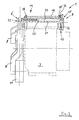
- the clamping device 1 comprises about a common axis of rotation 6 against the action of a spring 7 pivotable clamping arms 8.9 for Tensioners 10,11 for the respective system on the operating mode changing Tension strand 12, 12 'and empty strand 13, 13' of the belt drive 2.
- tensioning device 1 comprises a on the outer circumference of the Generator housing 5 arranged support member 14 with a generator shaft 15 parallel bearing bush 16, the storage of one with the Clamping arms 8.9 torsion spring device 7 is connected in a rotationally fixed manner. This strikes when inserted into the bearing bush 16 on the one hand against this or the support member 14 and on the other hand by means of a change of train strand on empty run and vice versa effective damping device 17 in the Bearing bush 16 held rotatably secured.
- a variant not shown, includes one on the unit housing 5 Integrated eye as a supporting part of a bearing bush, the longitudinal axis of which is also at the intersection "Z" of two, to the respective train strand at a distance of half Tensioner roller diameter of arranged parallels.
- the torsion spring device 7 includes one with the Clamping arm 8 rotatably connected and rotatable in the bearing bush 16 mounted tube 20, which is non-rotatably connected in the end region remote from the clamping arm with a torsion spring 21 arranged in the tube 20. This acts in the other End section with the other clamping arm 9 rotatably together.
- the torsion spring 21 is connected in a rotationally fixed manner Clamping arm 9 in a fork-like end section 8 'of the other clamping arm 8 is arranged with play, which with the torsion spring tube 20 rotatably connected clamping arm end section 8 'with on the free passage of Torsion spring 21 provided openings 22 is provided.
- the torsion spring 21 is a cylindrical one Torsion bar spring or one formed from layered spring leaf strips Torsion bar.
- the respective torsion or Torsion bar spring 21 with the inner wall of the torsion spring tube 20 a rubber-elastic torsion spring 23 connected.
- a helical spring can also be used as the torsion spring 21 Find use whose widening under torsional stress Windings with the inner wall of the tube 20 frictionally for the purpose of inner Interaction work together.
- each tensioning arm 8.9 is cranked relative to its tensioning roller 10.11 is designed such that each tensioning arm 8, 9 with the torsion spring device 7 interacts essentially without bending moments.
Landscapes
- Engineering & Computer Science (AREA)
- General Engineering & Computer Science (AREA)
- Mechanical Engineering (AREA)
- Devices For Conveying Motion By Means Of Endless Flexible Members (AREA)
Applications Claiming Priority (2)
| Application Number | Priority Date | Filing Date | Title |
|---|---|---|---|
| DE2002153450 DE10253450A1 (de) | 2002-11-16 | 2002-11-16 | Spannvorrichtung für einen Hülltrieb eines Aggregates |
| DE10253450 | 2002-11-16 |
Publications (3)
| Publication Number | Publication Date |
|---|---|
| EP1420192A2 true EP1420192A2 (fr) | 2004-05-19 |
| EP1420192A3 EP1420192A3 (fr) | 2006-05-10 |
| EP1420192B1 EP1420192B1 (fr) | 2007-02-14 |
Family
ID=32115549
Family Applications (1)
| Application Number | Title | Priority Date | Filing Date |
|---|---|---|---|
| EP20030022993 Expired - Lifetime EP1420192B1 (fr) | 2002-11-16 | 2003-10-10 | Dispositif tendeur pour une transmission à organe flexible sans fin d'un appareil auxiliaire |
Country Status (3)
| Country | Link |
|---|---|
| EP (1) | EP1420192B1 (fr) |
| DE (2) | DE10253450A1 (fr) |
| ES (1) | ES2280662T3 (fr) |
Cited By (9)
| Publication number | Priority date | Publication date | Assignee | Title |
|---|---|---|---|---|
| WO2004088171A1 (fr) * | 2003-04-02 | 2004-10-14 | Dayco Europe S.R.L. Con Unico Socio | Tensionneur de courroie a deux bras |
| EP1437528A3 (fr) * | 2003-01-10 | 2006-05-10 | Muhr und Bender KG | Tendeur de courroie |
| EP1736688A2 (fr) | 2005-06-24 | 2006-12-27 | Muhr und Bender KG | Tendeur de courroie avec manchon d'amortissement externe |
| EP1736689A3 (fr) * | 2005-06-24 | 2007-09-19 | Muhr und Bender KG | Tendeur de courroie pour la fixation à un agrégat |
| EP2128489A2 (fr) | 2008-05-28 | 2009-12-02 | Muhr und Bender KG | Dispositif de serrage de bride pour application de générateur/démarreur |
| CN104220780A (zh) * | 2012-03-29 | 2014-12-17 | 利滕斯汽车合伙公司 | 张紧器及环形传动装置 |
| CN108361332A (zh) * | 2018-04-20 | 2018-08-03 | 上海贝序汽车科技有限公司 | 一种片弹簧式皮带张紧轮 |
| CN112065940A (zh) * | 2019-06-11 | 2020-12-11 | 舍弗勒技术股份两合公司 | 用于牵引器件传动机构的牵引器件张紧装置 |
| US10865858B2 (en) | 2015-06-01 | 2020-12-15 | Schaeffler Technologies AG & Co.KG | Belt tensioner |
Families Citing this family (9)
| Publication number | Priority date | Publication date | Assignee | Title |
|---|---|---|---|---|
| DE10321801B4 (de) | 2003-01-10 | 2024-08-08 | Muhr Und Bender Kg | Riemenspannvorrichtung |
| DE10337586A1 (de) * | 2003-08-16 | 2005-03-10 | Ina Schaeffler Kg | Spannvorrichtung |
| DE102005039719A1 (de) * | 2005-08-23 | 2007-03-22 | Schaeffler Kg | Spannsystem für einen Zugmitteltrieb mit einem in den Zugmittel integrierten Startergenerator |
| DE102008004481A1 (de) | 2008-01-16 | 2009-07-23 | Bayerische Motoren Werke Aktiengesellschaft | Zugmittelspanneinrichtung |
| DE102008026064B4 (de) | 2008-05-30 | 2012-09-27 | Muhr Und Bender Kg | Riemenspanneranordnung für einen Riementrieb |
| DE102010019613B4 (de) | 2010-05-06 | 2019-02-21 | Litens Automotive Gmbh | Spanner und Endlostriebanordnung |
| DE102012210557A1 (de) * | 2012-06-22 | 2013-12-24 | Bayerische Motoren Werke Aktiengesellschaft | Riemenspannvorrichtung |
| WO2014085917A1 (fr) | 2012-12-07 | 2014-06-12 | Litens Automotive Partnership | Agencement de tendeur et de transmission sans fin |
| EP4006380B1 (fr) | 2016-09-13 | 2024-09-04 | Litens Automotive Partnership | Tendeur en v et agencement d'entraînement sans fin |
Citations (4)
| Publication number | Priority date | Publication date | Assignee | Title |
|---|---|---|---|---|
| US4758208A (en) | 1987-07-13 | 1988-07-19 | General Motors Corporation | Automatic belt tensioner for vehicle combined starter-generator |
| DE4001689C1 (en) | 1990-01-22 | 1991-09-05 | Mercedes-Benz Aktiengesellschaft, 7000 Stuttgart, De | Tensioner for belt drive - has tension roller on lever with spiral torsion spring linked to housing |
| DE4345150A1 (de) | 1993-11-10 | 1995-05-11 | Schaeffler Waelzlager Kg | Riemenspanner mit stufenartiger Dämpfungscharakteristik |
| DE19926615A1 (de) | 1999-06-11 | 2000-12-14 | Schaeffler Waelzlager Ohg | Spanneinrichtung für Zugmittel wie Riemen oder Ketten |
Family Cites Families (6)
| Publication number | Priority date | Publication date | Assignee | Title |
|---|---|---|---|---|
| GB1585624A (en) * | 1977-08-19 | 1981-03-11 | Cancilla P | Chain tensioner for chain drives |
| US4416647A (en) * | 1981-05-26 | 1983-11-22 | Dayco Corporation | Belt tensioner |
| DE4243451A1 (de) * | 1992-12-22 | 1994-06-23 | Schaeffler Waelzlager Kg | Spanneinrichtung für Zugmittel wie Riemen oder Ketten |
| DE19926647A1 (de) * | 1999-06-11 | 2000-12-14 | Schaeffler Waelzlager Ohg | Spanneinrichtung für Riemen |
| DE10109570A1 (de) * | 2001-02-28 | 2002-09-05 | Ina Schaeffler Kg | Einrichtung zum Entkoppeln von Drehungleichförmigkeiten |
| DE10251859A1 (de) * | 2002-11-07 | 2004-05-19 | Ina-Schaeffler Kg | Feder- und Dämpfungsvorrichtung |
-
2002
- 2002-11-16 DE DE2002153450 patent/DE10253450A1/de not_active Withdrawn
-
2003
- 2003-10-10 DE DE50306482T patent/DE50306482D1/de not_active Expired - Lifetime
- 2003-10-10 EP EP20030022993 patent/EP1420192B1/fr not_active Expired - Lifetime
- 2003-10-10 ES ES03022993T patent/ES2280662T3/es not_active Expired - Lifetime
Patent Citations (4)
| Publication number | Priority date | Publication date | Assignee | Title |
|---|---|---|---|---|
| US4758208A (en) | 1987-07-13 | 1988-07-19 | General Motors Corporation | Automatic belt tensioner for vehicle combined starter-generator |
| DE4001689C1 (en) | 1990-01-22 | 1991-09-05 | Mercedes-Benz Aktiengesellschaft, 7000 Stuttgart, De | Tensioner for belt drive - has tension roller on lever with spiral torsion spring linked to housing |
| DE4345150A1 (de) | 1993-11-10 | 1995-05-11 | Schaeffler Waelzlager Kg | Riemenspanner mit stufenartiger Dämpfungscharakteristik |
| DE19926615A1 (de) | 1999-06-11 | 2000-12-14 | Schaeffler Waelzlager Ohg | Spanneinrichtung für Zugmittel wie Riemen oder Ketten |
Cited By (16)
| Publication number | Priority date | Publication date | Assignee | Title |
|---|---|---|---|---|
| EP1437528A3 (fr) * | 2003-01-10 | 2006-05-10 | Muhr und Bender KG | Tendeur de courroie |
| US7367908B2 (en) | 2003-01-10 | 2008-05-06 | Muhr Und Bender Kg | Belt tensioning device |
| WO2004088171A1 (fr) * | 2003-04-02 | 2004-10-14 | Dayco Europe S.R.L. Con Unico Socio | Tensionneur de courroie a deux bras |
| US7468013B2 (en) | 2003-04-02 | 2008-12-23 | Dayco Europe S.R.L. | Two-arm belt tensioner |
| EP1736688A2 (fr) | 2005-06-24 | 2006-12-27 | Muhr und Bender KG | Tendeur de courroie avec manchon d'amortissement externe |
| EP1736689A3 (fr) * | 2005-06-24 | 2007-09-19 | Muhr und Bender KG | Tendeur de courroie pour la fixation à un agrégat |
| US8821328B2 (en) | 2008-05-28 | 2014-09-02 | Muhr Und Bender Kg | Belt tensioning device for being used with a starter generator |
| EP2128489A3 (fr) * | 2008-05-28 | 2010-03-24 | Muhr und Bender KG | Dispositif de serrage de bride pour application de générateur/démarreur |
| EP2128489A2 (fr) | 2008-05-28 | 2009-12-02 | Muhr und Bender KG | Dispositif de serrage de bride pour application de générateur/démarreur |
| US9551402B2 (en) | 2008-05-28 | 2017-01-24 | Muhr Und Bender Kg | Belt tensioning device for being used with a starter generator |
| DE102008025552B4 (de) * | 2008-05-28 | 2020-06-10 | Muhr Und Bender Kg | Riemenspannvorrichtung für Starter-Generator-Anwendung |
| CN104220780A (zh) * | 2012-03-29 | 2014-12-17 | 利滕斯汽车合伙公司 | 张紧器及环形传动装置 |
| US10865858B2 (en) | 2015-06-01 | 2020-12-15 | Schaeffler Technologies AG & Co.KG | Belt tensioner |
| CN108361332A (zh) * | 2018-04-20 | 2018-08-03 | 上海贝序汽车科技有限公司 | 一种片弹簧式皮带张紧轮 |
| CN108361332B (zh) * | 2018-04-20 | 2024-05-07 | 上海贝序汽车科技有限公司 | 一种片弹簧式皮带张紧轮 |
| CN112065940A (zh) * | 2019-06-11 | 2020-12-11 | 舍弗勒技术股份两合公司 | 用于牵引器件传动机构的牵引器件张紧装置 |
Also Published As
| Publication number | Publication date |
|---|---|
| DE10253450A1 (de) | 2004-05-27 |
| ES2280662T3 (es) | 2007-09-16 |
| DE50306482D1 (de) | 2007-03-29 |
| EP1420192B1 (fr) | 2007-02-14 |
| EP1420192A3 (fr) | 2006-05-10 |
Similar Documents
| Publication | Publication Date | Title |
|---|---|---|
| EP1420192B1 (fr) | Dispositif tendeur pour une transmission à organe flexible sans fin d'un appareil auxiliaire | |
| EP2573423B9 (fr) | Tendeur de courroie pour entrainement par courroie et arrangement de machine avec tendeur de courroie | |
| EP1437528B1 (fr) | Tendeur de courroie | |
| DE19926615A1 (de) | Spanneinrichtung für Zugmittel wie Riemen oder Ketten | |
| DE3590411T (de) | Riemenspannvorrichtung und Herstellungsverfahren | |
| EP1753974A1 (fr) | Mecanisme de traction | |
| EP1398232B1 (fr) | Montage du moteur pour des bras de support | |
| EP2385272B1 (fr) | Tendeur et agencement d'entraînement sans fin | |
| DE102008026064B4 (de) | Riemenspanneranordnung für einen Riementrieb | |
| DE102007050204A1 (de) | Spannvorrichtung für einen Zugmitteltrieb | |
| DE10321801B4 (de) | Riemenspannvorrichtung | |
| EP1558859B1 (fr) | Dispositif de suspension et d'amortissement | |
| EP3115242B1 (fr) | Entraînement hybride pour un vehicule automobile | |
| EP1723349A1 (fr) | Entrainement a chaine ou a courroie et element de tension ou de guidage destine a etre integre dans un entrainement a chaine ou a courroie | |
| EP1781913A1 (fr) | Logement a point d'appui d'un organe | |
| DE19630221C1 (de) | Reibradgetriebe für einen Anlasser einer Verbrennungskraftmaschine | |
| DE10312514A1 (de) | Zugmitteltrieb | |
| DE102007020738A1 (de) | Spannvorrichtung für einen Zugmitteltrieb | |
| DE102016103197A1 (de) | Riemengetriebe und lenksystem | |
| EP1420191A2 (fr) | Tendeur pour un courroie de transmission | |
| WO2005080770A2 (fr) | Transmission par elements de traction flexibles de moteur a combustion interne | |
| DE102012223576A1 (de) | Mechanischer Drehfederspanner | |
| DE102004006907A1 (de) | Spannsystem für einen Zugmitteltrieb | |
| DE102005002253A1 (de) | Riemenspanner | |
| EP1420193A2 (fr) | Tendeur d' entraínement par courroie d' accessoires |
Legal Events
| Date | Code | Title | Description |
|---|---|---|---|
| PUAI | Public reference made under article 153(3) epc to a published international application that has entered the european phase |
Free format text: ORIGINAL CODE: 0009012 |
|
| AK | Designated contracting states |
Kind code of ref document: A2 Designated state(s): AT BE BG CH CY CZ DE DK EE ES FI FR GB GR HU IE IT LI LU MC NL PT RO SE SI SK TR |
|
| AX | Request for extension of the european patent |
Extension state: AL LT LV MK |
|
| PUAL | Search report despatched |
Free format text: ORIGINAL CODE: 0009013 |
|
| AK | Designated contracting states |
Kind code of ref document: A3 Designated state(s): AT BE BG CH CY CZ DE DK EE ES FI FR GB GR HU IE IT LI LU MC NL PT RO SE SI SK TR |
|
| AX | Request for extension of the european patent |
Extension state: AL LT LV MK |
|
| 17P | Request for examination filed |
Effective date: 20060524 |
|
| 17Q | First examination report despatched |
Effective date: 20060821 |
|
| GRAP | Despatch of communication of intention to grant a patent |
Free format text: ORIGINAL CODE: EPIDOSNIGR1 |
|
| GRAS | Grant fee paid |
Free format text: ORIGINAL CODE: EPIDOSNIGR3 |
|
| GRAA | (expected) grant |
Free format text: ORIGINAL CODE: 0009210 |
|
| AKX | Designation fees paid |
Designated state(s): DE ES FR GB IT |
|
| AK | Designated contracting states |
Kind code of ref document: B1 Designated state(s): DE ES FR GB IT |
|
| REG | Reference to a national code |
Ref country code: GB Ref legal event code: FG4D Free format text: NOT ENGLISH |
|
| GBT | Gb: translation of ep patent filed (gb section 77(6)(a)/1977) |
Effective date: 20070214 |
|
| REF | Corresponds to: |
Ref document number: 50306482 Country of ref document: DE Date of ref document: 20070329 Kind code of ref document: P |
|
| ET | Fr: translation filed | ||
| REG | Reference to a national code |
Ref country code: ES Ref legal event code: FG2A Ref document number: 2280662 Country of ref document: ES Kind code of ref document: T3 |
|
| PLBE | No opposition filed within time limit |
Free format text: ORIGINAL CODE: 0009261 |
|
| STAA | Information on the status of an ep patent application or granted ep patent |
Free format text: STATUS: NO OPPOSITION FILED WITHIN TIME LIMIT |
|
| 26N | No opposition filed |
Effective date: 20071115 |
|
| REG | Reference to a national code |
Ref country code: FR Ref legal event code: PLFP Year of fee payment: 13 |
|
| REG | Reference to a national code |
Ref country code: FR Ref legal event code: PLFP Year of fee payment: 14 |
|
| REG | Reference to a national code |
Ref country code: FR Ref legal event code: PLFP Year of fee payment: 15 |
|
| REG | Reference to a national code |
Ref country code: FR Ref legal event code: PLFP Year of fee payment: 16 |
|
| PGFP | Annual fee paid to national office [announced via postgrant information from national office to epo] |
Ref country code: FR Payment date: 20221020 Year of fee payment: 20 |
|
| PGFP | Annual fee paid to national office [announced via postgrant information from national office to epo] |
Ref country code: IT Payment date: 20221031 Year of fee payment: 20 Ref country code: GB Payment date: 20221024 Year of fee payment: 20 Ref country code: ES Payment date: 20221118 Year of fee payment: 20 Ref country code: DE Payment date: 20220621 Year of fee payment: 20 |
|
| P01 | Opt-out of the competence of the unified patent court (upc) registered |
Effective date: 20230502 |
|
| REG | Reference to a national code |
Ref country code: DE Ref legal event code: R071 Ref document number: 50306482 Country of ref document: DE |
|
| REG | Reference to a national code |
Ref country code: ES Ref legal event code: FD2A Effective date: 20231027 |
|
| REG | Reference to a national code |
Ref country code: GB Ref legal event code: PE20 Expiry date: 20231009 |
|
| PG25 | Lapsed in a contracting state [announced via postgrant information from national office to epo] |
Ref country code: GB Free format text: LAPSE BECAUSE OF EXPIRATION OF PROTECTION Effective date: 20231009 |
|
| PG25 | Lapsed in a contracting state [announced via postgrant information from national office to epo] |
Ref country code: ES Free format text: LAPSE BECAUSE OF EXPIRATION OF PROTECTION Effective date: 20231011 |
|
| PG25 | Lapsed in a contracting state [announced via postgrant information from national office to epo] |
Ref country code: GB Free format text: LAPSE BECAUSE OF EXPIRATION OF PROTECTION Effective date: 20231009 Ref country code: ES Free format text: LAPSE BECAUSE OF EXPIRATION OF PROTECTION Effective date: 20231011 |