EP1420281A2 - Méthode et dispositif pour l'acquisition optique à vaste profondeur de champ - Google Patents
Méthode et dispositif pour l'acquisition optique à vaste profondeur de champ Download PDFInfo
- Publication number
- EP1420281A2 EP1420281A2 EP03025215A EP03025215A EP1420281A2 EP 1420281 A2 EP1420281 A2 EP 1420281A2 EP 03025215 A EP03025215 A EP 03025215A EP 03025215 A EP03025215 A EP 03025215A EP 1420281 A2 EP1420281 A2 EP 1420281A2
- Authority
- EP
- European Patent Office
- Prior art keywords
- light
- sample
- arrangement
- detection
- phase
- Prior art date
- Legal status (The legal status is an assumption and is not a legal conclusion. Google has not performed a legal analysis and makes no representation as to the accuracy of the status listed.)
- Withdrawn
Links
Images

Classifications
-
- G—PHYSICS
- G02—OPTICS
- G02B—OPTICAL ELEMENTS, SYSTEMS OR APPARATUS
- G02B21/00—Microscopes
- G02B21/0004—Microscopes specially adapted for specific applications
- G02B21/002—Scanning microscopes
- G02B21/0024—Confocal scanning microscopes (CSOMs) or confocal "macroscopes"; Accessories which are not restricted to use with CSOMs, e.g. sample holders
- G02B21/0032—Optical details of illumination, e.g. light-sources, pinholes, beam splitters, slits, fibers
-
- G—PHYSICS
- G01—MEASURING; TESTING
- G01N—INVESTIGATING OR ANALYSING MATERIALS BY DETERMINING THEIR CHEMICAL OR PHYSICAL PROPERTIES
- G01N21/00—Investigating or analysing materials by the use of optical means, i.e. using sub-millimetre waves, infrared, visible or ultraviolet light
- G01N21/62—Systems in which the material investigated is excited whereby it emits light or causes a change in wavelength of the incident light
- G01N21/63—Systems in which the material investigated is excited whereby it emits light or causes a change in wavelength of the incident light optically excited
- G01N21/64—Fluorescence; Phosphorescence
- G01N21/6428—Measuring fluorescence of fluorescent products of reactions or of fluorochrome labelled reactive substances, e.g. measuring quenching effects, using measuring "optrodes"
-
- G—PHYSICS
- G01—MEASURING; TESTING
- G01N—INVESTIGATING OR ANALYSING MATERIALS BY DETERMINING THEIR CHEMICAL OR PHYSICAL PROPERTIES
- G01N21/00—Investigating or analysing materials by the use of optical means, i.e. using sub-millimetre waves, infrared, visible or ultraviolet light
- G01N21/62—Systems in which the material investigated is excited whereby it emits light or causes a change in wavelength of the incident light
- G01N21/63—Systems in which the material investigated is excited whereby it emits light or causes a change in wavelength of the incident light optically excited
- G01N21/64—Fluorescence; Phosphorescence
- G01N21/645—Specially adapted constructive features of fluorimeters
- G01N21/6456—Spatial resolved fluorescence measurements; Imaging
- G01N21/6458—Fluorescence microscopy
-
- G—PHYSICS
- G02—OPTICS
- G02B—OPTICAL ELEMENTS, SYSTEMS OR APPARATUS
- G02B21/00—Microscopes
- G02B21/0004—Microscopes specially adapted for specific applications
- G02B21/002—Scanning microscopes
- G02B21/0024—Confocal scanning microscopes (CSOMs) or confocal "macroscopes"; Accessories which are not restricted to use with CSOMs, e.g. sample holders
- G02B21/0052—Optical details of the image generation
- G02B21/006—Optical details of the image generation focusing arrangements; selection of the plane to be imaged
-
- G—PHYSICS
- G06—COMPUTING OR CALCULATING; COUNTING
- G06T—IMAGE DATA PROCESSING OR GENERATION, IN GENERAL
- G06T5/00—Image enhancement or restoration
- G06T5/50—Image enhancement or restoration using two or more images, e.g. averaging or subtraction
-
- G—PHYSICS
- G06—COMPUTING OR CALCULATING; COUNTING
- G06T—IMAGE DATA PROCESSING OR GENERATION, IN GENERAL
- G06T7/00—Image analysis
- G06T7/97—Determining parameters from multiple pictures
-
- G—PHYSICS
- G01—MEASURING; TESTING
- G01N—INVESTIGATING OR ANALYSING MATERIALS BY DETERMINING THEIR CHEMICAL OR PHYSICAL PROPERTIES
- G01N21/00—Investigating or analysing materials by the use of optical means, i.e. using sub-millimetre waves, infrared, visible or ultraviolet light
- G01N21/62—Systems in which the material investigated is excited whereby it emits light or causes a change in wavelength of the incident light
- G01N21/63—Systems in which the material investigated is excited whereby it emits light or causes a change in wavelength of the incident light optically excited
- G01N21/64—Fluorescence; Phosphorescence
- G01N2021/6417—Spectrofluorimetric devices
-
- G—PHYSICS
- G01—MEASURING; TESTING
- G01N—INVESTIGATING OR ANALYSING MATERIALS BY DETERMINING THEIR CHEMICAL OR PHYSICAL PROPERTIES
- G01N21/00—Investigating or analysing materials by the use of optical means, i.e. using sub-millimetre waves, infrared, visible or ultraviolet light
- G01N21/62—Systems in which the material investigated is excited whereby it emits light or causes a change in wavelength of the incident light
- G01N21/63—Systems in which the material investigated is excited whereby it emits light or causes a change in wavelength of the incident light optically excited
- G01N21/64—Fluorescence; Phosphorescence
- G01N21/645—Specially adapted constructive features of fluorimeters
- G01N2021/6463—Optics
- G01N2021/6478—Special lenses
Definitions
- the invention relates to a method and an arrangement in the Microscopy, especially fluorescence microscopy for examination of predominantly biological samples, preparations and related Components. Also included are those based on fluorescence detection Process for screening active substances (high throughput screening). Simultaneous examinations of fluorescence samples in real time by one simultaneous illumination of the sample in several sample points possible.
- the wavelength of the emitted photon is generally red due to the Stokes shift compared to the excitation radiation, so it has a longer wavelength.
- the Stokes shift enables the fluorescence radiation to be separated from the excitation radiation.
- the fluorescent light is split off from the excitation radiation with suitable dichroic beam splitters in combination with block filters and observed separately. This makes it possible to display individual cell parts stained with different dyes. In principle, however, several parts of a preparation can also be colored simultaneously with different specific dyes (multiple fluorescence).
- Fluorescence signals To distinguish between those emitted by the individual dyes Fluorescence signals, in turn, become special dichroic beam splitters used.
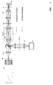
- the depth of modulation of the optical image of an amplitude structure (eg grating) is used as a criterion for the depth of field.
- the image of the periodic structure is characterized by the frequency of the modulation and the phase position (image phase) of the modulation.
- Different projection scenarios can be obtained by a phase shift of the structure perpendicular to the optical axis.
- at least 3 phase images PB at 0 °, 120 ° and 240 ° are generally required.
- I (x, angle) describes the intensity at the respective pixel in the corresponding phase image.
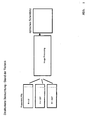
- the measurement sequence for generating an optical sectional image is shown schematically in Fig. 1.
- the 3 or more phase images are recorded sequentially. It is assumed that the sample does not move during the measurement of the images.
- the sectional images or sectional stacks calculated from the phase images can then be displayed on a standard PC and monitor using 3-D evaluation software.
- the spatial resolution along the optical axis depends on the wavelength of the light, the numerical aperture of the lens and the modulation frequency.
- Flow cytometers are used to examine and classify cells and other particles.
- the cells are dissolved in a liquid and are pumped through a capillary.
- a laser beam is focused from the side into the capillary.
- the cells are stained with various dyes or fluorescent biomolecules.
- the excited fluorescent light and the backscattered excitation light are measured.
- the fluorescence signal of the sample is separated from the excitation light by means of dichroic beam splitters (MDB see Fig. 2).
- MDB dichroic beam splitters
- the size of the cells can be determined from the backscattered signal. With the help of the spectral properties of the fluorescence of individual cells, different cells can be separated / sorted or counted separately. The cells are sorted into different capillaries using an electrostatic field. The result, ie for example the number of cells with dye A in comparison to cells with dye B, is often shown in histograms. The flow rate is typically a few 10-100 cm / s. Therefore a highly sensitive detection is needed. To limit the detection volume, confocal detection is carried out according to the prior art. Arrangements for screening dyes, such as in so-called chip readers, are similar in their optical structure to a laser scanning microscope.
- the edge length of the scan fields is some 10 mm.
- These scan fields can be achieved, for example, by increasing the scan angle of the galvo scanner, by arranging the sample in an intermediate image of the microscope arrangement, for example in FIG. 7A, or by a special lens arrangement (macro objective), which magnifies the intermediate image on the sample.
- a disadvantage of the prior art is that several images must be recorded, read out and calculated sequentially. This requires, in particular, higher demands on the setting unit for the different projection scenarios, since otherwise residual modulations (residual structures) remain in the image.
- the speed is reduced by a factor of 3 with which confocal slice images can be generated.
- the usable dynamic range of the detector is restricted depending on the strength of the non-confocal background signal of the sample (ie signals outside the focal plane). With the help of the arrangements according to the invention, it is possible to generate the optical sectional images already at the detector. This prevents the dynamic range of the detector from being restricted by non-confocal background signals. Sequential recording and reading out of the phase images for calculation in the PC is no longer necessary, as a result of which the speed of the detector is fully available for recording confocal sectional images. The formation of residual modulations in the confocal slice is avoided.
- the solution according to the invention is in imaging as well as in analytical Microscopy systems can be used.
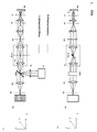
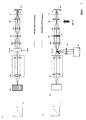
- Fig. 2A side view
- B top view
- Fig. 2A side view
- the solid ones Lines in the beam path represent the lighting beam path dashed the detection beam path.
- the Sample with a line focus e.g. illuminated along the X coordinate that in the coordinate is shifted perpendicular to the line.
- the Light source LQ partial image A
- the Light source LQ which has both one and several wavelengths can emit as well as wavelength bands or a white light source can be in an intermediate image plane ZB of the microscope device by means of an optics ZL is cylindrical lens and RL is transmission lens linear focused.
- Powell Lens as described in US 4,826,299, can be used.
- element produces gaussian Illumination intensity distribution, e.g. typical for single-mode lasers is a more homogeneous intensity distribution along the line.
- the Powell lens and the diffractive or holographic elements become this for example, particularly in a pupil plane of the microscope device advantageously arranged between the light source and scanner.
- the relay optics RL With the relay optics RL the light is imaged into the pupil SC of the microscope arrangement.
- the pupil planes P, SC and MDB of the microscope arrangement result one line focus each along the Y axis.
- the pupil planes SC and the The plane in which the main color divider MDB is located are to each other and to rear focal plane of the lens (P) conjugate pupil planes of the Microscope arrangement so that the scanner is linear and Diffraction-limited focused intensity distribution perpendicular to this can move (y coordinate in the sample).
- the illustration of ZB in the The test is carried out via the scanning optics (SO), the tube lens (TL) and the objective (O).
- the relay optics (RL) generate the conjugate pupil planes MDB and SC of the microscope arrangement.
- the relay optics can be arranged in special arrangements can also be omitted from the prior art. For example, can she at there is no need to shorten the distance between the MDB and SC.
- the transmissive optics ZL for shaping the line can also by a reflective element e.g. Cylinder mirrors to be replaced whose focus is on MDB.
- the cylinder mirror is then (not shown) arranged at 45 ° in the xz plane shown in Fig. 7A. In At this level, the mirror also has its focusing effect. Furthermore, the beam path through the mirror to the light source by 90 ° angled.
- the observation beam path in the direction back to a detector DE (spatial resolution), for example in the case of fluorescence excitation, is shown in dashed lines. Due to the nature of the sample interaction, for example in the case of fluorescence or luminescence excitation, the light emitted by the sample is of low spatial coherence. This means that every point excited in the sample radiates in all spatial directions essentially independently of the neighboring points as point emitters.
- the optics O e.g. a microscope objective
- the light of the sample is focused with the aid of an imaging optics (PO) during confocal detection through a slit diaphragm (SB) (position - slit longitudinal direction in the X direction on the drawing), whereby detection light which has arisen out of focus is suppressed ,
- a slit diaphragm Position - slit longitudinal direction in the X direction on the drawing
- detection light which has arisen out of focus is suppressed
- Behind the slit diaphragm is a line or area detector (DE) (position of the line in the X direction) which is spatially resolved (along the line focus) and which detects the light radiation excited and / or backscattered in the sample.
- the line focus is scanned in one spatial direction with the galvo scanner SC.
- an emission filter in the detection beam path is preferably swung in between PO and SB (dichroic filter) F to suppress the excitation light backscattered by the sample.
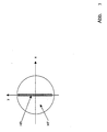
- the components MDB and ZB / G are explained using Figs. 3 and 4.
- the MDB element shown in Fig. 3, which separates the excitation light from the detection light, is located in the pupil MDB.
- the element MDB is shown enlarged.
- MDB is fully mirrored in the gray area HR.
- the area HT drawn in white is highly transmissive, in particular for the wavelength range in which the sample excitation is to take place.
- the outer edge of the MDB represents the pupil diameter of the microscope unit.
- the HR area can be a narrow mirror that is sufficient for reflecting the line.
- the excitation light is focused on the HR area.
- the light reflected directly from the sample in turn reaches the light source in particular in the HR area.
- the excitation light and / or excited light diffusely scattered in the sample hit MDB over its entire surface in accordance with the pupil size of the microscope optics, the portion hitting the HT region being observed in the intermediate image SB / DE.
- the ratio of the areas from HT to HR is:
- the measurement signal S corresponds to half the signal from the optical sectional image, ie the desired information without a background signal, which arises from planes outside the focus.
- Fig. 5 shows the dependence of the measurement signal S (t) on the pixel dwell time t here for a constant location point x. It can be seen that the measurement signal S for pixel dwell times t of more than 10 periods k already corresponds to the signal from the confocal sectional image A / 2.
- the structure can be shifted relative to the sample, for example, by shifting the grating G in the x direction or by moving the scanner SC in the coordinate, which produces a shift along the x coordinate on the sample.
- the grating element G2 can remain in its place or placed in an intermediate image (SB) in front of the detector and so act according to the invention for the light coming from the sample.
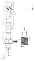
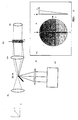
- Fig. 7 shows a further advantageous arrangement for separating the excitation radiation from the detection radiation.
- the spatial separation takes place in an intermediate image ZB / M, whereby the detection radiation or the excitation radiation is tilted with a prismatic element PR (the element is explained in more detail below with reference to FIG. 8).
- the advantage of the arrangement lies in the use of the mostly highly corrected optics RL for the excitation and the detection beam path.
- Fig. 7 shows the grating for structuring in an intermediate image plane ZB / G (see arrow) between tube lens TL and scanner SC. The structure can be pushed relative to the sample by moving the structure or by using a wobble plate.
- the grating G for structuring can also be arranged in an intermediate image plane between the scanners SC and the prismatic element P (not shown). This can be done, for example, by using additional relay optics to generate the additional intermediate image level.
- This has the advantage that the scan line is not scanned over the grid, which can lead to fluctuations in intensity, for example due to irregularities on the grid.
- the structure can then also be pushed relative to the sample by a scanner SC.
- the relay optics RL can also be omitted and the detector DE can be arranged directly in the plane ZB / M, which further simplifies the optical structure.
- Fig. 8 shows the effect of the prismatic element in detail in the yz plane.
- the elements scan optics SO, prismatic element PR / SC scan optics SO1, mirror M in the plane ZB / M for reflecting the excitation light are shown.
- An exemplary embodiment of the element P is shown enlarged in the partial image 8A.) In the xy plane and the yz plane.
- the right representation shows a section through the element PR in an area 1 outside the area 2.
- the element is transmissive, with the areas 1 (area shown in the course) being ground prismatically.
- the area 2 is plane-parallel (the area shown darker).
- the radiation that falls on area 2 is deflected perpendicularly to the scan line (in the y-axis) with respect to the radiation that falls on area 1 (detection radiation) and is additionally spectrally split.
- the differently deflected spectral components of the detection light (from area 1) and the excitation light (from area 2) reach different locations, so that the excitation light and the detection light can be spatially separated.
- the spectral components spatially separated in the intermediate image ZB / M can subsequently be measured spectrally using a detector array which is arranged, for example, in FIG. 7 in the XY plane.
- the detector elements along the Y coordinate measure the spectral information and the elements along the X axis measure the information along the scan line, ie the spatially resolved information.
- the areas 1 and 2 on the prismatic element PR can in principle also be interchanged. This results in a spectral splitting of the excitation radiation, which can be compensated again by means known from the prior art or used to combine spectral components of the light source.
- the transmissive element P can also be replaced by suitable mirror arrangements.
Landscapes
- Physics & Mathematics (AREA)
- General Physics & Mathematics (AREA)
- Health & Medical Sciences (AREA)
- Chemical & Material Sciences (AREA)
- Analytical Chemistry (AREA)
- Engineering & Computer Science (AREA)
- Immunology (AREA)
- Optics & Photonics (AREA)
- General Health & Medical Sciences (AREA)
- Biochemistry (AREA)
- Life Sciences & Earth Sciences (AREA)
- Nuclear Medicine, Radiotherapy & Molecular Imaging (AREA)
- Pathology (AREA)
- Theoretical Computer Science (AREA)
- Chemical Kinetics & Catalysis (AREA)
- Computer Vision & Pattern Recognition (AREA)
- Microscoopes, Condenser (AREA)
- Investigating, Analyzing Materials By Fluorescence Or Luminescence (AREA)
- Length Measuring Devices By Optical Means (AREA)
- Investigating Or Analysing Materials By Optical Means (AREA)
Applications Claiming Priority (2)
| Application Number | Priority Date | Filing Date | Title |
|---|---|---|---|
| DE10254139A DE10254139A1 (de) | 2002-11-15 | 2002-11-15 | Verfahren und Anordnung zur tiefenaufgelösten optischen Erfassung einer Probe |
| DE10254139 | 2002-11-15 |
Publications (2)
| Publication Number | Publication Date |
|---|---|
| EP1420281A2 true EP1420281A2 (fr) | 2004-05-19 |
| EP1420281A3 EP1420281A3 (fr) | 2005-06-01 |
Family
ID=32115578
Family Applications (1)
| Application Number | Title | Priority Date | Filing Date |
|---|---|---|---|
| EP03025215A Withdrawn EP1420281A3 (fr) | 2002-11-15 | 2003-11-05 | Méthode et dispositif pour l'acquisition optique à vaste profondeur de champ |
Country Status (4)
| Country | Link |
|---|---|
| US (1) | US7170696B2 (fr) |
| EP (1) | EP1420281A3 (fr) |
| JP (1) | JP2004170977A (fr) |
| DE (1) | DE10254139A1 (fr) |
Cited By (4)
| Publication number | Priority date | Publication date | Assignee | Title |
|---|---|---|---|---|
| DE102007018048A1 (de) | 2007-04-13 | 2008-10-16 | Michael Schwertner | Verfahren und Anordnung zur optischen Abbildung mit Tiefendiskriminierung |
| WO2009008838A1 (fr) * | 2007-07-06 | 2009-01-15 | National University Of Singapore | Système et procédé de microscopie par modulation focale à fluorescence |
| WO2009043471A1 (fr) * | 2007-09-28 | 2009-04-09 | Carl Zeiss Microimaging Gmbh | Dispositif de détection optique d'un rayonnement lumineux excité et/ou réfléchi dans un échantillon |
| EP1936422A4 (fr) * | 2005-10-13 | 2013-01-16 | Nikon Corp | Microscope |
Families Citing this family (24)
| Publication number | Priority date | Publication date | Assignee | Title |
|---|---|---|---|---|
| US6996264B2 (en) | 2002-10-18 | 2006-02-07 | Leco Corporation | Indentation hardness test system |
| DE10300091A1 (de) * | 2003-01-04 | 2004-07-29 | Lubatschowski, Holger, Dr. | Mikrotom |
| DE10350918B3 (de) * | 2003-10-31 | 2005-04-14 | Evotec Technologies Gmbh | Vorrichtung und Verfahren zur Messung der Transmission eines Objekts |
| DE102004058833A1 (de) * | 2004-12-06 | 2006-06-08 | Leica Microsystems Cms Gmbh | Optische Anordnung für ein Mikroskop und ein Mikroskop |
| US7729750B2 (en) * | 2005-01-20 | 2010-06-01 | The Regents Of The University Of California | Method and apparatus for high resolution spatially modulated fluorescence imaging and tomography |
| DE102005008925A1 (de) * | 2005-02-24 | 2006-09-07 | Leica Microsystems Cms Gmbh | Laser-Mikrodissektionsgerät |
| DE102005046754A1 (de) * | 2005-09-29 | 2007-04-05 | Carl Zeiss Jena Gmbh | Vorrichtung und Verfahren zur tiefenaufgelösten optischen Erfassung einer Probe |
| DE102005046755A1 (de) * | 2005-09-29 | 2007-04-19 | Carl Zeiss Jena Gmbh | Vorrichtung und Verfahren zum Erzeugen eines Bildes eines Objektes |
| JP4844137B2 (ja) * | 2006-01-30 | 2011-12-28 | 株式会社ニコン | 顕微鏡装置 |
| DE102006047912A1 (de) * | 2006-10-06 | 2008-04-10 | Carl Zeiss Microimaging Gmbh | Verfahren und Anordnung zur parallelisierten mikroskopischen Bildgebung |
| WO2008132976A1 (fr) * | 2007-04-12 | 2008-11-06 | Nikon Corporation | Dispositif de microscope |
| DE102007047465A1 (de) * | 2007-09-28 | 2009-04-02 | Carl Zeiss Microimaging Gmbh | Verfahren und Anordnung zur optischen Erfassung einer beleuchteten Probe |
| FR2922658B1 (fr) * | 2007-10-18 | 2011-02-04 | Centre Nat Rech Scient | Systeme d'illuminations structuree d'un echantillon |
| US8280131B2 (en) * | 2007-11-26 | 2012-10-02 | Carl Zeiss Micro Imaging Gmbh | Method and configuration for optically detecting an illuminated specimen |
| DE102008009216A1 (de) * | 2008-02-13 | 2009-08-20 | Carl Zeiss Microimaging Gmbh | Vorrichtung und Verfahren zum räumlich hochauflösenden Abbilden einer Struktur einer Probe |
| FR2941787B1 (fr) | 2009-02-04 | 2011-04-15 | Ecole Polytech | Procede et dispositif d'acquisition de signaux en microscopie laser a balayage. |
| WO2011005239A1 (fr) | 2009-07-08 | 2011-01-13 | Freescale Semiconductor, Inc. | Dispositif de formation d'une image de haute résolution, système d'imagerie et procédé pour déduire une image de haute résolution spatiale |
| CN102883658B (zh) * | 2009-11-19 | 2016-06-22 | 调节成像公司 | 用于使用结构化照明经由单元件检测来分析浑浊介质的方法和设备 |
| DE102010047237B4 (de) | 2010-08-13 | 2021-07-01 | Leica Microsystems Cms Gmbh | Verfahren zum Trennen von Detektionssignalen im Strahlengang einer optischen Einrichtung |
| US8717562B2 (en) * | 2010-08-23 | 2014-05-06 | Scattering Solutions, Inc. | Dynamic and depolarized dynamic light scattering colloid analyzer |
| BR112015010459B1 (pt) | 2012-11-07 | 2021-01-26 | Modulated Imaging, Inc. | método para a medição de uma amostra turva |
| JP6801846B2 (ja) | 2013-02-05 | 2020-12-16 | マサチューセッツ インスティテュート オブ テクノロジー | 3dホログラフィックイメージングフローサイトメトリ |
| DE102014016850B9 (de) * | 2014-11-13 | 2017-07-27 | Carl Zeiss Meditec Ag | Optisches System zur Fluoreszenzbeobachtung |
| KR102243079B1 (ko) * | 2019-06-28 | 2021-04-21 | 주식회사 스몰머신즈 | 광원 위치를 보정하기 위한 현미경 장치 및 그 방법 |
Family Cites Families (21)
| Publication number | Priority date | Publication date | Assignee | Title |
|---|---|---|---|---|
| EP0076866B1 (fr) * | 1981-10-09 | 1985-05-02 | Ibm Deutschland Gmbh | Procédé interpolant de la coupe optique |
| US4826299A (en) | 1987-01-30 | 1989-05-02 | Canadian Patents And Development Limited | Linear deiverging lens |
| US4826269A (en) * | 1987-10-16 | 1989-05-02 | Spectra Diode Laboratories, Inc. | Diode laser arrangement forming bright image |
| GB9014263D0 (en) * | 1990-06-27 | 1990-08-15 | Dixon Arthur E | Apparatus and method for spatially- and spectrally- resolvedmeasurements |
| JPH0445913U (fr) * | 1990-08-23 | 1992-04-20 | ||
| JPH05172741A (ja) * | 1991-12-26 | 1993-07-09 | Hitachi Ltd | 分光型走査顕微鏡 |
| DE4330347C2 (de) * | 1993-09-08 | 1998-04-09 | Leica Lasertechnik | Verwendung einer Vorrichtung zur Selektion und Detektion mindestens zweier Spektralbereiche eines Lichtstrahls |
| US5608529A (en) * | 1994-01-31 | 1997-03-04 | Nikon Corporation | Optical three-dimensional shape measuring apparatus |
| DE19510102C1 (de) * | 1995-03-20 | 1996-10-02 | Rainer Dr Uhl | Konfokales Fluoreszenzmikroskop |
| US5867604A (en) * | 1995-08-03 | 1999-02-02 | Ben-Levy; Meir | Imaging measurement system |
| ATE208911T1 (de) * | 1997-04-04 | 2001-11-15 | Isis Innovation | Abbildungssystem und -verfahren für mikroskopie |
| EP0996854A1 (fr) * | 1997-07-10 | 2000-05-03 | Ruprecht-Karls-Universität Heidelberg | Microscope a champ d'ondes, procedee de microscopie a champ d'ondes servant egalement au sequencage d'adn et procede d'etalonnage utilise en microscopie a champ d'ondes |
| DE19902625A1 (de) * | 1998-01-28 | 1999-09-30 | Leica Microsystems | Vorrichtung zur gleichzeitigen Detektion mehrerer Spektralbereiche eines Lichtstrahls |
| JP2000199855A (ja) * | 1998-11-02 | 2000-07-18 | Olympus Optical Co Ltd | 走査型光学顕微鏡装置 |
| CA2301822A1 (fr) * | 2000-03-24 | 2001-09-24 | 9071 9410 Quebec Inc. | Projection simultanee de plusieurs patrons avec acquisition simultanee pour l'inspection d'objets en trois dimensions |
| DE10017825C2 (de) * | 2000-04-10 | 2003-05-08 | Till I D Gmbh | Polychromatische Fluoreszenz-Meßvorrichtung |
| DE10038528A1 (de) * | 2000-08-08 | 2002-02-21 | Zeiss Carl Jena Gmbh | Verfahren und Anordnung zur Erhöhung der spektralen und räumlichen Detektorauflösung |
| DE10038527A1 (de) * | 2000-08-08 | 2002-02-21 | Zeiss Carl Jena Gmbh | Anordnung zur Erhöhung der Tiefendiskriminierung optisch abbildender Systeme |
| DE50214827D1 (de) * | 2001-04-07 | 2011-02-10 | Zeiss Carl Microimaging Gmbh | Verfahren und Anordnung zur tiefenaufgelösten optischen Erfassung einer Probe |
| JP3519698B2 (ja) * | 2001-04-20 | 2004-04-19 | 照明 與語 | 3次元形状測定方法 |
| DE10120425C2 (de) * | 2001-04-26 | 2003-12-18 | Leica Microsystems | Scanmikroskop |
-
2002
- 2002-11-15 DE DE10254139A patent/DE10254139A1/de not_active Withdrawn
-
2003
- 2003-04-29 US US10/425,302 patent/US7170696B2/en not_active Expired - Fee Related
- 2003-11-05 EP EP03025215A patent/EP1420281A3/fr not_active Withdrawn
- 2003-11-14 JP JP2003385661A patent/JP2004170977A/ja active Pending
Cited By (5)
| Publication number | Priority date | Publication date | Assignee | Title |
|---|---|---|---|---|
| EP1936422A4 (fr) * | 2005-10-13 | 2013-01-16 | Nikon Corp | Microscope |
| DE102007018048A1 (de) | 2007-04-13 | 2008-10-16 | Michael Schwertner | Verfahren und Anordnung zur optischen Abbildung mit Tiefendiskriminierung |
| US7977625B2 (en) | 2007-04-13 | 2011-07-12 | Michael Schwertner | Method and assembly for optical reproduction with depth discrimination |
| WO2009008838A1 (fr) * | 2007-07-06 | 2009-01-15 | National University Of Singapore | Système et procédé de microscopie par modulation focale à fluorescence |
| WO2009043471A1 (fr) * | 2007-09-28 | 2009-04-09 | Carl Zeiss Microimaging Gmbh | Dispositif de détection optique d'un rayonnement lumineux excité et/ou réfléchi dans un échantillon |
Also Published As
| Publication number | Publication date |
|---|---|
| JP2004170977A (ja) | 2004-06-17 |
| US20040095576A1 (en) | 2004-05-20 |
| US7170696B2 (en) | 2007-01-30 |
| EP1420281A3 (fr) | 2005-06-01 |
| DE10254139A1 (de) | 2004-05-27 |
Similar Documents
| Publication | Publication Date | Title |
|---|---|---|
| DE10257237B4 (de) | Anordnung zur optischen Erfassung von in einer Probe angeregter und/oder rückgestreuter Lichtstrahlung | |
| EP1420281A2 (fr) | Méthode et dispositif pour l'acquisition optique à vaste profondeur de champ | |
| EP1396739B1 (fr) | Méthode et arrangement pour la modulation ajustable de la constitution spectrale et/ou de l'intensité de lumière de l'éclairage et/ou de lumière sonde | |
| EP1248132B1 (fr) | Méthode et dispositif de détection optique à résolution de la profondeur d'un échantillon | |
| DE10004191B4 (de) | Fluoreszenz-Scanmikroskop | |
| EP1504300B1 (fr) | Procede et systeme pour analyser des echantillons | |
| EP2097781B1 (fr) | Microscope laser a diviseur spatial de faisceau | |
| DE10151217B4 (de) | Verfahren zum Betrieb eines Laser-Scanning-Mikroskops | |
| EP1496386A2 (fr) | Système pour la détection de la radiation émise ou rétrodiffusée par un échantillon comprenant deux objectifs | |
| EP1302804A2 (fr) | Procédé pour la détermination optique de paramètres caractéristiques d'un échantillon | |
| WO2018234453A1 (fr) | Microscopie à balayage à haute résolution avec distinction d'au moins deux gammes de longueur d'onde | |
| EP1307726A1 (fr) | Procede et dispositif pour determiner le comportement, lie a la longueur d'onde, d'un echantillon eclaire | |
| EP1882970A1 (fr) | Microscope à balayage par laser pour le contrôle de la fluorescence | |
| DE10155002A1 (de) | Verfahren und Anordnung zur tiefenaufgelösten optischen Erfassung einer Probe | |
| EP1720052A1 (fr) | Dispositif destiné à la commande de la radiation lumineuse | |
| WO2005043213A1 (fr) | Dispositif et procede de mesure des proprietes optiques d'un objet | |
| DE10056384C2 (de) | Vorrichtung zur Messung der Lebensdauer eines angeregten Zustandes in einer Probe und Verwendung der Vorrichtung | |
| EP1720054A2 (fr) | Procédé et dispositif destinés à la modification réglable de la lumière | |
| DE102013022026A1 (de) | Mehrfarben-Scanning-Mikroskop | |
| DE102015116598A1 (de) | Verfahren und Mikroskop zur hochauflösenden Abbildung mittels SIM | |
| EP1523667B1 (fr) | Systeme d'imagerie en fond noir destine a l'imagerie en fond noir a resolution spatiale d'un echantillon et methode d'examen | |
| DE102012019464A1 (de) | Konfokales Auflicht-Rastermikroskop zur Multifleck-Abtastung | |
| EP3452856A1 (fr) | Microscope et procédé de localisation de molécules fluorescentes dans trois dimensions spatiales | |
| DE102019119147A1 (de) | Mikroskop und verfahren zur mikroskopie | |
| DE102024108046A1 (de) | Superauflösendes Mikroskop mit schneller quasikonfokaler Detektion |
Legal Events
| Date | Code | Title | Description |
|---|---|---|---|
| PUAI | Public reference made under article 153(3) epc to a published international application that has entered the european phase |
Free format text: ORIGINAL CODE: 0009012 |
|
| 17P | Request for examination filed |
Effective date: 20031106 |
|
| AK | Designated contracting states |
Kind code of ref document: A2 Designated state(s): AT BE BG CH CY CZ DE DK EE ES FI FR GB GR HU IE IT LI LU MC NL PT RO SE SI SK TR |
|
| AX | Request for extension of the european patent |
Extension state: AL LT LV MK |
|
| RIC1 | Information provided on ipc code assigned before grant |
Ipc: 7G 06T 7/00 B Ipc: 7G 02B 21/00 A |
|
| PUAL | Search report despatched |
Free format text: ORIGINAL CODE: 0009013 |
|
| AK | Designated contracting states |
Kind code of ref document: A3 Designated state(s): AT BE BG CH CY CZ DE DK EE ES FI FR GB GR HU IE IT LI LU MC NL PT RO SE SI SK TR |
|
| AX | Request for extension of the european patent |
Extension state: AL LT LV MK |
|
| AKX | Designation fees paid |
Designated state(s): AT BE BG CH CY CZ DE DK EE ES FI FR GB GR HU IE IT LI LU MC NL PT RO SE SI SK TR |
|
| RAP1 | Party data changed (applicant data changed or rights of an application transferred) |
Owner name: CARL ZEISS MICROSCOPY GMBH |
|
| STAA | Information on the status of an ep patent application or granted ep patent |
Free format text: STATUS: THE APPLICATION IS DEEMED TO BE WITHDRAWN |
|
| 18D | Application deemed to be withdrawn |
Effective date: 20140603 |