EP1421894A2 - Endoskopkopf - Google Patents
Endoskopkopf Download PDFInfo
- Publication number
- EP1421894A2 EP1421894A2 EP03026488A EP03026488A EP1421894A2 EP 1421894 A2 EP1421894 A2 EP 1421894A2 EP 03026488 A EP03026488 A EP 03026488A EP 03026488 A EP03026488 A EP 03026488A EP 1421894 A2 EP1421894 A2 EP 1421894A2
- Authority
- EP
- European Patent Office
- Prior art keywords
- endoscope head
- endoscope
- mounting
- mounting adapter
- adapter
- Prior art date
- Legal status (The legal status is an assumption and is not a legal conclusion. Google has not performed a legal analysis and makes no representation as to the accuracy of the status listed.)
- Granted
Links
- 230000001681 protective effect Effects 0.000 claims description 20
- 239000000969 carrier Substances 0.000 claims description 7
- 239000000463 material Substances 0.000 claims description 6
- 238000011010 flushing procedure Methods 0.000 description 13
- 230000003287 optical effect Effects 0.000 description 9
- 238000004659 sterilization and disinfection Methods 0.000 description 5
- 230000007704 transition Effects 0.000 description 4
- 238000010926 purge Methods 0.000 description 3
- 238000012549 training Methods 0.000 description 3
- 239000007788 liquid Substances 0.000 description 2
- 238000004519 manufacturing process Methods 0.000 description 2
- 238000000034 method Methods 0.000 description 2
- 238000005192 partition Methods 0.000 description 2
- 230000001954 sterilising effect Effects 0.000 description 2
- 230000001154 acute effect Effects 0.000 description 1
- 230000005540 biological transmission Effects 0.000 description 1
- 238000004140 cleaning Methods 0.000 description 1
- 239000000470 constituent Substances 0.000 description 1
- 238000010276 construction Methods 0.000 description 1
- 201000010099 disease Diseases 0.000 description 1
- 208000037265 diseases, disorders, signs and symptoms Diseases 0.000 description 1
- 239000003814 drug Substances 0.000 description 1
- 238000003780 insertion Methods 0.000 description 1
- 230000037431 insertion Effects 0.000 description 1
- 230000002262 irrigation Effects 0.000 description 1
- 238000003973 irrigation Methods 0.000 description 1
- 244000005700 microbiome Species 0.000 description 1
- 238000012986 modification Methods 0.000 description 1
- 230000004048 modification Effects 0.000 description 1
- 210000000056 organ Anatomy 0.000 description 1
- 244000052769 pathogen Species 0.000 description 1
- 229920001296 polysiloxane Polymers 0.000 description 1
- 239000007787 solid Substances 0.000 description 1
- 238000012546 transfer Methods 0.000 description 1
Images


Classifications
-
- A—HUMAN NECESSITIES
- A61—MEDICAL OR VETERINARY SCIENCE; HYGIENE
- A61B—DIAGNOSIS; SURGERY; IDENTIFICATION
- A61B1/00—Instruments for performing medical examinations of the interior of cavities or tubes of the body by visual or photographical inspection, e.g. endoscopes; Illuminating arrangements therefor
- A61B1/04—Instruments for performing medical examinations of the interior of cavities or tubes of the body by visual or photographical inspection, e.g. endoscopes; Illuminating arrangements therefor combined with photographic or television appliances
- A61B1/05—Instruments for performing medical examinations of the interior of cavities or tubes of the body by visual or photographical inspection, e.g. endoscopes; Illuminating arrangements therefor combined with photographic or television appliances characterised by the image sensor, e.g. camera, being in the distal end portion
- A61B1/051—Details of CCD assembly
-
- A—HUMAN NECESSITIES
- A61—MEDICAL OR VETERINARY SCIENCE; HYGIENE
- A61B—DIAGNOSIS; SURGERY; IDENTIFICATION
- A61B1/00—Instruments for performing medical examinations of the interior of cavities or tubes of the body by visual or photographical inspection, e.g. endoscopes; Illuminating arrangements therefor
- A61B1/00064—Constructional details of the endoscope body
- A61B1/00071—Insertion part of the endoscope body
- A61B1/0008—Insertion part of the endoscope body characterised by distal tip features
- A61B1/00096—Optical elements
-
- A—HUMAN NECESSITIES
- A61—MEDICAL OR VETERINARY SCIENCE; HYGIENE
- A61B—DIAGNOSIS; SURGERY; IDENTIFICATION
- A61B1/00—Instruments for performing medical examinations of the interior of cavities or tubes of the body by visual or photographical inspection, e.g. endoscopes; Illuminating arrangements therefor
- A61B1/00064—Constructional details of the endoscope body
- A61B1/00103—Constructional details of the endoscope body designed for single use
-
- A—HUMAN NECESSITIES
- A61—MEDICAL OR VETERINARY SCIENCE; HYGIENE
- A61B—DIAGNOSIS; SURGERY; IDENTIFICATION
- A61B1/00—Instruments for performing medical examinations of the interior of cavities or tubes of the body by visual or photographical inspection, e.g. endoscopes; Illuminating arrangements therefor
- A61B1/00064—Constructional details of the endoscope body
- A61B1/00105—Constructional details of the endoscope body characterised by modular construction
-
- A—HUMAN NECESSITIES
- A61—MEDICAL OR VETERINARY SCIENCE; HYGIENE
- A61B—DIAGNOSIS; SURGERY; IDENTIFICATION
- A61B1/00—Instruments for performing medical examinations of the interior of cavities or tubes of the body by visual or photographical inspection, e.g. endoscopes; Illuminating arrangements therefor
- A61B1/04—Instruments for performing medical examinations of the interior of cavities or tubes of the body by visual or photographical inspection, e.g. endoscopes; Illuminating arrangements therefor combined with photographic or television appliances
- A61B1/05—Instruments for performing medical examinations of the interior of cavities or tubes of the body by visual or photographical inspection, e.g. endoscopes; Illuminating arrangements therefor combined with photographic or television appliances characterised by the image sensor, e.g. camera, being in the distal end portion
- A61B1/053—Instruments for performing medical examinations of the interior of cavities or tubes of the body by visual or photographical inspection, e.g. endoscopes; Illuminating arrangements therefor combined with photographic or television appliances characterised by the image sensor, e.g. camera, being in the distal end portion being detachable
-
- A—HUMAN NECESSITIES
- A61—MEDICAL OR VETERINARY SCIENCE; HYGIENE
- A61B—DIAGNOSIS; SURGERY; IDENTIFICATION
- A61B1/00—Instruments for performing medical examinations of the interior of cavities or tubes of the body by visual or photographical inspection, e.g. endoscopes; Illuminating arrangements therefor
- A61B1/00112—Connection or coupling means
- A61B1/00121—Connectors, fasteners and adapters, e.g. on the endoscope handle
-
- A—HUMAN NECESSITIES
- A61—MEDICAL OR VETERINARY SCIENCE; HYGIENE
- A61B—DIAGNOSIS; SURGERY; IDENTIFICATION
- A61B1/00—Instruments for performing medical examinations of the interior of cavities or tubes of the body by visual or photographical inspection, e.g. endoscopes; Illuminating arrangements therefor
- A61B1/12—Instruments for performing medical examinations of the interior of cavities or tubes of the body by visual or photographical inspection, e.g. endoscopes; Illuminating arrangements therefor with cooling or rinsing arrangements
- A61B1/121—Instruments for performing medical examinations of the interior of cavities or tubes of the body by visual or photographical inspection, e.g. endoscopes; Illuminating arrangements therefor with cooling or rinsing arrangements provided with means for cleaning post-use
Definitions
- the invention relates to an endoscope head with several Functional units or elements according to the preamble of the claim 1.
- Endoscopes are particularly diagnostic in medicine Viewing (mirroring) body cavities and hollow organs for Commitment.
- Flexible endoscopes are part of the state of the art well known to introduce an operation of Working tools and an endoscope head that is equipped with lighting devices, Image transmission equipment and others Facilities can be equipped.
- endoscopes are therefore provided with endoscope heads, consisting of a number of electrical, optical and hydraulic Functional elements placed on a bracket and then with a body-compatible material such as silicone. This process will executed such that the distal end of the Endoscope shaft, on which the head is mounted, is encapsulated is the transition between the endoscope head and the endoscope shaft seal.
- a disposable endoscope in particular a head for one To create disposable endoscope that is so simple and inexpensive can be made to be disposed of after use can.
- the essence of the invention is therefore that the endoscope head from a number of modular functional units for the recording and / or training correspondingly assigned Functional units is constructed that the endoscope accordingly must have its intended purpose.
- the head it is preferable to attach the head to an endoscope shaft a kind of adapter or mounting adapter is provided, the one Connection between the functional elements of the head and the corresponding lines and channels in the endoscope shaft or enables.
- the modular construction of the head allows the modular individual parts manufactured very inexpensively and the head assembled become. By reducing the manufacturing costs of the head can thus be created an endoscope that works as a disposable endoscope can be used.
- the endoscope essentially consists of a (not shown) flexible endoscope shaft or tube, one central working channel 1, one on one distal end of the endoscope tube attached mounting adapter 2 and an endoscope head 3, which over the mounting adapter 2 is attached to the endoscope tube.
- the invention Endoscope head 3 in turn essentially consists of a number of modular function carriers 19, 22, 23 for recording and / or training correspondingly assigned Functional units 20, 21, 38 that the endoscope head for For example, performing an examination on a human Body cavity needed.
- the endoscope tube is for the invention described herein interesting in that the mounting adapter 2 quasi as Intermediate piece for the inclusion or linking of certain elements of the endoscope tube with the endoscope head is. So the endoscope tube has (not shown) Bend elements to bend its distal end region, via (also not shown) current or light-conducting Cables or lines that the electronic components 20, 21 in Supply endoscope head 3 with power, or through the information can be transmitted and consisting of a double channel 4 from an internal working channel 1 for insertion of working instruments in the cavity to be considered and from an external flushing channel 5 for supplying one to the Endoscope head 3 attached rinsing nozzle 6 with rinsing liquid, which represents another functional unit.
- this Channel arrangement is consisting of two cylindrical channel elements or - pipes 1a, 7 with different outer diameters to understand, the smaller channel element 1a so in the larger Channel element 7 is that their channel walls on one Tangent along the long side, i.e. they are coaxial, but offset arranged to each other.
- the inner channel element 1a the working channel 1 and from the area between The outer 7 and inner channel element 1 a is created in this Case crescent-shaped flushing channel 5.
- the two channel elements 1a, 7 have different longitudinal axes, by the difference in their radii (those in the further course referred to as the axis offset).
- the inner channel element 1a by one by the height of the endoscope head longer than the outside Channel element 7.
- the double channel 4 from a certain Place continued only from working channel 1.
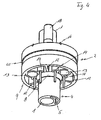
- the mounting adapter 2 essentially consists consisting of two concentric cylinder elements 8, 9 with different radii, which over one to the Adapter plate 10 perpendicular to the cylinder axis with one another are connected on one end of both cylinder elements 8, 9 is preferably formed in one piece with these.
- the outer cylinder element 9 has an outer diameter of essentially corresponds to the outer diameter of the endoscope tube and the inner diameter of the inner cylinder member 8 corresponds essentially to the outer diameter of the double channel 4.
- a circular hole 11 in the adapter plate 10 has one Inner diameter of the outer diameter of the working channel 1 corresponds and its center is with respect to the center of the cylinder elements 8, 9 by the offset of the channel elements added.
- a crescent Overhang which is the support of the mounting adapter 2 on the double channel 4 serves.
- the circular segment-like cavity between the cylinder elements 8, 9 is divided into three sections by radial ribs 12 and there is a cylindrical one in the middle of each section
- Receiving means 13 for receiving the curved elements which extends axially and its wall both with the inner 8 as well as with the outer 9 concentric cylinder element of the adapter 2 is in contact.
- two cylindrical cable guides 14 are arranged, which also extend axially and their wall both with the inner cylinder element 8 and with the receiving means 13 is in contact.
- the mounting adapter 2 has on its mounting plate 10 via a flushing liquid tube 18, which is parallel to and in the area of the working channel 1 without a rinsing channel, when the mounting adapter 2 is plugged onto the endoscope tube via an opening in the adapter plate 10 is connected to the flushing channel 5.
- the Mounting adapter 2 is now simply pushed onto working channel 1 be, the at the transition between the adapter plate 10 and the inner cylinder element 8 crescent-shaped projection a transition between working channel with rinsing channel (double channel) 4 and without flushing channel 1, the cables through the cable guides 14 with the contact points 16 and the curved elements of the endoscope tube connected to the receiving means 13 can be.
- the carrier element 19 has a plate shape which is essentially corresponds to the shape of the mounting plate 10, the axis of the outer edge and the axis of the inner circular hole 25 of the carrier plate 19 are again about the offset of the two channel elements 1, 7 offset from each other. It also has on its outer edge is two notches 24 and an eccentric purge tube hole 26 worked through the support member 19 through which the Flush pipe 18 can be passed through. If the support element 19 rests on the mounting plate 10 and the flushing pipe 18 through the eccentric purge tube hole 26 of the support member 19 is carried out, the notches 24 are in the Carrier plate and the notches 17 in the mounting plate, as well the circular hole 11 of the mounting plate and the circular hole 25 of the Carrier plate each flush with each other.
- the mounting element for the optics 22 essentially consists from a cubic sensor chip chamber 28, an overlying one, through a partition from the sensor or camera chip chamber 28 divided, cylindrical lens chamber 29, one next to the two chambers extending in the axial direction cylindrical Working channel bushing 30 and a parallel extending cylindrical flush pipe bushing 31. Furthermore is a beveled side of the working channel bushing 30 Stiffening rib 32 arranged.
- the superimposed chambers 28, 29, the working channel bushing 30 and the rib 32 are each with respect to a common to the support member 19 standing vertically and bisecting the carrier element 19 Plane symmetrical.
- the flush pipe bushing 31 is outside arranged at this level. As can also be seen from FIG. 3 is, they formed the support member 22 in one piece.
- the holding element 22 has one the shapes of the associated chambers 28, 29 and bushings 30, 31 corresponding outer contour enveloping these shapes. From At a certain height, the outer contour changes into a shape round disc 33, which has a recess 34 at its upper end Has. This creates two superimposed, concentric, round disc sections 35, 36 with the upper disc section 36 slightly tapered upwards. On Section through this recess 34 essentially results in a L-shape, the upright leg of which is slightly inclined so that a slightly acute angle is created between the legs.
- the height of the recess 34 essentially corresponds to the thickness a protective cap 23 described later.
- the sensor chip chamber 28 is open at the bottom and has such dimensions that they receive the sensor chip 21 or surround it can.
- the cylindrical lens chamber is located above 29 arranged and both chambers are through a wall 37 with a center hole separated.
- the lens chamber 29 takes at least one optical lens 38 or a lens system that can be made zoomable and either directly attached to lens holders or in shape a prefabricated cartridge can be inserted into the chamber is.
- the lens chamber 29 is open at the top, it is but preferably with a translucent cover 39 covered.
- the working channel bushing 30 has a certain height an inner diameter that is the outer diameter of the working channel 1 without flushing channel. Located at its end there is a recess 40, the recess depth of the thickness of working channel 1 in the area without a flushing channel.
- the flush pipe bushing 31 has an inner diameter which is in the Essentially corresponds to the outside diameter of the flushing pipe 18 and ends at the upper end of the lens holder member 22 in FIG Nozzle 6 directed towards the cover of the lens chamber 29 is.
- the protective cap 23 has essentially the shape of an inverted one Cup or mug. Their inside diameter corresponds to the outside diameter the support element 19 and its "cup base” 44 has a round opening 42, the diameter of the diameter the upper conical disk 36 of the lens holding member 22 corresponds to halfway up.
- the inner edge of the opening 42 in "Cup base” is rounded and the protective cap 23 is at least partially made of a translucent material overall firmer than the material of the support element 22 for the optics.
- the protective cap 23 has on its inner wall an annular projection 46 is provided.
- the bracket element 22 for the optics is now seated so that the optical sensor chip 21 is covered by the sensor chip chamber 28 and Light from the outside through the lens chamber cover 39, the lens 38 and the hole in the partition 37 through on the optical Sensor chip can fall.
- the inner surface of the Working channel guide 30 flush with the inner surface of the inner Hole 25 in the support member 19 and the inner surface of the purge tube passage 31 is flush with the inner surface of the eccentric Flushing pipe hole 26 in the carrier element 19.
- the luminous element 20 on the carrier plate 19 are attached by the Bracket element 22 is not affected.
- the protective cap or sleeve 23 can be assembled on the Arrangement of support member 19 and lens support member 22 are attached.
- the arrangement comes with the lens holder element 22 introduced into the cup-shaped protective cap 23 in advance the upper, conical disc portion 36 on the Opening 42 is aligned in the "cup base" and the protective inner wall aligned with the circumference of the carrier element 19 becomes.
- the mounting adapter 2 is with the endoscope head 3 connected, the area of the working channel 1 without Rinsing channel protrudes from the mounting adapter 2.
- the assembled one Endoscope head 3 can now be placed on the mounting adapter 2 be by the working channel 1 without flushing channel through the Circular hole 25 of the support element in the working channel bushing 30 is inserted, with the rinsing tube 18 of the adapter 2 through the flushing pipe hole 26 of the carrier plate 19 is inserted into the flushing pipe guide 31 and the clips 41 of the lens support member 22 into the notches 17 of the mounting member 2 are introduced.
- the length of the of the mounting adapter 2 above working channel 1 is selected so that its end in the assembled state at the recess 40 of the working channel bushing 30 is present.
- the projection 46 on the Mounting adapter 2 applied protective sleeve 23 comes with the Return 45 of the mounting adapter 2 engages and thus provides a mechanical connection between the endoscope head 3 and the mounting adapter 2.
- an endoscope can thus be produced, the endoscope head constituent function carrier, i.e. the carrier plate 19, the lens holder member 22 and the protective cover 23, separately can be made by each other, then after their placement with the selected functional units to the endoscope head 3 can be assembled and the endoscope head 3 finally simply via the mounting adapter 2 on the endoscope tube can be attached.
- the endoscope head constituent function carrier i.e. the carrier plate 19, the lens holder member 22 and the protective cover 23, separately can be made by each other, then after their placement with the selected functional units to the endoscope head 3 can be assembled and the endoscope head 3 finally simply via the mounting adapter 2 on the endoscope tube can be attached.
- the lens holding element 22 can also be used only as Cylindrical element attached over the optical sensor 21 be trained without losing the working channel and that Record flush pipe. Rather, in this embodiment the working channel and the irrigation tube parallel to the lens holder element led to the protective cover lying and ending there.
- the mounting element additionally with one to the outside, i.e. over the protective cap protruding tiltable and / or rotatable mirroring and / or Prism device can be equipped with respect to of the chamber 29 receiving the optics is so movable that they choose light rays that are outside the normal range of light the optics in the chamber, redirected to the optics. In this way, the viewing angle the optics to the side or even backwards similar to an adjustable one Optionally extend rear view mirror.
- the invention relates to an endoscope head with a number of functional units such as optics, lighting elements, Rinsing nozzles and the like is equipped.
- the endoscope head consists essentially of a number of modular, plug-in or clickable function carriers 19, 22, 23 for receiving and / or training correspondingly assigned Functional units 20, 21, 38.
Landscapes
- Health & Medical Sciences (AREA)
- Life Sciences & Earth Sciences (AREA)
- Surgery (AREA)
- Biomedical Technology (AREA)
- Medical Informatics (AREA)
- Optics & Photonics (AREA)
- Pathology (AREA)
- Radiology & Medical Imaging (AREA)
- Biophysics (AREA)
- Engineering & Computer Science (AREA)
- Physics & Mathematics (AREA)
- Heart & Thoracic Surgery (AREA)
- Nuclear Medicine, Radiotherapy & Molecular Imaging (AREA)
- Molecular Biology (AREA)
- Animal Behavior & Ethology (AREA)
- General Health & Medical Sciences (AREA)
- Public Health (AREA)
- Veterinary Medicine (AREA)
- Endoscopes (AREA)
- Instruments For Viewing The Inside Of Hollow Bodies (AREA)
- Ultra Sonic Daignosis Equipment (AREA)
Abstract
Description
- Ein Trägerelement 19 zur Aufnahme von elektronischen Bauteilen 20, 21,
- ein eine Optik aufnehmendes/ausbildendes Halterungselement 22 und
- eine Schutzkappe 23 zur Abdeckung der beiden vorstehende Funktionsträger.
Claims (14)
- Endoskopkopf, der mit einer Anzahl von Funktionseinheiten wie beispielsweise Optik, Beleuchtungselemente, Spüldüsen und dergleichen ausgerüstet ist, dadurch gekennzeichnet, dass der Endoskopkopf aus einer Anzahl von modularen Funktionsträgern (19, 22, 23) für das Aufnehmen und/oder Ausbilden entsprechend zugeordneter Funktionseinheiten (20, 21, 38) besteht.
- Endoskopkopf nach Anspruch 1, dadurch gekennzeichnet, dass die Funktionsträger (19, 22, 23) derart ausgestaltet sind, dass die Funktionselemente (20, 21, 38) durch Zusammensetzen der Funktionsträger (19, 22, 23) vorzugsweise selbsttätig korrekt platzierbar und/oder in Funktionsfähigkeit bringbar sind.
- Endoskopkopf gemäß Anspruch 2, dadurch gekennzeichnet, dass die Funktionsträger (19, 22, 23) mit jeweils in vorbestimmten Eingriff miteinander bringbaren, vorzugsweise elastisch deformierbaren Verbindungsabschnitten für eine Schnapp- und/oder Klemmverbindung ausgebildet sind.
- Endoskopkopf gemäß einem der vorstehenden Ansprüche, der aus folgenden Funktionsträgern gebildet ist:einem plattenförmigen Trägerelement (19) zur Aufnahme elektronischer Bauteile (20, 21);einem Halterungselement (22) für eine zumindest eine Linse (38) aufweisende Optik;einer Schutzkappe (23) zum Abdecken des Linsenhalterungselements (22) und der Trägerplatte (19) und vorzugsweise einem Montageadapter (2) zur Befestigung des Endoskopkopfs an einem Endoskopschaft.
- Endoskopkopf gemäss Anspruch 4, dadurch gekennzeichnet, dass der Montageadapter (2) derart ausgebildet ist, um eine Verbindung zwischen im Endoskopschaft ausgebildeten Versorgungskanälen und Leitungen mit den Funktionseinheiten des Endoskopkopfs zu schaffen und/oder zu ermöglichen.
- Endoskopkopf nach Anspruch 5, dadurch gekennzeichnet, dass der Montageadapter (2) mit elektrischen Kontaktstellen (16) ausgebildet ist, and die elektrische Leitungen im Endoskopschaft anschließbar sind.
- Endoskopkopf gemäss Anspruch 6, dadurch gekennzeichnet, dass das Trägerelement (19) an seiner zum Montageadapter (2) zugewandten Seite Kontaktflächen (27) hat, die mit den elektrischen Kontaktstellen (16) des Montageadapters (2) in Kontakt bringbar sind, wenn das Trägerelement (19) mit dem Montageadapter (2) zusammengesetzt wird, wobei auf der zu den Kontaktflächen (27) entgegengesetzten Seite der Trägerplatte (19) die elektronischen Bauteile (20, 21) angeordnet sind, die von den Kontaktstellen (16) über die Kontaktflächen (27) mit elektrischem Strom versorgt werden.
- Endoskopkopf gemäss einem der vorstehenden Ansprüche, dadurch gekennzeichnet, dass
das Halterungselement (22) für die Optik auf der die elektronischen Bauteile tragenden Seite des Trägerelements (19) an diesem befestigt ist und zumindest eine, die Optik aufnehmende Kammer (29) hat, die zu der der Schutzkappe zugewandten Seite des Halterungselements (22) hin offen ist und die sich beim Zusammenbau des Halterungselements (22) mit dem Trägerelement (19) über einem auf dem Trägerelement (19) befindlichen Kamerachip (21) ausrichtet. - Endoskopkopf gemäss einem der vorstehenden Ansprüche, dadurch gekennzeichnet, dass
das Material des Halterungelements (23) weicher und/oder elastischer ist als das Material der Schutzkappe (22). - Endoskopkopf gemäss einem der vorstehenden Ansprüche, gekennzeichnet durch
eine kippbare und/oder drehbare Spiegelungs- und/oder Prismenvorrichtung, die bezüglich der die Optik aufnehmenden Kammer so bewegbar ist, dass sie wahlweise Lichtstrahlen, die außerhalb des normalen Lichteinfallbereichs der in der Kammer befindlichen Optik liegen, auf die Optik umlenkt. - Montageadapter für einen Endoskopkopf vorzugsweise gemäß einem der Ansprüche 1 bis 10, dadurch gekennzeichnet, dass
der Montageadapter (2) so ausgebildet, um zum einen eine mechanische Verbindung zwischen dem Endoskopkopf und einem Enddoskopschaft zu bilden und zum anderen eine Verbindung zwischen in dem Endoskopschaft ausgebildeten Versorgungskanälen und Leitungen mit Funktionseinheiten des Endoskopkopfs zu schaffen und/oder zu ermöglichen. - Montageadapter nach Anspruch 11, dadurch gekennzeichnet, dass
der Montageadapter aus einer äußeren, im wesentlichen zylindrischen Hülse und einer coaxialen inneren, im wesntlichen zylindrischen Hülse besteht, die über profilierte Radialverstrebungen mit der äußeren Hülse vorzugsweise einstückig verbunden ist, wobei die Radialverstrebungen zumindest teilweise die Verbindung der Versorgungskanäle und Leitungen mit den Funktionseinheiten schaffen und/oder ermöglichen. - Montageadapter nach Anspruch 12, gekennzeichnet durch
eine an einer Stirnseite des Adapters ausgebildete Montageplatte (10), auf der der Endoskopkopf montierbar ist, wobei die Montageplatte (10) mechanische und elektrische Anschlüsse für den Endoskopkopf aufweist. - Montageadapter gemäss Anspruch 13, dadurch gekennzeichnet, dass
die elektrischen Anschlüsse als in der Montageplatte (10) ausgebildete flexible Kontaktarme (15) vorgesehen sind, die vorzugsweise über die Fläche der Montageplatte (10) hervorstehende Kontaktstellen (16) haben.
Applications Claiming Priority (2)
| Application Number | Priority Date | Filing Date | Title |
|---|---|---|---|
| DE10254609 | 2002-11-22 | ||
| DE10254609.6A DE10254609B4 (de) | 2002-11-22 | 2002-11-22 | Endoskopkopf |
Publications (4)
| Publication Number | Publication Date |
|---|---|
| EP1421894A2 true EP1421894A2 (de) | 2004-05-26 |
| EP1421894A3 EP1421894A3 (de) | 2004-07-28 |
| EP1421894B1 EP1421894B1 (de) | 2008-01-23 |
| EP1421894B2 EP1421894B2 (de) | 2011-02-23 |
Family
ID=32185907
Family Applications (1)
| Application Number | Title | Priority Date | Filing Date |
|---|---|---|---|
| EP03026488A Expired - Lifetime EP1421894B2 (de) | 2002-11-22 | 2003-11-20 | Endoskopkopf |
Country Status (6)
| Country | Link |
|---|---|
| US (1) | US7371209B2 (de) |
| EP (1) | EP1421894B2 (de) |
| JP (1) | JP2004174242A (de) |
| AT (1) | ATE384471T1 (de) |
| DE (2) | DE10254609B4 (de) |
| ES (1) | ES2302525T3 (de) |
Cited By (2)
| Publication number | Priority date | Publication date | Assignee | Title |
|---|---|---|---|---|
| WO2007124211A3 (en) * | 2006-04-20 | 2008-02-14 | Boston Scient Scimed Inc | Imaging assembly with transparent distal cap |
| EP2594188A1 (de) * | 2011-11-18 | 2013-05-22 | Invendo Medical Gmbh | Medizinisches Endoskop mit einer Kühlvorrichtung |
Families Citing this family (17)
| Publication number | Priority date | Publication date | Assignee | Title |
|---|---|---|---|---|
| AUPS219002A0 (en) * | 2002-05-08 | 2002-06-06 | Lion Eye Institute, The | Digital hand-held imaging device |
| DE102004026005B4 (de) * | 2004-05-27 | 2006-06-14 | Stm Medizintechnik Starnberg Gmbh | ZOOMOBJEKTIV für Endoskopiegeräte |
| US7553278B2 (en) | 2005-06-01 | 2009-06-30 | Cannuflow, Inc. | Protective cap for arthroscopic instruments |
| US8038598B2 (en) * | 2006-05-15 | 2011-10-18 | Baystate Health, Inc. | Balloon endoscope device |
| US8211053B2 (en) * | 2008-05-13 | 2012-07-03 | Equilibrate, Llc | Interosmolar fluid removal |
| US11304590B2 (en) | 2011-02-07 | 2022-04-19 | Endochoice, Inc. | Illuminator circuit board assembly for an endoscope |
| US10517464B2 (en) | 2011-02-07 | 2019-12-31 | Endochoice, Inc. | Multi-element cover for a multi-camera endoscope |
| US20170325665A1 (en) * | 2011-02-07 | 2017-11-16 | Endochoice, Inc. | Illuminator Circuit Board Assembly for An Endoscope |
| EP3150106B1 (de) * | 2011-12-29 | 2024-03-27 | Cook Medical Technologies LLC | Raumoptimierter visualisierungskatheter mit einem kamerazughalter in einem katheter mit dezentriertem lumen |
| DE102013224683A1 (de) * | 2013-12-02 | 2015-06-03 | Digital Endoscopy Gmbh | Endoskopkopf und endoskop |
| WO2020116481A1 (ja) | 2018-12-05 | 2020-06-11 | Hoya株式会社 | 内視鏡、先端部品および内視鏡の製造方法 |
| TWM576855U (zh) * | 2018-12-12 | 2019-04-21 | 榮晶生物科技股份有限公司 | Endoscope device and its cable assembly |
| TWI733074B (zh) * | 2019-01-09 | 2021-07-11 | 榮晶生物科技股份有限公司 | 微型電子裝置及其電路基板 |
| TWI721762B (zh) * | 2020-01-22 | 2021-03-11 | 台灣愛司帝科技股份有限公司 | 全屏幕式影像顯示器及其光學組件 |
| US12268368B2 (en) | 2020-04-30 | 2025-04-08 | Ambu A/S | Medical visualisation device |
| CN116419706A (zh) * | 2020-09-25 | 2023-07-11 | 波士顿科学国际有限公司 | 医学成像装置 |
| DE102023103177A1 (de) * | 2023-02-09 | 2024-08-14 | Karl Storz Se & Co. Kg | Medizinisches Bildgebungsinstrument, Verbinder, System und Verfahren für den Betrieb eines medizinischen Bildgebungsinstruments |
Family Cites Families (24)
| Publication number | Priority date | Publication date | Assignee | Title |
|---|---|---|---|---|
| JPS6066223A (ja) * | 1983-09-21 | 1985-04-16 | Olympus Optical Co Ltd | 撮像装置 |
| JP3107220B2 (ja) * | 1990-11-15 | 2000-11-06 | オリンパス光学工業株式会社 | 内視鏡装置 |
| JP3083353B2 (ja) * | 1991-08-06 | 2000-09-04 | オリンパス光学工業株式会社 | 内視鏡装置 |
| DE4129961C2 (de) * | 1991-09-10 | 1996-02-15 | Wolf Gmbh Richard | Videoendoskop mit Festkörperbildaufnahmevorrichtung |
| JP3270106B2 (ja) * | 1992-04-30 | 2002-04-02 | オリンパス光学工業株式会社 | 内視鏡装置 |
| JPH05344952A (ja) * | 1992-06-16 | 1993-12-27 | Olympus Optical Co Ltd | 内視鏡撮像装置 |
| US5643175A (en) | 1992-09-01 | 1997-07-01 | Adair; Edwin L. | Sterilizable endoscope with separable disposable tube assembly |
| US5438975A (en) * | 1993-03-24 | 1995-08-08 | Machida Endoscope Co., Ltd. | Distal tip of endoscope having spirally coiled control wires |
| US5371384A (en) † | 1993-06-24 | 1994-12-06 | Sony Corporation | Solid state imaging device having a light emitting diode |
| US5447148A (en) * | 1993-07-08 | 1995-09-05 | Vision Sciences, Inc. | Endoscopic contamination protection system to facilitate cleaning of endoscopes |
| US5398670A (en) * | 1993-08-31 | 1995-03-21 | Ethicon, Inc. | Lumen traversing device |
| JPH07327916A (ja) * | 1994-06-02 | 1995-12-19 | Olympus Optical Co Ltd | 視野方向可変型内視鏡 |
| JPH08150113A (ja) * | 1994-11-30 | 1996-06-11 | Toshiba Corp | 内視鏡装置 |
| US6095970A (en) * | 1997-02-19 | 2000-08-01 | Asahi Kogaku Kogyo Kabushiki Kaisha | Endoscope |
| JP3665438B2 (ja) * | 1997-02-19 | 2005-06-29 | ペンタックス株式会社 | 電子内視鏡 |
| JP3665443B2 (ja) * | 1997-02-19 | 2005-06-29 | ペンタックス株式会社 | 内視鏡 |
| JP3758815B2 (ja) † | 1997-06-18 | 2006-03-22 | ペンタックス株式会社 | 内視鏡の先端部 |
| JPH11276433A (ja) * | 1998-03-26 | 1999-10-12 | Olympus Optical Co Ltd | 電子内視鏡 |
| DE19839188C2 (de) † | 1998-08-28 | 2003-08-21 | Storz Endoskop Gmbh Schaffhaus | Endoskop |
| JP3721882B2 (ja) * | 1999-09-14 | 2005-11-30 | フジノン株式会社 | 内視鏡の挿入部 |
| GB9928025D0 (en) * | 1999-11-27 | 2000-01-26 | Vlsi Vision Ltd | Improvements in or relating to image sensor devices and endoscopes incorporationg improved image sensor devices |
| JP3345645B2 (ja) * | 2000-06-20 | 2002-11-18 | 東京大学長 | 体腔内観察装置 |
| AU2002219499A1 (en) | 2001-01-19 | 2002-07-30 | Framtidartaekni Ehf. | Hand-held digital imaging diagnostic and operational instrument with wireless transmission data of image |
| JP2004016410A (ja) * | 2002-06-14 | 2004-01-22 | Fuji Photo Optical Co Ltd | 立体電子内視鏡装置 |
-
2002
- 2002-11-22 DE DE10254609.6A patent/DE10254609B4/de not_active Expired - Lifetime
-
2003
- 2003-11-19 US US10/718,238 patent/US7371209B2/en not_active Expired - Lifetime
- 2003-11-20 JP JP2003391365A patent/JP2004174242A/ja active Pending
- 2003-11-20 EP EP03026488A patent/EP1421894B2/de not_active Expired - Lifetime
- 2003-11-20 AT AT03026488T patent/ATE384471T1/de not_active IP Right Cessation
- 2003-11-20 DE DE50309070T patent/DE50309070D1/de not_active Expired - Lifetime
- 2003-11-20 ES ES03026488T patent/ES2302525T3/es not_active Expired - Lifetime
Cited By (4)
| Publication number | Priority date | Publication date | Assignee | Title |
|---|---|---|---|---|
| WO2007124211A3 (en) * | 2006-04-20 | 2008-02-14 | Boston Scient Scimed Inc | Imaging assembly with transparent distal cap |
| US7955255B2 (en) | 2006-04-20 | 2011-06-07 | Boston Scientific Scimed, Inc. | Imaging assembly with transparent distal cap |
| US8870753B2 (en) | 2006-04-20 | 2014-10-28 | Boston Scientific Scimed, Inc. | Imaging assembly with transparent distal cap |
| EP2594188A1 (de) * | 2011-11-18 | 2013-05-22 | Invendo Medical Gmbh | Medizinisches Endoskop mit einer Kühlvorrichtung |
Also Published As
| Publication number | Publication date |
|---|---|
| EP1421894B1 (de) | 2008-01-23 |
| EP1421894B2 (de) | 2011-02-23 |
| ES2302525T3 (es) | 2008-07-16 |
| ATE384471T1 (de) | 2008-02-15 |
| US20040147807A1 (en) | 2004-07-29 |
| EP1421894A3 (de) | 2004-07-28 |
| DE10254609A1 (de) | 2004-06-03 |
| JP2004174242A (ja) | 2004-06-24 |
| US7371209B2 (en) | 2008-05-13 |
| DE50309070D1 (de) | 2008-03-13 |
| DE10254609B4 (de) | 2017-12-07 |
Similar Documents
| Publication | Publication Date | Title |
|---|---|---|
| EP1421894B1 (de) | Endoskopkopf | |
| DE2915425C2 (de) | Saugsteuervorrichtung für ein Endoskop | |
| DE69419010T2 (de) | ANSCHLUSSVORRICHTUNG ZUM ANSCHLIESSEN EINER SPITZE AN EIN DENTALES HANDSTüCK | |
| DE2948564C2 (de) | Anschlußteil für ein Endoskop | |
| EP0369043B2 (de) | Zahnärztliches Handstück mit Mitteln zum kompatiblen Anschluss an unterschiedlich gestaltete Drehkupplungen | |
| DE19609888B4 (de) | Endoskopsatz | |
| EP0199848B1 (de) | Vorrichtung zum Einführen eines Endoskops oder eines chirurgischen Instruments in Körperhöhlen mit Mitteln zum Zuführen und Absaugen eines Spülmediums | |
| DE69812036T2 (de) | Zahnärztliches Handgerät mit darin enthaltender Lichtquelle | |
| DE3718609A1 (de) | Optische beleuchtungsvorrichtung fuer ein endoskop | |
| EP0125687A1 (de) | Gerät für medizinische visuelle Untersuchungen von Körperhöhlen oder -gängen mit einem Handgriff | |
| CH663533A5 (de) | Zahnsteinentfernungs-handstueck. | |
| DE6929423U (de) | Laryngoskop. | |
| DE3332627C2 (de) | ||
| DE3108574A1 (de) | Anordnung zum desinfizieren von flexiblen endoskopen mittels einer im kreislauf stroemenden desinfektionsfluessigkeit | |
| EP1391182A2 (de) | Funktionshandstück mit einem Lichtabstrahlelement an seinem vorderen Ende | |
| DE19513616A1 (de) | Zahnmedizinisches Handstück mit eingebauter Beleuchtungseinrichtung | |
| DE3702441A1 (de) | Punktionsvorrichtung zum absaugen und spuelen eines follikels | |
| DE3636028A1 (de) | Endoskop | |
| WO2023046708A1 (de) | Dentalmedizinische kanüle für dentalspritze zur abgabe von medien | |
| DE2929562B2 (de) | Medizinisches Instrument | |
| DE3128953C2 (de) | Lippenexpander | |
| DE102014113352A1 (de) | Endoskop und Verfahren zur Montage einer Endoskopoptik eines Endoskops | |
| WO2008098740A1 (de) | Medizinisches, insbesondere dentalmedizinisches,handstück mit zwei voneinander getrennten austrittsöffnungen für medien | |
| DE3706943A1 (de) | Beleuchtungseinrichtung fuer ein zahnaerztliches handinstrument | |
| DE4015468C2 (de) |
Legal Events
| Date | Code | Title | Description |
|---|---|---|---|
| PUAI | Public reference made under article 153(3) epc to a published international application that has entered the european phase |
Free format text: ORIGINAL CODE: 0009012 |
|
| AK | Designated contracting states |
Kind code of ref document: A2 Designated state(s): AT BE BG CH CY CZ DE DK EE ES FI FR GB GR HU IE IT LI LU MC NL PT RO SE SI SK TR |
|
| AX | Request for extension of the european patent |
Extension state: AL LT LV MK |
|
| PUAL | Search report despatched |
Free format text: ORIGINAL CODE: 0009013 |
|
| AK | Designated contracting states |
Kind code of ref document: A3 Designated state(s): AT BE BG CH CY CZ DE DK EE ES FI FR GB GR HU IE IT LI LU MC NL PT RO SE SI SK TR |
|
| AX | Request for extension of the european patent |
Extension state: AL LT LV MK |
|
| 17P | Request for examination filed |
Effective date: 20040914 |
|
| 17Q | First examination report despatched |
Effective date: 20050302 |
|
| AKX | Designation fees paid |
Designated state(s): AT BE BG CH CY CZ DE DK EE ES FI FR GB GR HU IE IT LI LU MC NL PT RO SE SI SK TR |
|
| RAP1 | Party data changed (applicant data changed or rights of an application transferred) |
Owner name: INVENDO MEDICAL GMBH |
|
| GRAP | Despatch of communication of intention to grant a patent |
Free format text: ORIGINAL CODE: EPIDOSNIGR1 |
|
| GRAS | Grant fee paid |
Free format text: ORIGINAL CODE: EPIDOSNIGR3 |
|
| GRAA | (expected) grant |
Free format text: ORIGINAL CODE: 0009210 |
|
| AK | Designated contracting states |
Kind code of ref document: B1 Designated state(s): AT BE BG CH CY CZ DE DK EE ES FI FR GB GR HU IE IT LI LU MC NL PT RO SE SI SK TR |
|
| REG | Reference to a national code |
Ref country code: GB Ref legal event code: FG4D Free format text: NOT ENGLISH |
|
| REG | Reference to a national code |
Ref country code: CH Ref legal event code: EP |
|
| REG | Reference to a national code |
Ref country code: IE Ref legal event code: FG4D Free format text: LANGUAGE OF EP DOCUMENT: GERMAN |
|
| REF | Corresponds to: |
Ref document number: 50309070 Country of ref document: DE Date of ref document: 20080313 Kind code of ref document: P |
|
| REG | Reference to a national code |
Ref country code: CH Ref legal event code: NV Representative=s name: E. BLUM & CO. AG PATENT- UND MARKENANWAELTE VSP |
|
| NLV1 | Nl: lapsed or annulled due to failure to fulfill the requirements of art. 29p and 29m of the patents act | ||
| REG | Reference to a national code |
Ref country code: ES Ref legal event code: FG2A Ref document number: 2302525 Country of ref document: ES Kind code of ref document: T3 |
|
| PG25 | Lapsed in a contracting state [announced via postgrant information from national office to epo] |
Ref country code: FI Free format text: LAPSE BECAUSE OF FAILURE TO SUBMIT A TRANSLATION OF THE DESCRIPTION OR TO PAY THE FEE WITHIN THE PRESCRIBED TIME-LIMIT Effective date: 20080123 |
|
| ET | Fr: translation filed | ||
| GBV | Gb: ep patent (uk) treated as always having been void in accordance with gb section 77(7)/1977 [no translation filed] | ||
| PG25 | Lapsed in a contracting state [announced via postgrant information from national office to epo] |
Ref country code: BG Free format text: LAPSE BECAUSE OF FAILURE TO SUBMIT A TRANSLATION OF THE DESCRIPTION OR TO PAY THE FEE WITHIN THE PRESCRIBED TIME-LIMIT Effective date: 20080423 |
|
| PG25 | Lapsed in a contracting state [announced via postgrant information from national office to epo] |
Ref country code: PT Free format text: LAPSE BECAUSE OF FAILURE TO SUBMIT A TRANSLATION OF THE DESCRIPTION OR TO PAY THE FEE WITHIN THE PRESCRIBED TIME-LIMIT Effective date: 20080623 Ref country code: SI Free format text: LAPSE BECAUSE OF FAILURE TO SUBMIT A TRANSLATION OF THE DESCRIPTION OR TO PAY THE FEE WITHIN THE PRESCRIBED TIME-LIMIT Effective date: 20080123 |
|
| REG | Reference to a national code |
Ref country code: IE Ref legal event code: FD4D |
|
| PG25 | Lapsed in a contracting state [announced via postgrant information from national office to epo] |
Ref country code: SE Free format text: LAPSE BECAUSE OF FAILURE TO SUBMIT A TRANSLATION OF THE DESCRIPTION OR TO PAY THE FEE WITHIN THE PRESCRIBED TIME-LIMIT Effective date: 20080423 Ref country code: IE Free format text: LAPSE BECAUSE OF FAILURE TO SUBMIT A TRANSLATION OF THE DESCRIPTION OR TO PAY THE FEE WITHIN THE PRESCRIBED TIME-LIMIT Effective date: 20080123 Ref country code: SK Free format text: LAPSE BECAUSE OF FAILURE TO SUBMIT A TRANSLATION OF THE DESCRIPTION OR TO PAY THE FEE WITHIN THE PRESCRIBED TIME-LIMIT Effective date: 20080123 Ref country code: DK Free format text: LAPSE BECAUSE OF FAILURE TO SUBMIT A TRANSLATION OF THE DESCRIPTION OR TO PAY THE FEE WITHIN THE PRESCRIBED TIME-LIMIT Effective date: 20080123 Ref country code: CZ Free format text: LAPSE BECAUSE OF FAILURE TO SUBMIT A TRANSLATION OF THE DESCRIPTION OR TO PAY THE FEE WITHIN THE PRESCRIBED TIME-LIMIT Effective date: 20080123 Ref country code: NL Free format text: LAPSE BECAUSE OF FAILURE TO SUBMIT A TRANSLATION OF THE DESCRIPTION OR TO PAY THE FEE WITHIN THE PRESCRIBED TIME-LIMIT Effective date: 20080123 |
|
| PLBI | Opposition filed |
Free format text: ORIGINAL CODE: 0009260 |
|
| PLAX | Notice of opposition and request to file observation + time limit sent |
Free format text: ORIGINAL CODE: EPIDOSNOBS2 |
|
| PG25 | Lapsed in a contracting state [announced via postgrant information from national office to epo] |
Ref country code: RO Free format text: LAPSE BECAUSE OF FAILURE TO SUBMIT A TRANSLATION OF THE DESCRIPTION OR TO PAY THE FEE WITHIN THE PRESCRIBED TIME-LIMIT Effective date: 20080123 |
|
| 26 | Opposition filed |
Opponent name: KARL STORZ GMBH & CO. KG Effective date: 20081023 |
|
| PG25 | Lapsed in a contracting state [announced via postgrant information from national office to epo] |
Ref country code: GB Free format text: LAPSE BECAUSE OF FAILURE TO SUBMIT A TRANSLATION OF THE DESCRIPTION OR TO PAY THE FEE WITHIN THE PRESCRIBED TIME-LIMIT Effective date: 20080123 |
|
| PLBB | Reply of patent proprietor to notice(s) of opposition received |
Free format text: ORIGINAL CODE: EPIDOSNOBS3 |
|
| PG25 | Lapsed in a contracting state [announced via postgrant information from national office to epo] |
Ref country code: EE Free format text: LAPSE BECAUSE OF FAILURE TO SUBMIT A TRANSLATION OF THE DESCRIPTION OR TO PAY THE FEE WITHIN THE PRESCRIBED TIME-LIMIT Effective date: 20080123 |
|
| BERE | Be: lapsed |
Owner name: INVENDO MEDICAL G.M.B.H. Effective date: 20081130 |
|
| PG25 | Lapsed in a contracting state [announced via postgrant information from national office to epo] |
Ref country code: MC Free format text: LAPSE BECAUSE OF NON-PAYMENT OF DUE FEES Effective date: 20081130 |
|
| PG25 | Lapsed in a contracting state [announced via postgrant information from national office to epo] |
Ref country code: CY Free format text: LAPSE BECAUSE OF FAILURE TO SUBMIT A TRANSLATION OF THE DESCRIPTION OR TO PAY THE FEE WITHIN THE PRESCRIBED TIME-LIMIT Effective date: 20080123 |
|
| PG25 | Lapsed in a contracting state [announced via postgrant information from national office to epo] |
Ref country code: BE Free format text: LAPSE BECAUSE OF NON-PAYMENT OF DUE FEES Effective date: 20081130 |
|
| PGFP | Annual fee paid to national office [announced via postgrant information from national office to epo] |
Ref country code: AT Payment date: 20091120 Year of fee payment: 7 Ref country code: CH Payment date: 20091124 Year of fee payment: 7 Ref country code: ES Payment date: 20091123 Year of fee payment: 7 |
|
| PGFP | Annual fee paid to national office [announced via postgrant information from national office to epo] |
Ref country code: IT Payment date: 20091128 Year of fee payment: 7 |
|
| PG25 | Lapsed in a contracting state [announced via postgrant information from national office to epo] |
Ref country code: HU Free format text: LAPSE BECAUSE OF FAILURE TO SUBMIT A TRANSLATION OF THE DESCRIPTION OR TO PAY THE FEE WITHIN THE PRESCRIBED TIME-LIMIT Effective date: 20080724 Ref country code: LU Free format text: LAPSE BECAUSE OF NON-PAYMENT OF DUE FEES Effective date: 20081120 |
|
| PG25 | Lapsed in a contracting state [announced via postgrant information from national office to epo] |
Ref country code: TR Free format text: LAPSE BECAUSE OF FAILURE TO SUBMIT A TRANSLATION OF THE DESCRIPTION OR TO PAY THE FEE WITHIN THE PRESCRIBED TIME-LIMIT Effective date: 20080123 |
|
| PG25 | Lapsed in a contracting state [announced via postgrant information from national office to epo] |
Ref country code: GR Free format text: LAPSE BECAUSE OF FAILURE TO SUBMIT A TRANSLATION OF THE DESCRIPTION OR TO PAY THE FEE WITHIN THE PRESCRIBED TIME-LIMIT Effective date: 20080424 |
|
| PUAH | Patent maintained in amended form |
Free format text: ORIGINAL CODE: 0009272 |
|
| STAA | Information on the status of an ep patent application or granted ep patent |
Free format text: STATUS: PATENT MAINTAINED AS AMENDED |
|
| 27A | Patent maintained in amended form |
Effective date: 20110223 |
|
| AK | Designated contracting states |
Kind code of ref document: B2 Designated state(s): AT BE BG CH CY CZ DE DK EE ES FI FR GB GR HU IE IT LI LU MC NL PT RO SE SI SK TR |
|
| REG | Reference to a national code |
Ref country code: CH Ref legal event code: AEN Free format text: AUFRECHTERHALTUNG DES PATENTES IN GEAENDERTER FORM |
|
| REG | Reference to a national code |
Ref country code: DE Ref legal event code: R102 Ref document number: 50309070 Country of ref document: DE Effective date: 20110223 |
|
| REG | Reference to a national code |
Ref country code: CH Ref legal event code: PL |
|
| PG25 | Lapsed in a contracting state [announced via postgrant information from national office to epo] |
Ref country code: CH Free format text: LAPSE BECAUSE OF NON-PAYMENT OF DUE FEES Effective date: 20101130 Ref country code: LI Free format text: LAPSE BECAUSE OF NON-PAYMENT OF DUE FEES Effective date: 20101130 |
|
| PG25 | Lapsed in a contracting state [announced via postgrant information from national office to epo] |
Ref country code: AT Free format text: LAPSE BECAUSE OF NON-PAYMENT OF DUE FEES Effective date: 20101120 |
|
| PG25 | Lapsed in a contracting state [announced via postgrant information from national office to epo] |
Ref country code: IT Free format text: LAPSE BECAUSE OF NON-PAYMENT OF DUE FEES Effective date: 20101120 |
|
| REG | Reference to a national code |
Ref country code: ES Ref legal event code: FD2A Effective date: 20120110 |
|
| PG25 | Lapsed in a contracting state [announced via postgrant information from national office to epo] |
Ref country code: ES Free format text: LAPSE BECAUSE OF NON-PAYMENT OF DUE FEES Effective date: 20101121 |
|
| REG | Reference to a national code |
Ref country code: FR Ref legal event code: PLFP Year of fee payment: 13 |
|
| REG | Reference to a national code |
Ref country code: DE Ref legal event code: R082 Ref document number: 50309070 Country of ref document: DE Representative=s name: WINTER, BRANDL - PARTNERSCHAFT MBB, PATENTANWA, DE Ref country code: DE Ref legal event code: R082 Ref document number: 50309070 Country of ref document: DE Representative=s name: WINTER, BRANDL, FUERNISS, HUEBNER, ROESS, KAIS, DE |
|
| REG | Reference to a national code |
Ref country code: FR Ref legal event code: PLFP Year of fee payment: 14 |
|
| REG | Reference to a national code |
Ref country code: FR Ref legal event code: PLFP Year of fee payment: 15 |
|
| PGFP | Annual fee paid to national office [announced via postgrant information from national office to epo] |
Ref country code: DE Payment date: 20211026 Year of fee payment: 19 Ref country code: FR Payment date: 20211119 Year of fee payment: 19 |
|
| REG | Reference to a national code |
Ref country code: DE Ref legal event code: R119 Ref document number: 50309070 Country of ref document: DE |
|
| PG25 | Lapsed in a contracting state [announced via postgrant information from national office to epo] |
Ref country code: DE Free format text: LAPSE BECAUSE OF NON-PAYMENT OF DUE FEES Effective date: 20230601 |
|
| PG25 | Lapsed in a contracting state [announced via postgrant information from national office to epo] |
Ref country code: FR Free format text: LAPSE BECAUSE OF NON-PAYMENT OF DUE FEES Effective date: 20221130 |