EP1424741A1 - Materiau pour electrode de nickel et procede de production de ce materiau, electrode de nickel et accumulateur alcalin - Google Patents
Materiau pour electrode de nickel et procede de production de ce materiau, electrode de nickel et accumulateur alcalin Download PDFInfo
- Publication number
- EP1424741A1 EP1424741A1 EP02770183A EP02770183A EP1424741A1 EP 1424741 A1 EP1424741 A1 EP 1424741A1 EP 02770183 A EP02770183 A EP 02770183A EP 02770183 A EP02770183 A EP 02770183A EP 1424741 A1 EP1424741 A1 EP 1424741A1
- Authority
- EP
- European Patent Office
- Prior art keywords
- nickel
- cobalt
- electrode material
- positive
- active material
- Prior art date
- Legal status (The legal status is an assumption and is not a legal conclusion. Google has not performed a legal analysis and makes no representation as to the accuracy of the status listed.)
- Withdrawn
Links
Images

Classifications
-
- H—ELECTRICITY
- H01—ELECTRIC ELEMENTS
- H01M—PROCESSES OR MEANS, e.g. BATTERIES, FOR THE DIRECT CONVERSION OF CHEMICAL ENERGY INTO ELECTRICAL ENERGY
- H01M4/00—Electrodes
- H01M4/02—Electrodes composed of, or comprising, active material
- H01M4/36—Selection of substances as active materials, active masses, active liquids
- H01M4/48—Selection of substances as active materials, active masses, active liquids of inorganic oxides or hydroxides
- H01M4/52—Selection of substances as active materials, active masses, active liquids of inorganic oxides or hydroxides of nickel, cobalt or iron
-
- H—ELECTRICITY
- H01—ELECTRIC ELEMENTS
- H01M—PROCESSES OR MEANS, e.g. BATTERIES, FOR THE DIRECT CONVERSION OF CHEMICAL ENERGY INTO ELECTRICAL ENERGY
- H01M4/00—Electrodes
- H01M4/02—Electrodes composed of, or comprising, active material
- H01M4/04—Processes of manufacture in general
- H01M4/0402—Methods of deposition of the material
- H01M4/0416—Methods of deposition of the material involving impregnation with a solution, dispersion, paste or dry powder
-
- H—ELECTRICITY
- H01—ELECTRIC ELEMENTS
- H01M—PROCESSES OR MEANS, e.g. BATTERIES, FOR THE DIRECT CONVERSION OF CHEMICAL ENERGY INTO ELECTRICAL ENERGY
- H01M4/00—Electrodes
- H01M4/02—Electrodes composed of, or comprising, active material
- H01M4/04—Processes of manufacture in general
- H01M4/0438—Processes of manufacture in general by electrochemical processing
- H01M4/044—Activating, forming or electrochemical attack of the supporting material
- H01M4/0442—Anodisation, Oxidation
-
- H—ELECTRICITY
- H01—ELECTRIC ELEMENTS
- H01M—PROCESSES OR MEANS, e.g. BATTERIES, FOR THE DIRECT CONVERSION OF CHEMICAL ENERGY INTO ELECTRICAL ENERGY
- H01M4/00—Electrodes
- H01M4/02—Electrodes composed of, or comprising, active material
- H01M4/24—Electrodes for alkaline accumulators
- H01M4/32—Nickel oxide or hydroxide electrodes
-
- H—ELECTRICITY
- H01—ELECTRIC ELEMENTS
- H01M—PROCESSES OR MEANS, e.g. BATTERIES, FOR THE DIRECT CONVERSION OF CHEMICAL ENERGY INTO ELECTRICAL ENERGY
- H01M4/00—Electrodes
- H01M4/02—Electrodes composed of, or comprising, active material
- H01M4/36—Selection of substances as active materials, active masses, active liquids
- H01M4/362—Composites
- H01M4/366—Composites as layered products
-
- H—ELECTRICITY
- H01—ELECTRIC ELEMENTS
- H01M—PROCESSES OR MEANS, e.g. BATTERIES, FOR THE DIRECT CONVERSION OF CHEMICAL ENERGY INTO ELECTRICAL ENERGY
- H01M4/00—Electrodes
- H01M4/02—Electrodes composed of, or comprising, active material
- H01M4/36—Selection of substances as active materials, active masses, active liquids
- H01M4/38—Selection of substances as active materials, active masses, active liquids of elements or alloys
- H01M4/383—Hydrogen absorbing alloys
- H01M4/385—Hydrogen absorbing alloys of the type LaNi5
-
- H—ELECTRICITY
- H01—ELECTRIC ELEMENTS
- H01M—PROCESSES OR MEANS, e.g. BATTERIES, FOR THE DIRECT CONVERSION OF CHEMICAL ENERGY INTO ELECTRICAL ENERGY
- H01M4/00—Electrodes
- H01M4/02—Electrodes composed of, or comprising, active material
- H01M4/62—Selection of inactive substances as ingredients for active masses, e.g. binders, fillers
-
- H—ELECTRICITY
- H01—ELECTRIC ELEMENTS
- H01M—PROCESSES OR MEANS, e.g. BATTERIES, FOR THE DIRECT CONVERSION OF CHEMICAL ENERGY INTO ELECTRICAL ENERGY
- H01M10/00—Secondary cells; Manufacture thereof
- H01M10/34—Gastight accumulators
- H01M10/345—Gastight metal hydride accumulators
-
- H—ELECTRICITY
- H01—ELECTRIC ELEMENTS
- H01M—PROCESSES OR MEANS, e.g. BATTERIES, FOR THE DIRECT CONVERSION OF CHEMICAL ENERGY INTO ELECTRICAL ENERGY
- H01M10/00—Secondary cells; Manufacture thereof
- H01M10/42—Methods or arrangements for servicing or maintenance of secondary cells or secondary half-cells
- H01M10/44—Methods for charging or discharging
-
- H—ELECTRICITY
- H01—ELECTRIC ELEMENTS
- H01M—PROCESSES OR MEANS, e.g. BATTERIES, FOR THE DIRECT CONVERSION OF CHEMICAL ENERGY INTO ELECTRICAL ENERGY
- H01M4/00—Electrodes
- H01M4/02—Electrodes composed of, or comprising, active material
- H01M2004/021—Physical characteristics, e.g. porosity, surface area
-
- H—ELECTRICITY
- H01—ELECTRIC ELEMENTS
- H01M—PROCESSES OR MEANS, e.g. BATTERIES, FOR THE DIRECT CONVERSION OF CHEMICAL ENERGY INTO ELECTRICAL ENERGY
- H01M4/00—Electrodes
- H01M4/02—Electrodes composed of, or comprising, active material
- H01M2004/026—Electrodes composed of, or comprising, active material characterised by the polarity
- H01M2004/028—Positive electrodes
-
- H—ELECTRICITY
- H01—ELECTRIC ELEMENTS
- H01M—PROCESSES OR MEANS, e.g. BATTERIES, FOR THE DIRECT CONVERSION OF CHEMICAL ENERGY INTO ELECTRICAL ENERGY
- H01M2300/00—Electrolytes
- H01M2300/0002—Aqueous electrolytes
-
- H—ELECTRICITY
- H01—ELECTRIC ELEMENTS
- H01M—PROCESSES OR MEANS, e.g. BATTERIES, FOR THE DIRECT CONVERSION OF CHEMICAL ENERGY INTO ELECTRICAL ENERGY
- H01M4/00—Electrodes
- H01M4/02—Electrodes composed of, or comprising, active material
-
- H—ELECTRICITY
- H01—ELECTRIC ELEMENTS
- H01M—PROCESSES OR MEANS, e.g. BATTERIES, FOR THE DIRECT CONVERSION OF CHEMICAL ENERGY INTO ELECTRICAL ENERGY
- H01M4/00—Electrodes
- H01M4/02—Electrodes composed of, or comprising, active material
- H01M4/62—Selection of inactive substances as ingredients for active masses, e.g. binders, fillers
- H01M4/624—Electric conductive fillers
-
- Y—GENERAL TAGGING OF NEW TECHNOLOGICAL DEVELOPMENTS; GENERAL TAGGING OF CROSS-SECTIONAL TECHNOLOGIES SPANNING OVER SEVERAL SECTIONS OF THE IPC; TECHNICAL SUBJECTS COVERED BY FORMER USPC CROSS-REFERENCE ART COLLECTIONS [XRACs] AND DIGESTS
- Y02—TECHNOLOGIES OR APPLICATIONS FOR MITIGATION OR ADAPTATION AGAINST CLIMATE CHANGE
- Y02E—REDUCTION OF GREENHOUSE GAS [GHG] EMISSIONS, RELATED TO ENERGY GENERATION, TRANSMISSION OR DISTRIBUTION
- Y02E60/00—Enabling technologies; Technologies with a potential or indirect contribution to GHG emissions mitigation
- Y02E60/10—Energy storage using batteries
-
- Y—GENERAL TAGGING OF NEW TECHNOLOGICAL DEVELOPMENTS; GENERAL TAGGING OF CROSS-SECTIONAL TECHNOLOGIES SPANNING OVER SEVERAL SECTIONS OF THE IPC; TECHNICAL SUBJECTS COVERED BY FORMER USPC CROSS-REFERENCE ART COLLECTIONS [XRACs] AND DIGESTS
- Y10—TECHNICAL SUBJECTS COVERED BY FORMER USPC
- Y10T—TECHNICAL SUBJECTS COVERED BY FORMER US CLASSIFICATION
- Y10T428/00—Stock material or miscellaneous articles
- Y10T428/24—Structurally defined web or sheet [e.g., overall dimension, etc.]
- Y10T428/2419—Fold at edge
- Y10T428/24215—Acute or reverse fold of exterior component
- Y10T428/24231—At opposed marginal edges
- Y10T428/2424—Annular cover
- Y10T428/24248—One piece
Definitions
- the present invention relates to a nickel electrode material for use in alkaline storage batteries and a process for producing the electrode material.
- the invention further relates to a nickel electrode employing the electrode material and an alkaline storage battery having this nickel electrode.
- alkaline storage batteries represented by nickel/metal-hydride storage batteries, nickel-cadmium storage batteries, nickel-zinc storage batteries, and the like, a further increase in capacity and a further reduction in size are expected.
- a technique effective in eliminating the first problem is to first conduct an oxidation treatment in an aqueous alkali solution of 20% by weight or lower containing an oxidizing agent under the conditions of 60°C or lower, thereafter add an aqueous alkali solution of 30% by weight or higher, and conduct a heat treatment under the conditions of 80°C or higher. It should, however, be noted that in case where the heat treatment is conducted for too long a time period or at too high a temperature, the following problem newly arises.
- nickel/metal-hydride storage batteries which are a kind of alkaline storage batteries, have a high energy density, they are extensively used as power sources for portable small electronic appliances including pocket telephones and small personal computers. The demand for the batteries is increasing remarkably.
- a nickel/metal-hydride storage battery generally has a nickel electrode having a positive active material and a negative electrode having a hydrogen-absorbing alloy.
- This nickel electrode contains a low-order cobalt compound in which the cobalt has an oxidation number of 2 or smaller, e.g., cobalt hydroxide, so as to have enhanced conductivity and thereby improve the coefficient of use of the active material.
- this low-order cobalt compound is oxidized into a high-order cobalt compound in which the cobalt has an oxidation number larger than 2.
- the cobalt compound thus forms a conductive network to heighten the coefficient of use of the active material.
- This high-order cobalt compound is thought to be cobalt oxyhydroxide.
- Nickel/metal-hydride storage batteries further have the following drawback.
- the difference between the potential at which oxygen is evolved by the decomposition of the water constituting the electrolytic solution, i.e., oxygen evolution potential, and the potential at which the reaction in which the nickel hydroxide as the positive active material is oxidized to nickel oxyhydroxide occurs, i.e., oxidation reaction potential is large and, hence, a high charge efficiency can generally be expected.
- the difference between the oxygen evolution potential and the oxidation reaction potential becomes small and, hence, the charge efficiency tends to decease. Since nickel/metal-hydride storage batteries in many cases are usually disposed in small spaces, the temperature increase caused by, e.g., heat generation during charge/discharge is unavoidable and it is difficult to maintain a high charge efficiency in many cases.
- alkaline storage batteries such as nickel/metal-hydride storage batteries, nickel-cadmium storage batteries, and nickel-zinc storage batteries have come to be used as power sources for high-rate charge/discharge in power tools, hybrid electromobiles, and the like.
- the demand for these batteries is increasing rapidly.
- nickel electrodes for use as the positive electrodes of alkaline storage batteries are classified into sinter electrodes and non-sinter electrodes.
- the sinter electrodes are obtained by depositing a positive active material comprising nickel hydroxide on a sintered substrate.
- the non-sinter electrodes are obtained by preparing a slurry of positive active material particles comprising nickel hydroxide using a thickener and other ingredients and coating or impregnating a foamed metallic substrate or the like with the slurry. Because the non-sinter electrodes can attain a higher capacity and because of the ease of production thereof, etc., they are coming to be frequently used in place of the sinter electrodes.
- the non-sinter electrodes heretofore in use have had a problem that they are inferior in high-rate charge/discharge characteristics to the sinter electrodes.
- the main reasons for this are that the distance between the substrate and the positive active material particles is long and that the contacts between the positive active material particles differ in conductivity.
- alkaline storage batteries have a drawback that when charge and discharge are repeated at a high current, the battery temperature increases and the battery which is still in an insufficiently cooled state shifts into the succeeding mode of charge or discharge.
- alkaline storage batteries are coming to be more frequently used in a high-temperature environment.
- batteries of the type made up of nickel/metal-hydride storage cells assembled together temperature unevenness among the individual cells has become large.
- Nickel/metal-hydride storage batteries have further had a problem that the charge efficiency thereof at high temperatures is considerably low.
- This impartation of a charge reserve inhibits hydrogen evolution at the negative electrode and accelerates the absorption of the oxygen evolved at the positive electrode, so that the internal pressure of the battery can be inhibited from increasing in the final stage of charge. Consequently, increasing a charge reserve by reducing a discharge reserve makes it possible to inhibit the internal pressure of the battery from increasing during high-rate charge. Furthermore, since a discharge reserve gradually accumulates with charge/discharge cycles to reduce the charge reserve, a reduction in discharge reserve improves charge/discharge cycle characteristics. Moreover, the increase in charge reserve by a reduction in discharge reserve makes it possible to inhibit the hydrogen-absorbing alloy in the negative electrode from becoming finer particles. The hydrogen-absorbing alloy thus inhibited from becoming finer particles is inhibited from corrosion and makes it possible to inhibit the generation of a discharge reserve.
- the positive active material obtained by the synthesis method described above has had the following problems. Namely, as pointed out as the "first problem", when the oxidation treatment is conducted in a high-concentration aqueous alkali solution at a high temperature, part of the nickel hydroxide is oxidized to ⁇ -NiOOH and the tap density of the positive active material particles decreases. There is hence a problem that the decrease in tap density is contrary to the desired density increase in positive active materials and this in turn is contrary to the desired capacity increase.
- An object of the invention is to provide a nickel electrode material which has a satisfactory tap density and can attain a sufficient reduction in discharge reserve and a process for producing the nickel electrode material, and to provide a nickel electrode and an alkaline storage battery having a high capacity and excellent internal-pressure characteristics (hereinafter referred to as "first object").
- Another object of the invention is to provide a nickel electrode material which can attain a reduction in discharge reserve and attain a coefficient of active-material use of nearly 100%, and to provide a process for producing the nickel electrode material, a nickel electrode, and an alkaline storage battery (hereinafter referred to as "second object").
- a still other object of the invention is to provide a nickel electrode material excellent in restoration of discharge after over discharge, restoration of discharge after long-term standing at a high temperature, and high-temperature characteristics, and to provide a process for producing the nickel electrode material, a nickel electrode, and an alkaline storage battery (hereinafter referred to as "third object").
- a further object of the invention is to provide a nickel electrode material which has a satisfactory tap density and powder resistance, can attain a sufficient reduction in discharge reserve, and is excellent in both high-temperature charge characteristics and high-rate discharge characteristics, and to provide a process for producing the nickel electrode material, a nickel electrode, and an alkaline storage battery (hereinafter referred to as "fourth object").
- the nickel electrode material according to the invention is (1) a nickel electrode material for use in a nickel electrode, characterized in that the positive-electrode material constituting the electrode material comprises: positive active material particles which comprise as the main component either a nickel hydroxide or a solid solution in a nickel hydroxide of one or more other elements and in which part of the nickel hydroxide has been oxidized; and a coating layer formed on the surface of the positive active material particles and comprising as the main component a high-order cobalt compound in which the cobalt has an oxidation number larger than 2, and that the average oxidation number of the nickel in the positive active material particles and the cobalt in the coating layer is from 2.04 to 2.40, and the positive-electrode material has a tap density of 2.0 g/cm 3 or higher (preferably 2.1 g/cm 3 or higher). With this electrode material, the first object can be accomplished.
- the nickel electrode material described above since part of the nickel hydroxide as a positive active material has been oxidized, the generation of irreversible electricity by initial charge after battery fabrication is prevented in an amount corresponding to the oxidation. Furthermore, since the coating layer comprises a high-order cobalt compound as the main component, the generation of irreversible electricity by initial charge after battery fabrication is prevented in an amount corresponding to the use of the cobalt compound. Consequently, in batteries employing this nickel electrode material, a sufficient reduction in discharge reserve is attained and, hence, the batteries are inhibited from undergoing an increase in internal pressure and have improved cycle life characteristics.
- this nickel electrode material has a tap density of 2.0 g/cm 3 or higher (preferably 2.1 g/cm 3 or higher), a high degree of impregnation is obtained. Consequently, in electrodes employing this nickel electrode material, a higher electrode material density and hence a higher capacity can be attained.
- the reason why the average oxidation number of the nickel in the positive active material particles and the cobalt in the coating layer is regulated to "from 2.04 to 2.40" is that average oxidation numbers below 2.04 make it difficult to obtain the effect of reducing discharge reserve. Namely, in alkaline storage batteries employing a nickel electrode material in which that average oxidation number is below 2.04, the negative electrode is less apt to have a reduced discharge reserve, resulting in a possibility that a sufficient charge reserve might be difficult to secure. As a result, there is a possibility that during the overcharge of the alkaline storage batteries, hydrogen gas evolution at the negative electrode might be accelerated to make it difficult to inhibit the internal-pressure increase in the alkaline storage batteries.
- the battery employing this nickel electrode material has a reduced capacity because the negative electrode cannot be sufficiently charged.
- alkaline storage batteries employing a necked electrode material in which the average oxidation number exceeds 2.40 may have a reduced discharge capacity because the battery capacity is governed by the negative electrode. As a result, there is a possibility that the cycle life of the alkaline storage batteries might be impaired.
- the proportion of the coating layer in the nickel electrode material is preferably from 3 to 10% by weight.
- the proportion of the coating layer is within this range, the conductivity of the positive active material and the electrode capacity become even better.
- the proportion thereof is lower than 3% by weight, there is a possibility that the conductivity of the positive active material cannot be heightened sufficiently, making it difficult to improve the coefficient of use.
- the proportion thereof exceeds 10% by weight, the relative amount of the positive active material in the electrode material decreases and this may lead to a decrease in electrode capacity.
- the positive-electrode material constituting the nickel electrode material preferably is one which has a powder resistance lower than 200 ⁇ cm, especially lower than 40 ⁇ cm. Such a low powder resistance gives high conductivity. Consequently, in electrodes employing this nickel electrode material, a high coefficient of active-material use is obtained.
- the nickel hydroxide in the positive active material particles preferably is one in which, in X-ray diffractometry, the peak intensity ratio between the (100) plane and (001) plane, (100)/(001), and the peak intensity ratio between the (101) plane and (001) plane, (101)/(001), each are 0.5 or higher and the half width of the peak for the (101) plane is larger than 0.8 degrees and not larger than 1.2 degrees (preferably from 0.9 to 1.2 degrees). According to this constitution, especially the second object described above can be accomplished.
- the high-order cobalt compound constituting the coating layer preferably is one which is capable of being electrochemically oxidized/reduced, has an electric double-layer capacity, and has a half width for the (003) plane of 0.7 degrees or larger in X-ray diffractometry. According to this constitution, especially the third object described above can be accomplished.
- high-order cobalt compound is lowly crystalline and, hence, even through over discharge or long-term standing at a high temperature, the high-order cobalt compound is not destroyed and retains the conductive network. Consequently, the nickel electrode material shows satisfactory properties concerning the restoration of discharge after over discharge or long-term standing.
- the high-order cobalt compound in X-ray diffractometry has a half width for the (003) plane of 0.7 degrees or larger, high conductivity is obtained without fail.
- This high-order cobalt compound preferably has a specific surface area of 4 m 2 /g or larger in terms of BET area. Use of this cobalt compound can give a sufficient electric double-layer capacity.
- a nickel electrode material according to the invention is the nickel electrode material described above which is characterized in (5) that the positive-electrode material constituting the electrode material comprises: positive active material particles comprising a solid solution in a nickel hydroxide of both cobalt and zinc; and a coating layer formed on the surface of the active material particles and comprising as the main component a high-order cobalt compound in which the cobalt has an oxidation number larger than 2, and that the average oxidation number of the nickel in the positive active material particles and the cobalt in the coating layer is from 2.04 to 2.40, the amounts of the cobalt and zinc contained in solution in the positive active material are from 0.5 to 4% by weight (more preferably from 0.65 to 4% by weight) and from 1 to 5% by weight, respectively, in terms of metal amount, and the proportion of all cobalt in the positive-electrode material, including the cobalt contained in solution in the positive active material and the cobalt contained in the coating layer, is from 3 to 10% by weight in terms of metal amount. According
- This nickel electrode material according to the invention preferably is the nickel electrode material described above in which (6) a compound containing one or more rare earth elements is incorporated in the positive active material particles and/or disposed on the surface of the positive-electrode material.
- the compound containing one or more rare earth elements preferably is an oxide or hydroxide containing at least one of Yb, Er, Lu, Tm, and Y.
- the proportion of this "compound containing one or more rare earth elements" in the nickel electrode material is preferably from 0.1 to 20% by weight, especially preferably from 0.5 to 10% by weight.
- the fourth object described above can especially be accomplished. Namely, the incorporation and/or disposition of a compound containing one or more rare earth elements increases the difference between the oxygen evolution potential and the oxidation potential in the nickel electrode and, hence, the charge efficiency can be further improved. Furthermore, a nickel electrode material which can attain a sufficient reduction in discharge reserve and is excellent in both high-temperature charge characteristics and high-rate discharge characteristics can be provided.
- the process for nickel electrode material production according to the invention is characterized by comprising: an "oxidation treatment step" in which a material which comprises positive active material particles comprising as the main component either a nickel hydroxide or a solid solution in a nickel hydroxide of one or more other elements and a coating layer formed on the surface of the active material particles and comprising a low-order cobalt compound in which the cobalt has an oxidation number of 2 or smaller is subjected to an oxidation treatment with an oxidizing agent in water or in an aqueous alkali solution with a concentration of 20% by weight or lower at a temperature of 60°C or lower to thereby oxidize the low-order cobalt compound and part of the nickel hydroxide to such a degree that the average oxidation number of the nickel in the positive active material and the cobalt in the coating layer becomes 2.04 to 2.40; and a "heat treatment step” in which an aqueous alkali solution with a concentration of 30% by weight or higher is added to the material which has under
- the low-order cobalt compound and part of the nickel hydroxide are oxidized.
- the low-order cobalt compound becomes a high-order cobalt compound in which the cobalt has an oxidation number larger than 2.
- This high-order cobalt compound is thought to be cobalt oxyhydroxide (CoOOH).
- the oxidation treatment conditions are relatively mild because the alkali concentration and the temperature are relatively low, so that the tap density is inhibited from decreasing.
- the "heat treatment step” since the alkali concentration and the temperature are relatively high, the crystal structure of the high-order cobalt compound obtained in the "oxidation treatment step” is lowly crystalline, resulting in a reduced powder resistance. Consequently, according to the production process described above, the nickel electrode material according to the invention, i.e., a nickel electrode material having a satisfactory tap density and satisfactory powder resistance and having high density and high conductivity, can be obtained.
- preferred heat treatment conditions in the "heat treatment step” include "a temperature of from 80 to 140°C and a period of from 0.5 to 10 hours".
- the "nickel hydroxide in the positive active material particles” obtained can have the "peak intensity ratios and half width" specified in (3) above.
- Treatment periods shorter than 0.5 hours are undesirable because the above-described effects of the heat treatment cannot be obtained.
- Treatment periods exceeding 10 hours are undesirable because the peak intensity ratios and half width become smaller than the respective values specified above, resulting in a reduced coefficient of use of the active material.
- a nickel electrode according to the invention is characterized by being obtained by impregnating a porous substrate with the nickel electrode material according to the invention described above. According to this constitution, the quantity of electricity corresponding to the irreversible oxidation-reduction reactions of nickel hydroxide and cobalt hydroxide is eliminated. Furthermore, the irreversible reactions of nickel hydroxide and cobalt hydroxide are inhibited. In addition, a nickel electrode which has a coefficient of active-material use of nearly 100% and has a large active-material impregnation amount can be obtained.
- Another nickel electrode according to the invention is characterized by being obtained by incorporating a compound containing one or more rare earth elements into the nickel electrode material according to the invention described above and impregnating a porous substrate with the resultant mixture. Since a compound containing one or more rare earth elements has been incorporated, high-temperature charge characteristics become even better. Namely the nickel electrode obtained with the nickel electrode material, during charge, has an oxygen evolution potential shifted to the nobler side due to the rare-earth compound, so that oxygen evolution is inhibited and nickel oxidation is enhanced. Consequently the charge efficiency can be further improved.
- the compound containing one or more rare earth elements is incorporated in an amount of preferably from 0.5 to 10% by weight.
- the amount thereof is smaller than 0.5% by weight, the effect of improving charge efficiency at temperatures not lower than room temperature is difficult to obtain.
- the active-material impregnation amount decreases although the effect of improving charge efficiency is obtained. Such too large amounts are hence unsuitable for capacity increase.
- An alkaline storage battery is an alkaline storage battery having a nickel electrode, characterized in that the positive-electrode material of the nickel electrode contained in the alkaline storage battery comprises: positive active material particles which comprise as the main component either a nickel hydroxide or a solid solution in a nickel hydroxide of one or more other elements and in which part of the nickel hydroxide has been oxidized; and a coating layer formed on the surface of the positive active material particles and comprising as the main component a high-order cobalt compound in which the cobalt has an oxidation number larger than 2, and that the average oxidation number of the nickel in the positive active material particles and the cobalt in the coating layer is from 2.04 to 2.40, and the positive-electrode material has a tap density of 2.0 g/cm 3 or higher (preferably 2.1 g/cm 3 or higher).
- This alkaline storage battery has a high capacity because of the high tap density. Furthermore, since a reduction in discharge reserve is attained, the battery has excellent internal-pressure characteristics and improved cycle life characteristics. (With respect to the reason why the average oxidation number is regulated to "from 2.04 to 2.40", see the related statement given hereinabove.)
- the proportion of the coating layer in the nickel electrode material is preferably from 3 to 10% by weight.
- the proportion of the coating layer is within this range, the conductivity of the positive active material and the electrode capacity become even better.
- the positive-electrode material in the alkaline storage battery preferably is one which has a powder resistance lower than 200 ⁇ cm, especially lower than 40 ⁇ cm. Such a low powder resistance enables an improved efficiency of use of the active material, so that the coefficient of use of actual capacity, the coefficient of use in high-rate discharge, and the coefficient of use after over discharge become excellent.
- the nickel hydroxide in the positive active material particles preferably is one in which, in X-ray diffractometry, the peak intensity ratio between the (100) plane and (001) plane, (100)/(001), and the peak intensity ratio between the (101) plane and (001) plane, (101)/(001), each are 0.5 or higher and the half width of the peak for the (101) plane is larger than 0.8 degrees and not larger than 1.2 degrees (preferably from 0.9 to 1.2 degrees).
- the half width is regulated so as to be "larger than 0.8 degrees and not larger than 1.2 degrees", see the related statement given hereinabove.
- the high-order cobalt compound constituting the coating layer preferably is one which is capable of being electrochemically oxidized/reduced, has an electric double-layer capacity, and has a half width for the (003) plane of 0.7 degrees or larger in X-ray diffractometry.
- This high-order cobalt compound preferably has a specified surface area of 4 m 2 /g or larger in terms of BET area. Use of this cobalt compound can give a sufficient electric double-layer capacity.
- Another alkaline storage battery is characterized by having a positive-electrode material which comprises positive active material particles comprising a solid solution in a nickel hydroxide of both cobalt and zinc and a coating layer formed on the surface of the active material particles and comprising as the main component a high-order cobalt compound in which the cobalt has an oxidation number larger than 2, the average oxidation number of the nickel and cobalt in the positive active material and the cobalt in the coating layer being from 2.04 to 2.40, and by having a discharge reserve amount regulated to 15% or smaller.
- the amounts of the cobalt and zinc contained in solution in the positive active material be from 0.5 to 4% by weight (more preferably from 0.65 to 4% by weight) and from 1 to 5% by weight, respectively, in terms of metal amount, and that the proportion of all cobalt in the positive-electrode material, including the cobalt contained in solution in the positive active material and the cobalt contained in the coating layer, be from 3 to 10% by weight in terms of metal amount.
- the coefficient of use and impregnation density of the active material can be heightened and, hence, the battery can have a high capacity. Furthermore, since this alkaline storage battery has a reduced discharge reserve amount, it can have satisfactory cycle life characteristics.
- discharge reserve amount i.e., the proportion of discharge reserve to the theoretical capacity of the positive electrode.
- the discharge reserve amounts of alkaline storage batteries heretofore in use are generally from 20 to 25%. However, preferred discharge reserve amounts are 15% or smaller, and the more preferred range thereof is from 5 to 10%. Discharge reserve amounts smaller than 5% are undesirable because the discharge of such batteries is controlled by the negative electrode, resulting in a reduced coefficient of use. On the other hand, discharge reserve amounts exceeding 15% are undesirable because such large discharge reserve amounts result in reduced cycle performance.
- This alkaline storage battery according to the invention preferably is one in which the positive active material particles contain a compound containing one or more rare earth elements, and/or the positive-electrode material has, disposed on the surface thereof, a compound containing one or more rare earth elements.
- the proportion of this "compound containing one or more rare earth elements" in the nickel electrode material is preferably from 0.1 to 20% by weight, especially preferably from 0.5 to 10% by weight.
- the difference between the oxygen evolution potential and the oxidation potential in the nickel electrode is increased and, hence, the charge efficiency can be further improved. Furthermore, it is possible to provide an alkaline storage battery which can attain a sufficient reduction in discharge reserve, can simultaneously have enhanced high-rate discharge characteristics and an increased high-temperature charge efficiency, and can have an increased capacity while attaining size reduction.
- the positive-electrode material constituting the electrode material comprises "positive active material particles which comprise as the main component either a nickel hydroxide or a solid solution in a nickel hydroxide of one or more other elements and in which part of the nickel hydroxide has been oxidized" and "a coating layer formed on the surface of the positive active material particles and comprising as the main component a high-order cobalt compound in which the cobalt has an oxidation number larger than 2".
- the nickel hydroxide is not particularly limited, and known ones for use as positive active materials for alkaline storage batteries can be used. In general, ⁇ -form nickel hydroxide ( ⁇ -Ni(OH) 2 ) and ⁇ -form nickel hydroxide ( ⁇ -Ni(OH) 2 ) are preferred.
- the one or more other elements contained in a solid solution state in the nickel hydroxide preferably are one or more members selected from cobalt, zinc, magnesium, cadmium, aluminum, and manganese.
- the amount of such elements to be contained in a solid solution state is preferably 2 parts by weight or more in terms of the amount of elemental metals.
- the charge potential of the nickel electrode material can be shifted to the base side and an alkaline storage battery can be designed to have a large difference between the charge potential and the oxygen evolution potential.
- This alkaline storage battery can hence have an improved charge efficiency at high temperatures. Furthermore, the generation of ⁇ -NiOOH, which is causative of a decrease in the charge/discharge cycle life of alkaline storage batteries, can be inhibited.
- the oxygen evolution potential is shifted to the nobler side and this brings about an enlarged difference between the charge potential and the oxygen evolution potential and an improved charge efficiency at high temperatures.
- any of zinc, magnesium, and cadmium is contained in a solid solution state, the generation of ⁇ -NiOOH during charge, in particular in the final stage of charge, is effectively inhibited. Consequently, the nickel electrode (positive electrode) is inhibited from expanding and, as a result, the localization of an electrolytic solution on the positive-electrode side can be diminished and the charge/discharge cycle life is improved.
- ⁇ -Ni(OH) 2 when ⁇ -Ni(OH) 2 is used as the nickel hydroxide and aluminum or manganese is contained in a solid solution state, then the ⁇ -Ni(OH) 2 is stabilized, although ⁇ -Ni(OH) 2 is unstable in high-concentration alkaline electrolytic solutions in ordinary use in alkaline storage batteries. Namely, the ⁇ -Ni(OH) 2 is inhibited from changing in form into ⁇ -Ni(OH) 2 . As a result, the oxidation-reduction reactions between the ⁇ -Ni(OH) 2 and ⁇ -NiOOH, which is a high-order oxide thereof, become easy to utilize as charge/discharge reactions. Consequently, the positive electrode can have a higher capacity.
- ⁇ -Ni(OH) 2 when ⁇ -Ni(OH) 2 is used, reversible reactions (oxidation-reduction reactions) between the ⁇ -Ni(OH) 2 and ⁇ -NiOOH occur as 1-electron reactions. In contrast, the reversible reactions (oxidation-reduction reactions) between ⁇ -Ni(OH) 2 and ⁇ -NiOOH are 1.5-electron reactions and, hence, enable the positive electrode to have a higher capacity. In addition, since use of ⁇ -Ni(OH) 2 is effective also in inhibiting the expansion of the positive electrode, it contributes also to an improvement in charge/discharge cycle life.
- examples of the "high-order cobalt compound" in the invention include mixtures of at least one cobalt compound selected from Co 3 O 4 , CoHO 2 , and AxCozOyH ⁇ (wherein A is an alkali metal or alkaline earth metal; x,y,z>0; and ⁇ 0) with cobalt oxyhydroxide.
- the nickel electrode material according to the invention can be obtained specifically through the following steps (a) to (c).
- an aqueous solution containing given amounts of nickel sulfate, zinc sulfate, and cobalt sulfate in combination, an aqueous ammonium sulfate solution, and an aqueous sodium hydroxide solution are added little by little to and mixed with a reaction bath comprising an aqueous solution containing give amounts of ammonium sulfate and sodium hydroxide and regulated so as to have a pH of from 8 to 12 and a temperature of from 40 to 50°C, while stirring the reaction bath. Throughout this operation, the pH and temperature of the reaction bath are kept at values within those ranges.
- nickel hydroxide particles containing zinc hydroxide and cobalt hydroxide which have been incorporated therein in a solid solution state through ammine complex ions, i.e., positive active material particles, are yielded.
- Regulating the pH of the reaction bath to 8 to 10 gives ⁇ -Ni(OH) 2
- regulating the pH thereof to 10 to 12 gives ⁇ -Ni(OH) 2 .
- aqueous solution of cobalt sulfate and an aqueous solution of sodium hydroxide are simultaneously added little by little to and mixed with a reaction bath comprising an aqueous alkali solution containing sodium hydroxide and having a pH regulated to 11 to 13 and the positive active material particles immersed therein, while stirring the reaction bath. Throughout this operation, the pH of the reaction bath is kept at a value within that range.
- a coating layer comprising a cobalt hydroxide is formed on the surface of the positive active material. Namely, positive-electrode material particles consisting of the positive active material particles and, formed on the surface thereof, a coating layer comprising a low-order cobalt compound are yielded.
- ammonium sulfate may be incorporated into the reaction bath, and an aqueous ammonium sulfate solution may be used as an aqueous solution to be added.
- This process according to the invention is characterized in that the positive-electrode material particles are oxidized with an oxidizing agent in water or in an aqueous alkali solution of 20% by weight or lower at a temperature of 60°C or lower (oxidation treatment step) and then heated at a temperature of 80°C or higher in an aqueous alkali solution of 30% by weight or higher (heat treatment step).
- the positive-electrode material particles are treated, for example, by adding an aqueous sodium hydroxide solution of from 5 to 10% by weight thereto, oxidizing the particles with an oxidizing agent at 50°C, and then heating the particles at 100°C in 30% by weight aqueous sodium hydroxide solution.
- the cobalt in the coating layer and part of the nickel in the positive active material are oxidized. Because of this, the generation of an irreversible electric capacity by the first charge after battery fabrication is prevented in an amount corresponding to the oxidation. Consequently, in batteries employing the nickel electrode material obtained, a sufficient reduction in discharge reserve is attained.
- the reduction in discharge reserve brings about an increased charge reserve and, hence, the batteries come to have excellent internal-pressure characteristics and excellent charge/discharge cycle characteristics.
- the reduction in discharge reserve inhibits hydrogen evolution at the negative electrode during high-temperature standing. Hydrogen evolved at the negative electrode is causative of self-discharge at the positive electrode. In the invention, however, since hydrogen evolution is inhibited, self-discharge at the positive electrode is inhibited and, hence, the positive-electrode voltage is inhibited from decreasing. The coefficient of use after high-temperature standing is thus improved as stated above.
- the oxidation treatment in the invention is conducted at a temperature of 60°C or lower in water or in an aqueous alkali solution of 20% by weight or lower.
- the tap density is hence prevented from decreasing through the oxidation treatment.
- Oxidation treatments conducted in an aqueous alkali solution having a concentration higher than 20% by weight or at a temperature higher than 60°C are undesirable because such conditions result in a considerable decrease in tap density.
- the positive-electrode material obtained through the oxidation treatment step has a high powder resistance.
- this positive-electrode material comes to have a sufficiently reduced powder resistance through the heat treatment step because an aqueous alkali solution of 30% by weight or higher is added thereto and the material is heat-treated at a temperature of 80°C or higher.
- an aqueous alkali solution having a concentration lower than 30% by weight or a temperature lower than 80°C is used to conduct heat treatment, a sufficiently low powder resistance is not obtained.
- a cobalt hydroxide is formed as a low-order cobalt compound.
- the low-order cobalt compound to be formed may be elemental cobalt or a cobalt compound capable of releasing a cobalt ion in alkali solutions for use as electrolytic solutions in alkaline storage batteries, such as, e.g., ⁇ -form cobalt hydroxide, ⁇ -form cobalt hydroxide, or cobalt monoxide.
- Cobalt hydroxides are preferred from the standpoint of ease of the formation of cobalt oxyhydroxide.
- aqueous sodium hydroxide solution is used as an aqueous alkali solution in step (a) and step (b), the aqueous alkali solution is not limited thereto. It is preferred to use as the aqueous alkali solution an aqueous solution of one or more of lithium hydroxide, sodium hydroxide, and potassium hydroxide. With respect to the aqueous alkali solution to be used in the "oxidation treatment step” and "heat treatment step” in step (c), it is preferred to employ an aqueous solution of one or more of lithium hydroxide, sodium hydroxide, and potassium hydroxide.
- the oxidizing agent to be used in the "oxidation treatment step" in step (c) preferably is one or more of potassium peroxodisulfate (K 2 S 2 O 8 ), sodium peroxodisulfate (Na 2 S 2 O 8 ), ammonium peroxodisulfate ((NH 4 ) 2 S 2 O 8 ), and sodium hypochlorite (NaClO). Since these oxidizing agents can oxidize bivalent cobalt and bivalent nickel, not only the low-order cobalt compound constituting the coating layer but also the nickel hydroxide constituting the positive active material are oxidized without fail. The amount of the oxidizing agent to be added cannot be unconditionally specified because it varies depending on the kind of the oxidizing agent.
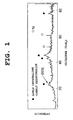
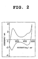
- Fig. 1 and Fig. 2 An X-ray diffraction pattern and cyclic voltammogram of a high-order cobalt compound obtained by subjecting the cobalt hydroxide to the oxidation treatment step and heat treatment step described in step (c) are given in Fig. 1 and Fig. 2, respectively.
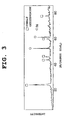
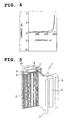
- Fig. 3 and Fig. 4 An X-ray diffraction pattern and cyclic voltammogram of a high-order cobalt compound obtained by impregnating a substrate with cobalt hydroxide particles to produce an electrode and charging the electrode at room temperature to thereby oxidize the cobalt hydroxide are given in Fig. 3 and Fig. 4, respectively.
- Conditions used for determining the cyclic voltammograms are as follows.
- a cellular substrate having a size of 1 cm x 1 cm and impregnated with a high-order cobalt compound was used as a working electrode, and a nickel plate and Hg/HgO were used as a counter electrode and a reference electrode, respectively.
- As an electrolytic solution was used 30% by weight aqueous potassium hydroxide solution. Potential scanning was conducted from 0 to 600 mV at a rate of 5 mV/min.
- the high-order cobalt compound obtained through step (c) can be electrochemically oxidized/reduced and has an electric double-layer capacity. Furthermore, as Fig. 1 shows, the half width for the (003) plane in X-ray diffractometry is 0.7 degrees or larger. Consequently, the high-order cobalt compound obtained through step (c) is lowly crystalline.
- examples of the high-order cobalt compound in the invention include mixtures of at least one cobalt compound selected from Co 3 O 4 , CoHO 2 , and AxCozOyH ⁇ (wherein A is an alkali metal or alkaline earth metal; x,y,z>0; and ⁇ 0) with cobalt oxyhydroxide.
- the nickel electrode can be produced by preparing a slurry or paste from the nickel electrode material according to the invention and coating or impregnating a current collector with the slurry or paste.
- the slurry or paste is prepared by adding either water or water containing a thickener dissolved therein to the electrode material and optionally further adding a binder.
- the thickener include polymeric compounds such as polyethylene glycol and poly(vinyl alcohol), carboxymethyl cellulose, methyl cellulose, and the like.
- the binder include polytetrafluoroethylene, styrene-butadiene rubbers, and the like.
- the nickel electrode is produced by coating or impregnating a current collector with the slurry or paste prepared and drying the slurry or paste applied. It is preferred that after the drying, the resultant structure be pressed to densely fill the inner spaces of the current collector with the electrode material.
- the current collector is not particularly limited as long as it is one in ordinary use in positive electrodes for alkaline storage batteries. However, from the standpoint of ease of dense impregnation with and holding of the electrode material, it is preferred to use a porous object, net structure, or perforated plate each made of a metal.
- the metallic porous object is preferably used a foamed metallic porous object.
- the foamed metallic porous object is a spongy metallic body, and can be produced, for example, by subjecting a foamed resin such as a urethane foam to electroless metal plating and then removing the foamed resin by heating.
- a foamed resin such as a urethane foam
- the metallic net structure is preferably used, for example, a net structure made up of metallic fibers interlaced in a three-dimensional manner, such as a nonwoven fabric.
- the metallic perforated plate can be used, for example, a punching metal, expanded metal, or the like.
- a compound containing one or more rare earth elements is incorporated. (An explanation on this embodiment is omitted here so as to avoid duplication with "Embodiments Employing Rare-Earth Compound" which will be described later.)
- the alkaline storage battery comprises a nickel electrode, a negative electrode, a separator, and an alkaline electrolytic solution.
- the negative electrode generally is one comprising a flexible current collector and disposed thereon a negative-electrode material containing a hydrogen-absorbing alloy.
- the negative electrode should not be construed as being limited thereto.
- the hydrogen-absorbing alloy to be used in the invention is not particularly limited, and a known one can be used.
- the negative electrode employing a hydrogen-absorbing alloy is produced, for example, in the following manner.
- a hydrogen-absorbing alloy powder having a composition represented by Mm ⁇ Ni ⁇ Al ⁇ Co ⁇ Mn ⁇ (wherein Mm is a mischmetal, which is a mixture of rare earth elements such as La, Ce, Pr, and Nd; and ⁇ , ⁇ , ⁇ , ⁇ , and ⁇ each are ⁇ 0) and having a diameter of 75 ⁇ m or smaller is prepared.
- Water containing a thickener dissolved therein and polytetrafluoroethylene as a binder are added to the powder to prepare a paste. This paste is applied to both sides of a punching metal and dried. Thereafter, the coated punching metal is pressed for thickness regulation.
- the separation is not particularly limited, and a known one can be used.
- the separator which is used for preventing short-circuiting between the positive electrode and the negative electrode and for holding an electrolytic solution, is not particularly limited as long as it is usable in alkaline storage batteries.
- examples thereof include nonwoven fabrics formed from polyolefin resin fibers, such as polypropylene resin fibers, or polyamide resin fibers.
- the polyolefin resin fibers or polyamide resin fibers to be used for forming such a nonwoven fabric may have been hydrophilized by the graft polymerization of, e.g., a sulfonating agent or acrylic acid according to need.
- the alkaline electrolytic solution is not particularly limited, and a known one can be used.
- an aqueous solution of at least one of potassium hydroxide, lithium hydroxide, and sodium hydroxide is preferred.
- the battery can have, for example, the structure shown in Fig. 5.
- the alkaline storage battery 1 is a nickel/metal-hydride storage battery and comprises a case 2, a positive electrode (nickel electrode) 3, negative electrode 4, and separator 5 which are disposed in the case 2, and an alkaline electrolytic solution (not shown).
- the case 2 is a nearly cylindrical vessel having an opening 21 at the top, and the bottom thereof serves as a negative terminal.
- the positive electrode 3, negative electrode 4, and separator 5 each are a strip-form member having flexibility.
- the positive electrode 3 and the negative electrode 4 have been disposed in the case 2 in the state of being spirally wound together with the separator 5 sandwiched therebetween.
- the opening 21 of the case 2, which contains an electrolytic solution injected thereinto, has been liquid-tightly sealed with a cover plate 7 through an insulating gasket 6.
- the cover plate 7 has a positive terminal 8 on its upper side. This positive terminal 8 has been connected to the positive electrode 3 through a lead 9, which electrically connects the cover plate 7 to the positive electrode 3.
- the electrolytic solution in the alkaline storage battery 1, it is preferred to use either an aqueous potassium hydroxide solution or an aqueous potassium hydroxide solution containing one or both of lithium hydroxide and sodium hydroxide.
- an aqueous potassium hydroxide solution containing one or both of lithium hydroxide and sodium hydroxide is used, the charge efficiency of the alkaline storage battery 1 can be heightened because this electrolytic solution is effective in shifting the oxygen evolution potential of the positive electrode to the nobler side.
- the amount of such an electrolytic solution to be used varies depending on battery shape. However, in the case of sealed cylindrical batteries, the amount thereof is generally preferably regulated to 0.8 to 1.3 ml per Ah of the capacity of the positive electrode 3.
- the alkaline storage battery 1 In case where the amount of the electrolytic solution is smaller than 0.8 ml, there is a possibility that the alkaline storage battery 1 might have a shortened charge/discharge cycle life. In case where the amount thereof exceeds 1.3 ml, the negative electrode 4 has a reduced gas-absorbing ability, resulting in a possibility that it might be difficult to inhibit the internal pressure of the alkaline storage battery 1 from increasing.
- a compound containing one or more rare earth elements (hereinafter referred to as "rare-earth compound”) be incorporated in the positive active material particles and/or disposed on the surface of the positive-electrode material.
- Examples of the rare earth elements include Er, Tm, Yb, Lu, Y, Ho, and the like.
- Examples of the rare-earth compound include oxides, hydroxide, nitrates, composite oxides, and the like. Immersing any of these compounds in a high-temperature aqueous alkali solution, e.g., 30% by weight aqueous potassium hydroxide solution having a temperature of 80°C, gives the preferred "rare-earth compound having the major peaks" usable in the invention.
- Fig. 6 is shown an X-ray diffraction pattern of "lutetium oxide-lutetium compound" as an example of the rare-earth compound.
- the proportion of this compound in the nickel electrode material is preferably from 0.1 to 20% by weight, especially preferably from 0.5 to 10% by weight.
- the reasons for this are as follows. In case where the proportion thereof is lower than 0.5% by weight, the oxygen evolution potential of the nickel electrode does not sufficiently shift to the nobler side and, hence, there is a possibility in high-temperature charge that the nickel electrode might have poor susceptibility to charge and a sufficient capacity cannot be obtained. In case where the proportion thereof exceeds 10% by weight, the relative amount of the nickel hydroxide is reduced and this may lead to a decrease in capacity and impaired high-rate discharge characteristics.
- the desired electrode material can be produced by adding the rare-earth compound in at least one of the "oxidation treatment step” and "heat treatment step” in step (c) described above.
- the rare-earth compound added should be heat-treated without fail in the "heat treatment step” even when the rare-earth compound is added in the "oxidation treatment step", not to mention in the case of adding the compound in the "heat treatment step”.
- the rare-earth compound in the nickel electrode material obtained has improved stability in the alkaline electrolytic solution. Because of this, the rare-earth compound is inhibited from reacting with the electrolytic solution and dissolving in the electrolytic solution. Consequently, the rare-earth compound is prevented from inhibiting cobalt ion dissolution and cobalt hydroxide precipitation in the electrolytic solution.
- the rare-earth compound is further prevented from depositing on the negative electrode to increase the resistance of the negative electrode. Thus, the decrease in high-rate discharge characteristics attributable to the addition of a rare-earth compound is prevented and improved high-rate discharge characteristics are obtained.
- the addition of a rare-earth compound brings about excellent high-rate charge characteristics. Namely, in the nickel electrode employing the nickel electrode material obtained, the oxygen overvoltage during charge is heightened by the action of the rare-earth compound to shift the oxygen evolution potential to the nobler side and inhibit oxygen evolution. As a result, the efficiency of nickel hydroxide oxidation is heightened.
- the positive-electrode voltage is inhibited from decreasing and is hence kept at a potential at which the high-order cobalt compound constituting a conductive network is stably present. Consequently, the coefficient of use after high-temperature standing is improved.
- the cobalt in the coating layer is sufficiently oxidized to convert the low-order cobalt compound into a high-order cobalt compound in which the cobalt has an oxidation number larger than 2, whereby a satisfactory conductive network is formed.
- the oxidation treatment of the cobalt in the oxidation treatment step proceeds smoothly and a more satisfactory conductive network is formed. Consequently, the coefficient of use of the actual capacity of the positive active material is improved.
- a given amount of electrode material particles were placed in a measuring cylinder. This measuring cylinder was repeatedly dropped from a height of about 10 cm from 100 to 200 times. Thereafter, the space (volume) which was occupied by the electrode material particles and the weight of the particles were measured to determine the tap density thereof.
- Particles to be examined were placed in a tableting machine for forming tablets having a diameter of 8 mm, and a measurement was made at room temperature while applying a pressure of 15,000 N.
- aqueous solution containing nickel sulfate, zinc sulfate, and cobalt sulfate in combination, an aqueous ammonium sulfate solution, and an aqueous sodium hydroxide solution were added little by little to and mixed with a reaction bath containing ammonium sulfate and sodium hydroxide and regulated so as to have a pH of 12.0 ⁇ 0.2 and a temperature of 95 ⁇ 2°, while stirring the reaction bath. Throughout this operation, the pH and temperature of the reaction bath were kept at values within those ranges.
- nickel hydroxide particles containing zinc hydroxide and cobalt hydroxide both incorporated therein in a solid solution state i.e., positive active material particles, were yielded.
- the proportions of the nickel, zinc, and cobalt in the positive active material were regulated to 58% by weight, 3.7% by weight, and 1.2% by weight, respectively (in terms of the proportions of the metals).
- an aqueous solution of cobalt sulfate and an aqueous solution of sodium hydroxide were simultaneously added little by little to and mixed with a reaction bath comprising an aqueous sodium hydroxide solution having a pH regulated to 12.0 ⁇ 0.2 and the positive active material immersed therein, while stirring the reaction bath. Throughout this operation, the pH of the reaction bath was kept at a value within that range.
- a coating layer comprising cobalt hydroxide was formed on the surface of the positive active material particles. Namely, positive-electrode material particles were yielded. The proportion of the coating layer comprising cobalt hydroxide in this positive-electrode material was regulated to 7% by weight.
- the average oxidation number of nickel and cobalt was 2.15.
- aqueous sodium hydroxide solution was added to the positive-electrode material particles which had undergone the oxidation treatment (first step).
- This mixture was heat-treated at 80°C for 2 hours with stirring. Thereafter, the particles were washed with water and dried.
- the nickel electrode material of Example 1-1 was obtained.
- the average oxidation number of nickel and cobalt was 2.15.
- the aqueous sodium hydroxide solution may be gradually added while heating the positive-electrode material particles.
- Example 1-1 The same procedure as in Example 1-1 was conducted, except that the temperature in the heat treatment (second step) was changed. Heat treatment temperatures of 100°C, 120°C, and 140°C were used respectively in Examples 1-2, 1-3, and 1-4. In each of the nickel electrode materials of Examples 1-2 to 1-4, the average oxidation number of nickel and cobalt was 2.15.
- Example 1-5 The same procedure as in Example 1-1 was conducted, except that the alkali concentration and temperature in the heat treatment (second step) were changed. Namely, 40% by weight aqueous sodium hydroxide solution was used and the temperature was changed to 120°C. This is referred to as Example 1-5. In the nickel electrode material of Example 1-5, the average oxidation number of nickel and cobalt was 2.15.
- Example 1-6 The same procedure as in Example 1-1 was conducted, except that the alkali concentration in the oxidation treatment (first step) and the temperature in the heat treatment (second step) were changed. Namely, in the oxidation treatment (first step), water was used in place of the aqueous sodium hydroxide solution. The temperature in the heat treatment (second step) was changed to 120°C. This is referred to as Example 1-6. In the nickel electrode material of Example 1-6, the average oxidation number of nickel and cobalt was 2.15.
- Example 1-7 The same procedure as in Example 1-1 was conducted, except that the alkali concentration in the oxidation treatment (first step) and the temperature in the heat treatment (second step) were changed. Namely, in the oxidation treatment (first step), 20% by weight aqueous sodium hydroxide solution was used. The temperature in the heat treatment (second step) was changed to 120°C. This is referred to as Example 1-7. In the nickel electrode material of Example 1-7, the average oxidation number of nickel and cobalt was 2.15.
- Table 1 shows production conditions for the nickel electrode materials of Examples 1-1 to 1-7.
- Positive-electrode material particles were obtained in the same manner as in Example 1-1.
- the subsequent oxidation treatment (first step) and heat treatment (second step) were omitted.
- the particles obtained are referred to as the nickel electrode material of Comparative Example 1-1.
- the average oxidation number of nickel and cobalt was 2.00.
- Positive-electrode material particles were obtained in the same manner as in Example 1-1. Thereafter, an oxidation treatment (first step) only was conducted. This oxidation treatment was performed in the same manner as in the oxidation treatment in Example 1-1, except that water was used in place of the aqueous sodium hydroxide solution. This is referred to as Comparative Example 1-2. In the nickel electrode material of Comparative Example 1-2, the average oxidation number of nickel and cobalt was 2.15.
- Positive-electrode material particles were obtained in the same manner as in Example 1-1. Thereafter, an oxidation treatment (first step) only was conducted. This oxidation treatment was performed in the same manner as in the oxidation treatment in Example 1-1, except that the concentration of the aqueous sodium hydroxide solution was changed. The concentration was changed to 5% by weight, 10% by weight, 20% by weight, and 30% by weight in Comparative Examples 1-3, 1-4, 1-5, and 1-6, respectively. In each of the nickel electrode materials of Comparative Examples 1-3 to 1-6, the average oxidation number of nickel and cobalt was 2.15.
- Positive-electrode material particles were obtained in the same manner as in Example 1-1. Thereafter, an oxidation treatment (first step) only was conducted. This oxidation treatment was performed in the same manner as in the oxidation treatment in Example 1-1, except that the concentration and temperature of the aqueous sodium hydroxide solution were changed. In Comparative Example 1-7, a concentration of 30% by weight and a temperature of 80°C were used. In Comparative Example 1-8, a concentration of 30% by weight and a temperature of 100°C were used. In each of the nickel electrode materials of Comparative Examples 1-7 and 1-8, the average oxidation number of nickel and cobalt was 2.15.
- Example 1-1 The same procedure as in Example 1-1 was conducted, except that at least one of the alkali concentration and the temperature in the heat treatment (second step) was changed. Namely, in Comparative Example 1-9, the same alkali concentration and a temperature of 40°C were used. In Comparative Example 1-10, the same alkali concentration and a temperature of 60°C were used. In Comparative Example 1-11, 10% by weight aqueous sodium hydroxide solution and a temperature of 120°C were used. In Comparative Example 1-12, 20% by weight aqueous sodium hydroxide solution and a temperature of 120°C were used. In each of the nickel electrode materials of Comparative Examples 1-9 to 1-12, the average oxidation number of nickel and cobalt was 2.15.
- Table 2 shows production conditions for the nickel electrode materials of Comparative Examples 1-1 to 1-12.
- a nickel electrode material, 0.6% by weight CMC (carboxymethyl cellulose) solution, and 40% by weight PTFE (polytetrafluoroethylene) were mixed together in a ratio of 76.7:22.9:0.4 by weight to obtain an electrode material paste.
- a porous cellular nickel substrate was impregnated with the electrode material paste, subsequently dried, and then rolled to produce a nickel electrode having an electrode material impregnation density of 2.6 g/cc and a positive-electrode capacity of 1,450 mAh (theoretical capacity of the nickel hydroxide was regarded as 289 mAh/g).
- each of the nickel electrode materials of Examples 1-1, 1-3, 1-6, and 1-7 and Comparative Examples 1-1, 1-2, and 1-7 was used as the nickel electrode material.
- the nickel electrode material of Comparative Example 1-7 however, impregnation with the given amount of the electrode material was difficult because of a considerable decrease in tap density, resulting in a positive-electrode capacity of 1,250 mAh.
- a nickel electrode and a negative electrode comprising as the main material a hydrogen-absorbing alloy represented by the composite formula Mm 1.0 Ni 4.0 Co 0.7 Mn 0.3 Al 0.3 were spirally wound through a nonwoven polypropylene fabric having a thickness of 100 ⁇ m and inserted into a battery case.
- An electrolytic solution comprising an aqueous solution of both potassium hydroxide and lithium hydroxide was injected into the case, which was then sealed.
- an AA-size nickel/metal-hydride storage battery having a theoretical capacity of 1,450 mAh was produced.
- the battery employing the nickel electrode material of Comparative Example 1-7 had a capacity of 1,250 mAh.
- the nickel electrode materials of Examples 1-1 to 1-7 and Comparative Examples 1-1 to 1-12 were examined for tap density and powder resistance. The results thereof are shown in Table 3 and Table 4. In Tables 3 and 4, values of "average oxidation number (average oxidation number of the nickel in the positive-electrode material particles and the cobalt in the coating layer)" are also shown.
- the nickel electrode material of Comparative Example 1-1 is a positive-electrode material which has undergone neither an oxidation treatment nor a heat treatment and is an insulator of 10 M ⁇ cm or higher.
- the sodium hydroxide concentration of 0% by weight means water.
- Examples 1-1 to 1-7 oxidation treatments were conducted under such conditions as not to result in a decrease in tap density.
- an alkali concentration of 30% by weight and a temperature of 80°C or higher were used to obtain satisfactory values of powder resistance.
- heat treatment temperatures of 40°C and 60°C were used in Comparative Example 1-9 and Comparative Example 1-10, respectively, resulting in a large value of powder resistance in each case. Consequently, heat treatment temperatures of 80°C and higher are effective.
- Example 1-5 an alkali concentration of 40% by weight was used to obtain a satisfactory value of powder resistance.
- alkali concentrations of 10% by weight and 20% by weight were used in Comparative Example 1-11 and Comparative Example 1-12, respectively, resulting in a large value of powder resistance in each case.
- the powder resistance in Comparative Example 1-11 is high and the powder resistance in Comparative Example 1-12 is slightly high. Consequently, alkali concentrations of 30% by weight and higher are effective in the heat treatment.
- the alkali concentration and temperature conditions used in Examples 1-3, 1-4, 1-6, and 1-7 are optimal. Furthermore, such heat treatment conditions result in almost no decrease in tap density. This may be because oxidation of the nickel hydroxide does not occur in such heat treatments.
- the nickel/metal-hydride storage batteries produced by the method described above each were examined to determine the coefficient of use of actual capacity in the following manner.
- the coefficient of use in high-rate discharge was determined in the following manner.
- the electrode material has a significantly high powder resistance and the cobalt compound is thought not to be sufficiently functioning as a conductive network.
- the positive electrode has not been impregnated with the necessary amount of the electrode material because of the reduced tap density of the electrode material.
- the nickel electrode material of Comparative Example 1-1 has undergone no oxidation treatment. Because of this, in the battery employing the nickel electrode material of Comparative Example 1-1, the cobalt hydroxide in the nickel electrode material dissolves in the electrolytic solution, thereafter reprecipitates so as to connect particles to one another, and changes into a conductive cobalt compound upon first charge to form an excellent conductive network. Consequently, the battery employing the nickel electrode material of Comparative Example 1-1 attained an excellent coefficient of use even in high-rate discharge.
- the nickel electrode materials of Examples 1-1, 1-3, 1-6, and 1-7 are free from the dissolution/reprecipitation of the cobalt compound in batteries because they have undergone an oxidation treatment like the nickel electrode materials of the Comparative Examples other than Comparative Example 1-1.
- the batteries employing the nickel electrode materials of Examples 1-1, 1-3, 1-6, and 1-7 have attained the same coefficient of use in high-rate discharge as in Comparative Example 1-1, although the contact resistance among the positive active material particles therein is expected to be higher than in the battery employing the nickel electrode material of Comparative Example 1-1. This is thought to be because the nickel electrode materials of Examples 1-1, 1-3, 1-6, and 1-7 have attained a sufficiently low powder resistance due to the heat treatment conducted after the oxidation treatment in the production thereof.
- An internal-pressure measuring sensor for batteries was attached to the nickel/metal-hydride storage batteries produced by the method described above, and the internal pressure during charge at a charge current of 1,450 mA (1 ItA) was measured.
- the internal pressures shown in Table 5 are values obtained after 1.5-hour charge.
- the difference in internal pressure between the batteries employing the nickel electrode materials of Examples 1-1, 1-3, 1-6, and 1-7 and the battery employing the nickel electrode material of Comparative Example 1-1 is attributable to a difference in discharge reserve amount generated in the negative electrode.
- oxygen gas evolution and hydrogen gas evolution occur at the positive electrode and the negative electrode, respectively, to elevate the internal pressure of the battery.
- the hydrogen gas evolution at the negative electrode is influenced by the charge reserve amount of the negative electrode; hydrogen gas is apt to generate when the charge reserve amount is small.
- causes of a decrease in charge reserve amount include the generation of discharge reserve.
- the nickel/metal-hydride storage batteries produced by the method described above were examined to determine the recovered coefficient of use after over discharge.
- each battery was conducted in the following manner. Namely, a cycle consisting of 0.1-ItA charge and 0.2 ItA discharge was repeated several times. Thereafter, the battery in a discharged state was externally short-circuited through a 4- ⁇ resistor and allowed to stand in a 60°C atmosphere for 3 days.
- the positive-electrode potential approaches the negative-electrode potential and the battery voltage becomes almost 0 V.
- the cobalt compound in the positive electrode changes into a cobalt compound having high resistance. This is thought to be causative of the decrease in the coefficient of use through over discharge in the batteries employing the nickel electrode materials of Comparative Examples 1-1 and 1-2.
- lithium hydroxide or potassium hydroxide may be employed in place of sodium hydroxide because alkali concentration considerably influences a decrease in the powder resistance of the electrode materials.
- use of lithium hydroxide alone is not effective because it does not dissolve in water in a high concentration.
- a positive active material was synthesized by the ammine complex salt method in the following manner.
- An aqueous solution containing nickel sulfate, zinc sulfate, and cobalt sulfate in combination and an aqueous ammonium sulfate solution were simultaneously and continuously added little by little to and mixed with an alkaline aqueous solution having a pH regulated to 12.0 ⁇ 0.2, while stirring the alkaline solution.
- an appropriate amount of an aqueous sodium hydroxide solution was dropped into the reaction bath to keep the pH of the reaction bath in the 12.0 ⁇ 0.2 range.
- the temperature of the reaction bath during the mixing operation was kept at 45 ⁇ 2°C.
- nickel hydroxide solid solution particles containing zinc and cobalt both incorporated therein in a solid solution state i.e., positive active material particles.
- the proportions of the nickel, zinc, and cobalt in the positive active material were regulated to 58% by weight, 3.7% by weight, and 1.2% by weight, respectively, in terms of the proportions of the metals.
- the positive active material particles were dispersed in an alkaline aqueous solution having a pH regulated to 12.0 ⁇ 0.2.
- An aqueous cobalt sulfate solution and an aqueous sodium hydroxide solution were simultaneously and continuously added little by little to the dispersion while stirring the dispersion.
- the pH of the reaction bath was kept at 12.0 ⁇ 0.2 by regulating the rate of addition of the sodium hydroxide.
- a coating layer comprising cobalt hydroxide was formed on the surface of the positive active material particles. Namely, positive-electrode material particles were yielded.
- the proportion of the coating layer comprising cobalt hydroxide in this positive-electrode material was regulated to 7% by weight.
- the nickel hydroxide in the positive-electrode material obtained had a peak intensity ratio (100)/(001) of 0.60, a peak intensity ratio (101)/(001) of 0.60, and a half width of the peak for the (101) plane of 1.1 degree.
- Example 1-1 An oxidation treatment was conducted in the same manner as in Example 1-1. Thereafter, the positive-electrode material particles were taken out of the reaction bath, washed, and dehydrated. In the positive-electrode material which had undergone this oxidation treatment, the average oxidation number of nickel and cobalt was 2.15.
- Example 2-1 A heat treatment was conducted in the same manner as in Example 1-1, except that the treatment was performed "at 80°C for 30 minutes". Thus, a nickel electrode material of Example 2-1 was obtained. In the nickel electrode material of Example 2-1, the average oxidation number of nickel and cobalt was 2.15.
- the nickel hydroxide in the nickel electrode material obtained had a peak intensity ratio (100) / (001) of 0.60, a peak intensity ratio (101) / (001) of 0.60, and a half width of the peak for the (101) plane of from 1.0 to 1.1 degree.
- a nickel electrode (theoretical capacity of the nickel hydroxide was regarded as 289 mAh/g) was produced by the same method as in Example 1.
- An AA-size nickel/metal-hydride storage battery having a theoretical capacity of 1,450 mAh was produced by the same method as in Example 1.
- a nickel electrode material was obtained in the same manner as in Example 2-1, except that the treatment period in the heat treatment (second step) in Example 2-1 was changed to 5 hours. Furthermore, a nickel electrode and a nickel/metal-hydride storage battery were produced in the same manner as in Example 2-1.
- the average oxidation number of nickel and cobalt was 2.15.
- the nickel hydroxide in the nickel electrode material of Example 2-2 had a peak intensity ratio (100)/(001) of 0.50, a peak intensity ratio (101)/(001) of 0.50, and a half width of the peak for the (101) plane of 0.9 degrees.
- a nickel electrode material was obtained in the same manner as in Example 2-1, except that the treatment period in the heat treatment (second step) in Example 2-1 was changed to 10 hours. Furthermore, a nickel electrode and a nickel/metal-hydride storage battery were produced in the same manner as in Example 2-1.
- the average oxidation number of nickel and cobalt was 2.15.
- the nickel hydroxide in the nickel electrode material of Example 2-3 had a peak intensity ratio (100)/(001) of 0.50, a peak intensity ratio (101)/(001) of 0.50, and a half width of the peak for the (101) plane of 0.9 degrees.
- a nickel electrode material was obtained in the same manner as in Example 2-1, except that the treatment temperature and treatment period in the heat treatment (second step) in Example 2-1 were changed to 120°C and 1 hour, respectively. Furthermore, a nickel electrode and a nickel/metal-hydride storage battery were produced in the same manner as in Example 2-1.
- the average oxidation number of nickel and cobalt was 2.15.
- the nickel hydroxide in the nickel electrode material of Example 2-4 had a peak intensity ratio (100)/(001) of 0.55, a peak intensity ratio (101)/(001) of 0.55, and a half width of the peak for the (101) plane of 1.0 degree.
- a nickel electrode material was obtained in the same manner as in Example 2-1, except that the treatment period in the heat treatment step in Example 2-1 was changed to 16 hours. Furthermore, a nickel electrode and a nickel/metal-hydride storage battery were produced in the same manner as in Example 2-1.
- the average oxidation number of nickel and cobalt was 2.15.
- the nickel hydroxide in the nickel electrode material of Reference Example 2-1 had a peak intensity ratio (100)/(001) of 0.47, a peak intensity ratio (101)/(001) of 0.47, and a half width of the peak for the (101) plane of 0.8 degrees.
- Table 6 shows production conditions for each of the nickel electrode materials of Examples 2-1 to 2-4 and Reference Example 2-1.
- First Step oxygen treatment
- Second Step heat treatment
- Aqueous NaOH solution wt%)
- Temperature °C
- Temperature °C Hours
- Example 2-1 10 60 0.5 30 80
- Example 2-2 10 60 0.5 30 80 5
- Example 2-3 10
- Example 2-4 10
- 10 60 0.5 30 80 16
- the nickel electrode materials of Examples 2-1 to 2-4 and Reference Example 2-1 were examined for tap density and powder resistance. The results thereof are shown in Table 7 (1). In Table 7 are also shown "average oxidation number: average oxidation number of the nickel in the positive-electrode material particles and the cobalt in the coating layer", “peak intensity ratios: (100)/(001) and (101)/(001)", and "half width: half width of the peak for the (101) plane”.
- Example 2-1 2.15 2.20 20 0.60 0.60 1.0-1.1
- Example 2-2 2.15 2.20 21 0.50 0.50 0.9
- Example 2-3 2.15 2.20 19 0.50 0.50 0.9
- Example 2-4 2.15 2.20 28 0.55 0.55 1.0 Reference Example 2-1 2.15 2.21 16 0.47 0.47 0.8
- Example 7 (2) shows that the batteries of Examples 2-1 to 2-4 had a coefficient of use of actual capacity of 100%, while the battery of Reference Example 2-1 had a coefficient of use of actual capacity of 95%.
- Coefficient of use in 0.2-ItA discharge Example 2-1 100
- Example 2-2 100
- Example 2-3 100
- Example 2-4 100 Reference Example 2-1 95
- a positive active material containing cobalt and zinc in a solid solution state was produced by the same method as that described in Example 2-1.
- the proportions of the cobalt and zinc incorporated in a solid solution state were regulated to 0.5% by weight and 3.5% by weight, respectively, in terms of the proportions of the metals.
- a coating layer of cobalt hydroxide was formed on the surface of the positive active material by the same method as that described in Example 2-1. Thus, a positive-electrode material was produced. The proportion of all cobalt in this positive-electrode material was regulated to 4.0% by weight in terms of the proportion of the metal.
- proportion means the value based on the weight of the positive active material and coating layer (the weight excludes that of any ingredient other than the components of the positive-electrode material, such as, e.g., an electrolytic solution).
- a heat treatment was conducted by the same method as in Example 2-1 to obtain a nickel electrode material.
- the nickel and cobalt in this nickel electrode material had an average oxidation number of 2.15.
- a nickel electrode was produced by the same method as in Example 2-1.
- An AA-size nickel/metal-hydride battery having a theoretical capacity of 1,450 mAh was produced by the same method as in Example 2-1.
- Example 3-1 The same procedure as in Example 3-1 was conducted, except that the proportions of the cobalt and zinc incorporated in a solid solution state into the positive active material were regulated to 1.5% by weight and 3.5% by weight, respectively, in terms of the proportions of the metals, and that the proportion of all cobalt in the positive-electrode material was regulated to 5.5% by weight in terms of the proportion of the metal. (Average oxidation number of nickel and cobalt in the positive-electrode material: 2.15)
- Example 3-1 The same procedure as in Example 3-1 was conducted, except that the proportions of the cobalt and zinc incorporated in a solid solution state into the positive active material were regulated to 4.0% by weight and 3.5% by weight, respectively, in terms of the proportions of the metals, and that the proportion of all cobalt in the positive-electrode material was regulated to 8.0% by weight in terms of the proportion of the metal. (Average oxidation number of nickel and cobalt in the positive-electrode material: 2.15)
- Example 3-1 The same procedure as in Example 3-1 was conducted, except that the proportions of the cobalt and zinc incorporated in a solid solution state into the positive active material were regulated to 1.5% by weight and 1.0% by weight, respectively, in terms of the proportions of the metals, and that the proportion of all cobalt in the positive-electrode material was regulated to 5.5% by weight in terms of the proportion of the metal. (Average oxidation number of nickel and cobalt in the positive-electrode material: 2.15)
- Example 3-1 The same procedure as in Example 3-1 was conducted, except that the proportions of the cobalt and zinc incorporated in a solid solution state into the positive active material were regulated to 1.5% by weight and 5.0% by weight, respectively, in terms of the proportions of the metals, and that the proportion of all cobalt in the positive-electrode material was regulated to 5.5% by weight in terms of the proportion of the metal. (Average oxidation number of nickel and cobalt in the positive-electrode material: 2.15)
- Example 3-1 The same procedure as in Example 3-1 was conducted, except that the proportions of the cobalt and zinc incorporated in a solid solution state into the positive active material were regulated to 1.5% by weight and 3.5% by weight, respectively, in terms of the proportions of the metals, and that the proportion of all cobalt in the positive-electrode material was regulated to 2.5% by weight in terms of the proportion of the metal. (Average oxidation number of nickel and cobalt in the positive-electrode material: 2.15)
- Example 3-1 The same procedure as in Example 3-1 was conducted, except that the proportions of the cobalt and zinc incorporated in a solid solution state into the positive active material were regulated to 0.5% by weight and 3.5% by weight, respectively, in terms of the proportions of the metals, and that the proportion of all cobalt in the positive-electrode material was regulated to 3.0% by weight in terms of the proportion of the metal. (Average oxidation number of nickel and cobalt in the positive-electrode material: 2.15)
- Example 3-1 The same procedure as in Example 3-1 was conducted, except that the proportions of the cobalt and zinc incorporated in a solid solution state into the positive active material were regulated to 1.5% by weight and 3.5% by weight, respectively, in terms of the proportions of the metals, that the proportion of all cobalt in the positive-electrode material was regulated to 5.5% by weight in terms of the proportion of the metal, and that the average oxidation number of the nickel and cobalt in the positive-electrode material was regulated to 2.04.
- Example 3-1 The same procedure as in Example 3-1 was conducted, except that the proportions of the cobalt and zinc incorporated in a solid solution state into the positive active material were regulated to 1.5% by weight and 3.5% by weight, respectively, in terms of the proportions of the metals, that the proportion of all cobalt in the positive-electrode material was regulated to 5.5% by weight in terms of the proportion of the metal, and that the average oxidation number of the nickel and cobalt in the positive-electrode material was regulated to 2.4.
- Example 3-1 The same procedure as in Example 3-1 was conducted, except that the proportions of the cobalt and zinc incorporated in a solid solution state into the positive active material were regulated to 6.0% by weight and 3.5% by weight, respectively, in terms of the proportions of the metals, and that the proportion of all cobalt in the positive-electrode material was regulated to 10.0% by weight in terms of the proportion of the metal. (Average oxidation number of nickel and cobalt in the positive-electrode material: 2.15)
- Example 3-1 The same procedure as in Example 3-1 was conducted, except that the proportions of the cobalt and zinc incorporated in a solid solution state into the positive active material were regulated to 1.5% by weight and 0% by weight, respectively, in terms of the proportions of the metals, and that the proportion of all cobalt in the positive-electrode material was regulated to 5.5% by weight in terms of the proportion of the metal. (Average oxidation number of nickel and cobalt in the positive-electrode material: 2.15)
- Example 3-1 The same procedure as in Example 3-1 was conducted, except that the proportions of the cobalt and zinc incorporated in a solid solution state into the positive active material were regulated to 1.5% by weight and 7.0% by weight, respectively, in terms of the proportions of the metals, and that the proportion of all cobalt in the positive-electrode material was regulated to 5.5% by weight in terms of the proportion of the metal. (Average oxidation number of nickel and cobalt in the positive-electrode material: 2.15)
- Example 3-1 The same procedure as in Example 3-1 was conducted, except that the proportions of the cobalt and zinc incorporated in a solid solution state into the positive active material were regulated to 1.5% by weight and 3.5% by weight, respectively, in terms of the proportions of the metals, and that the proportion of all cobalt in the positive-electrode material was regulated to 11.0% by weight in terms of the proportion of the metal. (Average oxidation number of nickel and cobalt in the positive-electrode material: 2.15)
- Example 3-1 The same procedure as in Example 3-1 was conducted, except that the proportions of the cobalt and zinc incorporated in a solid solution state into the positive active material were regulated to 1.5% by weight and 3.5% by weight, respectively, in terms of the proportions of the metals, that the proportion of all cobalt in the positive-electrode material was regulated to 5.5% by weight in terms of the proportion of the metal, and that the average oxidation number of the nickel and cobalt in the positive-electrode material was regulated to 2.0.
- Example 3-1 The same procedure as in Example 3-1 was conducted, except that the proportions of the cobalt and zinc incorporated in a solid solution state into the positive active material were regulated to 1.5% by weight and 3.5% by weight, respectively, in terms of the proportions of the metals, that the proportion of all cobalt in the positive-electrode material was regulated to 5.5% by weight in terms of the proportion of the metal, and that the average oxidation number of the nickel and cobalt in the positive-electrode material was regulated to 2.5.
- Example 3-1 to 3-9 The nickel electrode materials of Examples 3-1 to 3-9, Reference Examples 3-1 to 3-4, and Comparative Examples 3-1 and 3-2 were examined to determine the coefficient of use of actual capacity by the same method as the measuring method described in Example 1. The results thereof are shown in Table 8. With respect to the "coefficient of use of actual capacity (%)" shown in Table 8, the value for Example 3-2 is taken as "100%", and the values for the other Examples and for the Reference Examples and Comparative Examples are shown in terms of proportion to the value for Example 3-2.
- Example 3-2 The batteries of Example 3-2, Example 3-8, Example 3-9, Comparative Example 3-1, and Comparative Example 3-2 were examined to determine the discharge reserve amount.
- the discharge reserve amount was determined by the following method.
- charge/discharge was repeated by repeatedly conducting "a cycle” consisting of "120% charge at 1 ItA and discharge at 1 ItA to a final voltage of 1.0 V". After “ten cycles” of charge/discharge were conducted under these conditions, the battery was discharged at 0.2 ItA to a final voltage of 1.0 V. After the discharge, the battery was disassembled, and the negative electrode recovered was placed in a sealed beaker filled with distilled water. This beaker was heated with a water bath to measure the amount of the hydrogen remaining in the negative electrode. The hydrogen amount obtained was converted to quantity of electricity. The proportion of this converted value to the theoretical capacity of the positive electrode was taken as "discharge reserve amount (%)". The results are shown in Table 8.
- Examples 3-1 to 3-9 Reference Examples 3-1 to 3-4, and Comparative Examples 3-1 and 3-2, negative-electrode alloys having the following compositions were used.
- the alloy types used are shown in Table 8.
- the batteries of Examples 3-1 to 3-9 each are excellent in the coefficient of use, active-material impregnation amount, and cycle characteristics.
- Example 3-2 shows the following.
- Comparative Example 3-1 shows the discharge reserve amount increased considerably.
- a nickel electrode was obtained through the following step (1) to step (4).
- a coating layer comprising ⁇ -cobalt hydroxide was formed on the surface of positive active material particles comprising a nickel hydroxide solid solution containing zinc and cobalt incorporated in a solid solution state in amounts of 3 parts by weight and 6 parts by weight, respectively, in terms of the proportions of the metals.
- a positive-electrode material was obtained.
- the proportion of the coating layer comprising ⁇ -cobalt hydroxide in the positive-electrode material was regulated to 4% by weight.
- Eighty parts by weight of the positive-electrode material was mixed with 20 parts by weight of an aqueous carboxymethyl cellulose solution as a binder to prepare a paste.
- the paste was evenly applied to a porous nickel substrate as a current collector and dried. Thereafter, the porous substrate was pressed and cut into an electrode size for AAA-size batteries. Thus, an electrode body having a capacity of 750 mAh was obtained.
- the electrode body was immersed in 500 g of 10% by weight aqueous sodium hydroxide solution and subjected to an oxidation treatment with K 2 S 2 O 8 as an oxidizing agent at 50°C. Furthermore, the electrode body was immersed in 500 g of 30% by weight aqueous sodium hydroxide solution and heat-treated at 100°C. The electrode body thus treated was dried in an 80°C argon atmosphere to obtain a nickel electrode. The K 2 S 2 O 8 was added in an amount of 0.4 g per g of the positive-electrode material. (Although the treated electrode body was dried in an argon atmosphere, the drying in the invention should not be construed as being limited to such drying in an "argon atmosphere".)
- a nickel electrode was obtained in same manner as in Example 4-1, except that the proportion of the coating layer comprising ⁇ -cobalt hydroxide in the positive-electrode material was changed to 6% by weight.
- a nickel electrode was obtained in same manner as in Example 4-1, except that the proportion of the coating layer comprising ⁇ -cobalt hydroxide in the positive-electrode material was changed to 10% by weight.
- a nickel electrode was obtained in same manner as in Example 4-1, except that the proportion of the coating layer comprising ⁇ -cobalt hydroxide in the positive-electrode material was changed to 2% by weight.
- a nickel electrode was obtained in same manner as in Example 4-1, except that the proportion of the coating layer comprising ⁇ -cobalt hydroxide in the positive-electrode material was changed to 15% by weight.
- a positive-electrode material was obtained in the same manner as in step (1) in Example 4-1.
- the positive-electrode material was mixed with lutetium oxide as a rare-earth compound to obtain mixed particles consisting of particles of the positive-electrode material and the rare-earth compound disposed on the surface of the particles.
- the proportion of the rare-earth compound in the mixed particles was regulated to 0.5% by weight.
- Example 4-1 The same procedure as in step (2) to step (4) in Example 4-1 was conducted, except that the mixed particles were used in place of the positive-electrode material. Thus, a nickel electrode was obtained.
- a nickel electrode was obtained in the same manner as in Example 4-6, except that the proportion of the rare-earth compound in the mixed particles was changed to 3.5% by weight.
- a nickel electrode was obtained in the same manner as in Example 3-6, except that the proportion of the rare-earth compound in the mixed particles was changed to 10% by weight.
- a nickel electrode was obtained in the same manner as in Example 4-6, except that the proportion of the rare-earth compound in the mixed particles was changed to 0.1% by weight.
- a nickel electrode was obtained in the same manner as in Example 4-6, except that the proportion of the rare-earth compound in the mixed particles was changed to 15% by weight.
- a nickel electrode was obtained in the same manner as in Example 4-6, except that a rare-earth composite oxide containing 0.5% by weight Er, 1.5% by weight Tm, 85% by weight Yb, and 13% by weight Lu (each based on the sum of the Er, Tm, Yb, and Lu contained in the rare-earth compound) was used as a rare-earth compound, and that the proportion of this rare-earth composite oxide in the mixed particles was regulated to 2% by weight.
- a rare-earth composite compound which contained 0.5% by weight Er, 1.5% by weight Tm, 85% by weight Yb, and 13% by weight Lu (each based on the sum of the Er, Tm, Yb, and Lu contained in the rare-earth compound) and which, in X-ray diffracto
- An aqueous solution of given amounts of nickel nitrate, cobalt nitrate, zinc nitrate, and lutetium nitrate, an aqueous ammonium sulfate solution, and an aqueous sodium hydroxide solution were added little by little to and mixed with a reaction bath containing ammonium sulfate and sodium hydroxide and regulated so as to have a pH of 12.0 ⁇ 0.2 and a temperature of 45 ⁇ 2°C, while stirring the reaction bath. Throughout this operation, the pH and temperature of the reaction bath were regulated so as to be within those ranges.
- positive active material particles comprised a nickel hydroxide solid solution containing 1.8% by weight lutetium, which is a rare earth element, and further containing 2.9% by weight zinc and 5.9% by weight cobalt both incorporated in a solid solution state.
- a cellular substrate made of nickel was impregnated with the positive active material particles.
- a nickel electrode was obtained through the following step (1) to step (3).
- a coating layer comprising ⁇ -cobalt hydroxide was formed on the surface of positive active material particles comprising a nickel hydroxide solid solution containing zinc and cobalt incorporated in a solid solution state in amounts of 3% by weight and 6% by weight, respectively, in terms of the proportions of the metals.
- a positive-electrode material was obtained.
- the proportion of the coating layer comprising ⁇ -cobalt hydroxide in the positive-electrode material was regulated to 6% by weight.
- Eighty parts by weight of the positive-electrode material was mixed with 20 parts by weight of an aqueous carboxymethyl cellulose solution as a binder to prepare a paste.
- the paste was evenly applied to a porous nickel substrate as a current collector and dried. Thereafter, the porous substrate was pressed and cut into an electrode size for AAA-size batteries. Thus, an electrode body having a capacity of 750 mAh was obtained as a nickel electrode.
- a positive-electrode material was obtained in the same manner as in step (1) in Comparative Example 4-1.
- the positive-electrode material was mixed with lutetium oxide as a rare-earth compound to obtain mixed particles consisting of particles of the positive-electrode material and the rare-earth compound disposed on the surface of the particles.
- the proportion of the rare-earth compound in the mixed particles was regulated to 3.5% by weight.
- step (2) and step (3) in Comparative Example 4-1 were conducted, except that the mixed particles were used in place of the positive-electrode material. Thus, a nickel electrode was obtained.
- a positive-electrode material was obtained in the same manner as in step (1) in Comparative Example 4-1.
- the positive-electrode material was treated by the method described in JP-A-2000-223119. Namely, the positive-electrode material was first sprayed with 35% by weight aqueous sodium hydroxide solution in an amount 5 times the amount of the cobalt, while keeping the temperature of the positive-electrode material at 60°C. Thereafter, the positive-electrode material was heated to 90°C. A hundred grams of this positive-electrode material was immersed in an aqueous solution prepared by dissolving 125 ml of 12% by weight sodium hypochlorite in 1,000 ml of 10% by weight aqueous sodium hydroxide solution. The resultant mixture was stirred for 10 minutes.
- a positive-electrode material was obtained in the same manner as in step (1) in Comparative Example 4-1. Subsequently, the positive-electrode material was treated in the same manner as in Comparative Example 4-3.
- the positive-electrode material which had been treated was then mixed with lutetium oxide as a rate-earth compound to obtain mixed particles consisting of particles of the positive-electrode material and the rare-earth compound disposed on the surface of the particles.
- the proportion of the rare-earth compound in the mixed particles was regulated to 3.5% by weight.
- step (2) and step (3) in Comparative Example 4-1 The same procedure as in step (2) and step (3) in Comparative Example 4-1 was conducted, except that the mixed particles were used in place of the positive-electrode material. Thus, a nickel electrode was obtained.
- a negative electrode was produced in the following manner.
- a thickener was added to a powder of a hydrogen-absorbing alloy having the CaCu 5 type structure and having a composition represented by MmNi 3.5 Co 0.8 Mn 0.4 Al 0.3 (wherein Mm means a mischmetal which is a mixture of rare earth elements such as La, Ce, Pr, Nd, and Sm) to prepare a paste.
- Mm means a mischmetal which is a mixture of rare earth elements such as La, Ce, Pr, Nd, and Sm
- this paste was applied to both sides of a perforated steel plate as a current collector and dried. This perforated steel plate was pressed and cut into an electrode size for AAA-size batteries. Thus, a negative electrode was obtained.
- the capacity of this negative electrode was regulated to 1.6 times the capacity of the nickel electrode.
- the nickel electrode and the negative electrode were wound together with a separator sandwiched therebetween to produce a group of electrodes.
- This electrode group was placed in a battery case, into which an electrolytic solution was injected.
- This battery case was sealed to produce a battery.
- the separator was used a nonwoven fabric of a polypropylene resin in which acrylic acid had been graft-polymerized.
- the battery case was used a cylindrical case.
- the electrolytic solution was used a mixture of 6.8 mol/l aqueous potassium hydroxide solution and 0.5 mol/l aqueous lithium hydroxide solution.
- a cylindrical, AAA-size, sealed nickel/metal-hydride storage battery having a capacity of 750 mAh was obtained.
- the electrolytic solution was injected in an amount of 0.9 ml per Ah of the capacity of the positive electrode.
- the electrode materials constituting the nickel electrodes of Examples 4-1 to 4-14 and Comparative Examples 4-1 to 4-4 were examined for average oxidation number (average oxidation number of the nickel in the positive-electrode material particles and the cobalt in the coating layer), tap density, and powder resistance. The results thereof are shown in Table 9.
- Example 4-1 2.25 2.2 10
- Example 4-2 2.25 2.2 4
- Example 4-3 2.25 2.1 2
- Example 4-4 2.25 2.3 20
- Example 4-5 2.25 2.0 1
- Example 4-6 2.25 2.2 4
- Example 4-7 2.25 2.2 5
- Example 4-8 2.25 2.3 20
- Example 4-9 2.25 2.2 4
- Example 4-10 2.25 2.3 40
- Example 4-11 2.25 2.2 5
- Example 4-12 2.25 2.2 5
- Example 4-13 2.25 2.2 5
- Example 4-14 2.25 2.2 5 Comparative Example 4-1 2.0 2.2 >10 6 Comparative Example 4-2 2.0 2.2 >10 6 Comparative Example 4-3 2.3 1.9 100 Comparative Example 4-4 2.3 1.9 120
- Each of the nickel electrodes of Examples 4-1 to 4-14 and Comparative Examples 4-1 to 4-4 was superposed on a negative electrode which had undergone a sufficient activation treatment beforehand, through a separator comprising a nonwoven fabric formed from polyolefin resin fibers. An even pressure was applied to this assembly to produce an open type test cell containing an electrolytic solution in an excess amount.
- the open type test cell was charged at a charge current of 0.1 ItA for 15 hours, paused for 1 hour, and then discharged at 0.2 ItA to a final voltage of 0 V based on Hg/HgO as a reference electrode.
- This charge/discharge cycle was repeatedly conducted 10 times to determine the discharge capacity in this operation.
- the cell was discharged at 5 ItA, and the discharge capacity in this discharge was determined. The results are shown in Table 10.
- the coefficient of use of positive electrode shown in Table 10 means the proportion of the capacity obtained in 0.2-ItA discharge to the theoretical capacity calculated on the assumption that the nickel hydroxide has undergone a one-electron reaction.
- the batteries employing the nickel electrodes of the Examples can attain a preferred discharge capacity as compared with the batteries employing the nickel electrodes of the Comparative Examples.
- a comparison between Example 4-1 and Example 4-4 shows that Example 4-1 attains a higher coefficient of use of the positive electrode.
- a comparison between Example 4-3 and Example 4-5 shows that Example 4-3 attains a slightly higher coefficient of use of the positive electrode. Consequently, the proportion of the coating layer comprising ⁇ -cobalt hydroxide is preferably from 4 to 10% by weight.
- the open type test cell was charged at a charge current of 0.1 ItA for 15 hours, paused for 1 hour, and then discharged at 0.2 ItA to a final voltage of 0 V based on the Hg/HgO as a reference electrode.
- This charge/discharge cycle was repeatedly conducted 10 times. In the 11th cycle, the battery was discharged at 5 ItA to examined the discharge capacity in this discharge. Thereafter, at 50°C, the battery was charged at a charge current of 0.1 ItA for 15 hours, paused for 1 hour, and then discharged at 0.2 ItA to a final voltage of 0 V based on Hg/HgO as a reference electrode. This charge/discharge cycle at 50°C was repeated until the discharge capacity became stable.
- the charge efficiency shown in Table 11 means the proportion of the capacity obtained in 0.2-ItA discharge at 50°C to the theoretical capacity calculated on the assumption that the nickel hydroxide has undergone a one-electron reaction.
- the batteries employing the nickel electrodes of the Examples can attain a preferred charge efficiency at the high temperature as compared with the batteries employing the nickel electrodes of the Comparative Examples.
- a comparison between Example 4-6 and Example 4-9 shows that Example 4-6 attains a higher charge efficiency.
- a comparison between Example 4-8 and Example 4-10 shows that Example 4-8 attains a slightly higher charge efficiency. Consequently, the proportion of the compound containing one or more rare earth elements is preferably from 0.5 to 10% by weight.
- the discharge recovery was determined through the following steps (1) to (3).
- the discharge recovery was determined through the following steps (1) to (3).
- the discharge recovery after over discharge shown in Table 12 means the proportion of the capacity obtained in 0.2-ItA discharge at 20°C after over discharge to the theoretical battery capacity calculated on the assumption that the nickel hydroxide has undergone a one-electron reaction.
- the discharge recovery after standing shown in Table 12 means the proportion of the capacity obtained in 0.2-ItA discharge at 20°C to the theoretical battery capacity calculated on the assumption that the nickel hydroxide has undergone a one-electron reaction.
- the batteries employing the nickel electrodes of the Examples are satisfactory in discharge recovery after over discharge and discharge recovery after standing.
- a positive-electrode material produced in the same manner as in “Production of Positive Active Material” and “Production of Positive-Electrode Material (Coating with Cobalt Hydroxide)" in Example 1-1 was subjected to the following oxidation treatment and heat treatment to obtain a nickel electrode material.
- Example 4-1 To the positive-electrode material particles which had undergone the oxidation treatment were added 20 g of 30% by weight aqueous sodium hydroxide solution and 3.5 g of Yb 2 O 3 . This mixture was heat-treated at 120°C for 2 hours with stirring. After completion of the reaction, the positive-electrode material particles were taken out of the reaction bath, filtered, washed with water, and dried. In the positive-electrode material obtained, the average oxidation number of nickel and cobalt was 2.15. This positive-electrode material obtained is referred to as the nickel electrode material of Example 4-1.
- the nickel electrode material obtained was mixed with 0.6% by weight carboxymethyl cellulose solution and 60% by weight polytetrafluoroethylene solution in a ratio of 76.7:22.9:0.4 by weight to prepare an electrode material paste.
- a porous cellular nickel substrate was impregnated with the electrode material paste, subsequently dried, and then rolled to produce a nickel electrode having an electrode material impregnation density of 2.6 g/ml and a positive-electrode capacity of 1,450 mAh (theoretical capacity of the nickel hydroxide was regarded as 289 mAh/g).
- An alkaline storage battery was produced by the same method as in Example 1. Namely, the nickel electrode and a negative electrode comprising as the main material a hydrogen-absorbing alloy represented by the composite formula Mm 1.0 Ni 4.0 Co 0.7 Mn 0.3 Al 0.3 were spirally wound through a nonwoven polypropylene fabric having a thickness of 100 ⁇ m and inserted into a battery case. Thereafter, an electrolytic solution comprising an aqueous potassium hydroxide solution and an aqueous lithium hydroxide solution was injected into the battery case, which was then sealed. Thus, an AA-size nickel/metal-hydride storage battery having a theoretical capacity of 1,450 mAh was produced. This is referred to as the battery of Example 5-1.
- Nickel electrode materials of Examples 5-2 to 5-5 were produced in the same manner as in Example 5-1, except that each of Er 2 O 3 , Lu 2 O 3 , Tm 2 O 3 , and Y 2 O 3 was used in place of Yb 2 O 3 in the heat treatment (second step) in Example 5-1.
- the average oxidation number of nickel and cobalt was 2.15.
- Example 5-2 to 5-5 AA-size nickel/metal-hydride storage batteries having a theoretical capacity of 1,450 mAh were further produced in the same manner as in Example 5-1. These are referred to as the batteries of Examples 5-2 to 5-5.
- a nickel electrode material of Example 5-6 was produced in the same manner as in Example 5-1, except that 3.5 g of Yb 2 O 3 also was added to the aqueous sodium hydroxide solution in the oxidation treatment (first step) in Example 5-1, and that the addition of Yb 2 O 3 in the heat treatment step in Example 5-1 was omitted.
- the average oxidation number of nickel and cobalt was 2.15.
- Example 5-6 Using the nickel electrode material of Example 5-6, an AA-size nickel/metal-hydride storage battery having a theoretical capacity of 1,450 mAh was further produced in the same manner as in Example 5-1. This is referred to as the battery of Example 5-6.
- a positive-electrode material was obtained in the same manner as in Example 5-1. The subsequent oxidation treatment and heat treatment were omitted.
- the positive-electrode material obtained is referred to as the nickel electrode material of Comparative Example 5-1.
- the average oxidation number of nickel and cobalt was 2.00.
- Example 5-1 Using the nickel electrode material of Comparative Example 5-1, an AA-size nickel/metal-hydride storage battery having a theoretical capacity of 1,450 mAh was further produced in the same manner as in Example 5-1. This is referred to as the battery of Comparative Example 5-1.
- the nickel electrode material of Comparative Example 5-2 is the same as that of Comparative Example 5-1. Subsequently, the nickel electrode material of Comparative Example 5-2, Yb 2 O 3 , 0.6% by weight carboxymethyl cellulose solution, and 60% by weight polytetrafluoroethylene solution were mixed together in a ratio of 74.7:2.6:22.3:0.4 by weight to prepare an electrode material paste. This electrode material paste was used to produce a nickel electrode and a nickel/metal-hydride storage battery in the same manner as in Example 5-1. This battery is referred to as the battery of Comparative Example 5-2.
- a nickel electrode material of Reference Example 5-1 was produced in the same manner as in Example 5-1, except that the addition of Yb 2 O 3 in the heat treatment step in Example 5-1 was omitted.
- the average oxidation number of nickel and cobalt was 2.15.
- Example 5-1 Using the nickel electrode material of Reference Example 5-1, an AA-size nickel/metal-hydride storage battery having a theoretical capacity of 1,450 mAh was further produced in the same manner as in Example 5-1. This is referred to as the battery of Reference Example 5-1.
- the nickel electrode material of Reference Example 5-2 is the same as that of Reference Example 5-1.
- the nickel electrode material of Reference Example 5-2 was used to produce an electrode material paste, a nickel electrode, and a nickel/metal-hydride storage battery in the same manner as in Comparative Example 5-2. This battery is referred to as the battery of Reference Example 5-2.
- the electrode materials constituting the nickel electrodes of Examples 5-1 to 5-6, Comparative Examples 5-1 and 5-2, and Reference Examples 5-1 and 5-2 were examined for tap density and powder resistance. The results thereof are shown in Table 14. In Table 14, values of average oxidation number (average oxidation number of the nickel in the positive-electrode material particles and the cobalt in the coating layer) are shown.
- Example 5-1 2.15 2.2 8
- Example 5-2 2.15 2.2 8
- Example 5-3 2.15 2.2 8
- Example 5-4 2.15 2.2 8
- Example 5-5 2.15 2.2 8
- Example 5-6 2.15 2.2 8 Comparative Example 5-1 2.00 2.2 >1000 Comparative Example 5-2 2.00 2.2 >1000 Reference Example 5-1 2.15 2.2 8 Reference Example 5-2 2.15 2.2 8
- the coefficient of use of actual capacity was determined by the same method as that described under "Coefficient of Use of Actual Capacity" in Example 1. The results thereof are shown in Table 15. The coefficients of use shown in Table 15 are values determined after several repetitions of charge and discharge.
- Example 5-1 100 80 90 100 0.3 Example 5-2 100 76 90 100 0.3 Example 5-3 100 79 90 100 0.3 Example 5-4 100 78 90 100 0.3 Example 5-5 100 72 90 100 0.3 Example 5-6 100 79 89 100 0.3 Comparative Example 5-1 100 42 90 80 0.7 Comparative Example 5-2 100 78 80 85 0.7 Reference Example 5-1 100 53 90 95 0.3 Reference Example 5-2 100 79 85 100 0.3
- Examples 5-1 to 5-6 The coefficients of use in high-rate discharge for Examples 5-1 to 5-6 are higher than those for Comparative Example 5-2 and Reference Example 5-2.
- the reason for this is thought to be as follows.
- the rare-earth compounds since the rare-earth compounds have been heat-treated, the rare-earth compounds have improved stability in the alkaline electrolytic solution and, hence, are inhibited from reacting with the electrolytic solution or dissolving in the electrolytic solution. Consequently, the inhibition of cobalt ion dissolution or cobalt hydroxide precipitation in the electrolytic solution by the rare-earth compounds is prevented. Furthermore, the rare-earth compounds are prevented from depositing on the negative electrode to enhance the resistance of the negative electrode.
- Examples 5-1 to 5-6 are lower than that for Comparative Example 5-2.
- the reason for this is thought to be as follows.
- the cobalt in the coating layer and the nickel in the positive active material have been oxidized by the oxidation treatment, the generation of an irreversible electric capacity by the first charge after battery fabrication is prevented in an amount corresponding to the oxidation. Consequently, a sufficient reduction in discharge reserve is attained and hydrogen evolution at the negative electrode is inhibited.
- the conductivity of the positive active material and the electrode capacity can be made satisfactory.
- the high-order cobalt compound is not destroyed and retains a conductive network, even through over discharge or long-term standing at a high temperature.
- the nickel electrode material hence shows satisfactory properties concerning the restoration of discharge after over discharge or long-term standing.
- high conductivity is obtained without fail.
- a nickel electrode material comprising a positive-electrode material which can attain a reduction in discharge reserve, has high conductivity, and attains a high active-material impregnation density is obtained.
- a nickel electrode having an enlarged difference between the oxygen evolution potential and the oxidation potential can be realized and, hence, the charge efficiency can be further improved.
- the "nickel electrode material" which is the invention described in claim 3 can be obtained.
- the quantity of electricity corresponding to the irreversible oxidation reactions of nickel hydroxide and cobalt hydroxide is diminished. Furthermore, the irreversible reactions of nickel hydroxide and cobalt hydroxide are inhibited.
- a "nickel electrode" having a coefficient of active-material use of nearly 100% and having a large active-material impregnation amount can be obtained.
- the alkaline storage battery has a high capacity because of the high tap density. Furthermore, since a reduction in discharge reserve is attained, the battery has excellent internal-pressure characteristics and improved cycle life characteristics.
- the conductivity of the positive active material and the electrode capacity are satisfactory.
- the coefficient of use and impregnation density of the active material can be heightened and, hence, the battery can have a high capacity. Furthermore, since this alkaline storage battery has a reduced discharge reserve amount, it can have satisfactory cycle life characteristics.
- the difference between the oxygen evolution potential and the oxidation potential in the nickel electrode is increased and, hence, the charge efficiency can be further improved.
Landscapes
- Chemical & Material Sciences (AREA)
- Chemical Kinetics & Catalysis (AREA)
- Electrochemistry (AREA)
- General Chemical & Material Sciences (AREA)
- Engineering & Computer Science (AREA)
- Manufacturing & Machinery (AREA)
- Composite Materials (AREA)
- Inorganic Chemistry (AREA)
- Dispersion Chemistry (AREA)
- Battery Electrode And Active Subsutance (AREA)
- Secondary Cells (AREA)
- Inorganic Compounds Of Heavy Metals (AREA)
Applications Claiming Priority (9)
| Application Number | Priority Date | Filing Date | Title |
|---|---|---|---|
| JP2001265607 | 2001-09-03 | ||
| JP2001265607 | 2001-09-03 | ||
| JP2001267357 | 2001-09-04 | ||
| JP2001267354 | 2001-09-04 | ||
| JP2001311281 | 2001-10-09 | ||
| JP2001311281 | 2001-10-09 | ||
| JP2001348245 | 2001-11-14 | ||
| JP2001348245 | 2001-11-14 | ||
| PCT/JP2002/008919 WO2003021698A1 (fr) | 2001-09-03 | 2002-09-03 | Materiau pour electrode de nickel et procede de production de ce materiau, electrode de nickel et accumulateur alcalin |
Publications (2)
| Publication Number | Publication Date |
|---|---|
| EP1424741A1 true EP1424741A1 (fr) | 2004-06-02 |
| EP1424741A4 EP1424741A4 (fr) | 2006-10-04 |
Family
ID=27482529
Family Applications (1)
| Application Number | Title | Priority Date | Filing Date |
|---|---|---|---|
| EP02770183A Withdrawn EP1424741A4 (fr) | 2001-09-03 | 2002-09-03 | Materiau pour electrode de nickel et procede de production de ce materiau, electrode de nickel et accumulateur alcalin |
Country Status (5)
| Country | Link |
|---|---|
| US (1) | US7635512B2 (fr) |
| EP (1) | EP1424741A4 (fr) |
| JP (1) | JP4710225B2 (fr) |
| CN (1) | CN1552109A (fr) |
| WO (1) | WO2003021698A1 (fr) |
Cited By (2)
| Publication number | Priority date | Publication date | Assignee | Title |
|---|---|---|---|---|
| EP1619732A1 (fr) * | 2004-07-23 | 2006-01-25 | M&G Eco Battery Institute Co. Ltd. | Electrode au nickel et accumulateur alcalin l'utilisant |
| WO2010083175A1 (fr) * | 2009-01-13 | 2010-07-22 | The Gillette Company | Revêtement conducteur non uniforme pour un matériau actif de cathode |
Families Citing this family (25)
| Publication number | Priority date | Publication date | Assignee | Title |
|---|---|---|---|---|
| JP5002113B2 (ja) * | 2001-06-29 | 2012-08-15 | オヴォニック バッテリー カンパニー インコーポレイテッド | 水素貯蔵電池及びその製造方法 |
| US6991875B2 (en) | 2002-08-28 | 2006-01-31 | The Gillette Company | Alkaline battery including nickel oxyhydroxide cathode and zinc anode |
| JP4359100B2 (ja) | 2003-08-04 | 2009-11-04 | 三洋電機株式会社 | 円筒型アルカリ蓄電池 |
| JP5099479B2 (ja) * | 2004-12-17 | 2012-12-19 | 株式会社Gsユアサ | アルカリ二次電池用ニッケル電極及びその製造方法並びにアルカリ二次電池 |
| JP5353239B2 (ja) | 2005-08-12 | 2013-11-27 | トダ・コウギョウ・ヨーロッパ・ゲゼルシャフト・ミット・ベシュレンクテル・ハフツング | 無機化合物 |
| CN101210901B (zh) * | 2006-12-29 | 2011-04-20 | 比亚迪股份有限公司 | 一种测定包覆在球镍表面的钴元素充电后化合价态的方法 |
| JP4562762B2 (ja) * | 2007-12-06 | 2010-10-13 | Okiセミコンダクタ株式会社 | 静電容量型センサ及びその製造方法 |
| US9099738B2 (en) * | 2008-11-03 | 2015-08-04 | Basvah Llc | Lithium secondary batteries with positive electrode compositions and their methods of manufacturing |
| JP2010129429A (ja) * | 2008-11-28 | 2010-06-10 | Sanyo Electric Co Ltd | 非焼結式アルカリ二次電池及び非焼結式アルカリ二次電池充電セット |
| WO2010077982A2 (fr) * | 2008-12-17 | 2010-07-08 | Sloop Steven E | Démontage automatisé de batteries destinées au recyclage |
| CN102804460A (zh) * | 2009-11-02 | 2012-11-28 | 巴斯瓦有限公司 | 用于锂离子电池的活性材料 |
| JP2012033404A (ja) * | 2010-07-30 | 2012-02-16 | Sanyo Electric Co Ltd | 焼結式ニッケル正極及びその製造方法並びにこの焼結式ニッケル正極を用いたアルカリ蓄電池 |
| CN102544477A (zh) * | 2012-01-04 | 2012-07-04 | 广州市云通磁电有限公司 | 一种钴包覆纳米α-氢氧化镍的制备方法 |
| CN102709529B (zh) * | 2012-05-07 | 2014-04-02 | 江门市芳源环境科技开发有限公司 | 一种提高球形氢氧化镍性能的方法 |
| WO2014049966A1 (fr) * | 2012-09-26 | 2014-04-03 | パナソニック株式会社 | Matière active de cathode destinée à une batterie alcaline, batterie alcaline et cathode de batterie alcaline contenant celle-ci, et batterie rechargeable nickel-hydrogène |
| CN103311536B (zh) * | 2013-07-02 | 2016-03-23 | 先进储能材料国家工程研究中心有限责任公司 | β型覆钴羟基氧化镍的制备方法 |
| CN103579584B (zh) * | 2013-11-12 | 2015-10-07 | 张家港智电芳华蓄电研究所有限公司 | 一种碱性电池用管式镍电极及其制备方法 |
| CN103872388A (zh) * | 2014-04-03 | 2014-06-18 | 湘潭赛虎电池有限责任公司 | 管式锌镍蓄电池 |
| EP3345236A4 (fr) * | 2015-09-02 | 2019-01-23 | The Regents Of The University Of Michigan | Dispositif électrochimique incluant un substrat d'électrode en trois dimensions |
| JP7075338B2 (ja) * | 2015-09-14 | 2022-05-25 | ナノテク インスツルメンツ インク | 高体積および重量エネルギー密度を有するアルカリ金属またはアルカリイオン電池 |
| US9735445B2 (en) | 2015-09-14 | 2017-08-15 | Nanotek Instruments, Inc. | Alkali metal or alkali-ion batteries having high volumetric and gravimetric energy densities |
| US10163540B2 (en) | 2015-12-03 | 2018-12-25 | Nanotek Instruments, Inc. | Production process for highly conducting and oriented graphene film |
| DE102017110863B4 (de) * | 2017-05-18 | 2021-02-04 | Zentrum für Sonnenenergie- und Wasserstoff-Forschung Baden-Württemberg | Nickelelektrode, Verfahren zu deren Herstellung und deren Verwendung |
| CN111052462B (zh) * | 2017-09-11 | 2023-06-02 | 株式会社田中化学研究所 | 碱性蓄电池用正极活性物质及其制造方法 |
| CN115295779A (zh) * | 2022-08-01 | 2022-11-04 | 深圳市豪鹏科技股份有限公司 | 一种镍电极制备方法、镍电极及其镍氢电池 |
Family Cites Families (30)
| Publication number | Priority date | Publication date | Assignee | Title |
|---|---|---|---|---|
| US3311502A (en) * | 1965-10-19 | 1967-03-28 | Hugh L Dryden | Didymium hydrate additive to nickel hydroxide electrodes |
| US3625770A (en) * | 1969-06-02 | 1971-12-07 | Mc Donnell Douglas Corp | Flexible matrix and battery separator embodying same |
| JP2682162B2 (ja) * | 1989-08-22 | 1997-11-26 | 株式会社ユアサコーポレーション | アルカリ蓄電池用ニッケル電極活物質 |
| DE69232392T2 (de) * | 1991-10-21 | 2002-08-29 | Yuasa Corp., Takatsuki | Verfahren zur herstellung einer nickelplatte und einer alkalibatterie |
| JPH0794182A (ja) * | 1993-09-28 | 1995-04-07 | Shin Kobe Electric Mach Co Ltd | アルカリ蓄電池用ペースト式陽極板 |
| JPH09223500A (ja) * | 1996-02-16 | 1997-08-26 | Yuasa Corp | ニッケル水素電池 |
| JP3356628B2 (ja) | 1996-06-19 | 2002-12-16 | 株式会社田中化学研究所 | アルカリ蓄電池用のβ−水酸化コバルト層で覆われた水酸化ニッケル及びその製造法 |
| JP3953550B2 (ja) | 1996-07-03 | 2007-08-08 | 株式会社ユアサ開発 | アルカリ蓄電池用正極活物質及びその製造方法並びにアルカリ蓄電池用正極 |
| JP3617203B2 (ja) | 1996-07-04 | 2005-02-02 | 松下電器産業株式会社 | ニッケル水素二次電池の製造方法 |
| JP3518975B2 (ja) * | 1996-09-20 | 2004-04-12 | 松下電器産業株式会社 | アルカリ蓄電池用正極およびアルカリ蓄電池 |
| JP3358702B2 (ja) * | 1996-10-17 | 2002-12-24 | 株式会社ユアサコーポレーション | アルカリ蓄電池用ニッケル電極 |
| JP3249414B2 (ja) * | 1996-12-20 | 2002-01-21 | 三洋電機株式会社 | アルカリ蓄電池用非焼結式ニッケル極の製造方法 |
| JP3808193B2 (ja) * | 1997-01-10 | 2006-08-09 | 松下電器産業株式会社 | アルカリ蓄電池用ニッケル正極及びその製造方法 |
| JP3661045B2 (ja) * | 1997-05-30 | 2005-06-15 | 松下電器産業株式会社 | アルカリ蓄電池 |
| JP3433050B2 (ja) * | 1997-06-16 | 2003-08-04 | 三洋電機株式会社 | アルカリ蓄電池用非焼結式ニッケル極 |
| JP3296754B2 (ja) * | 1997-07-04 | 2002-07-02 | 三洋電機株式会社 | アルカリ蓄電池用ニッケル電極活物質およびその製造方法 |
| KR19990015233A (ko) * | 1997-08-04 | 1999-03-05 | 손욱 | 이중구조 수산화니켈 활물질의 제조방법 |
| JPH11149924A (ja) * | 1997-09-09 | 1999-06-02 | Matsushita Electric Ind Co Ltd | アルカリ蓄電池用正極活物質とアルカリ蓄電池 |
| JP3433076B2 (ja) * | 1997-11-05 | 2003-08-04 | 三洋電機株式会社 | 密閉型アルカリ蓄電池用非焼結式ニッケル極 |
| JP3351329B2 (ja) * | 1997-12-25 | 2002-11-25 | 松下電器産業株式会社 | アルカリ蓄電池とその正極活物質の製造方法 |
| JP2947284B2 (ja) | 1997-12-26 | 1999-09-13 | 松下電器産業株式会社 | アルカリ蓄電池用非焼結式正極およびこれを用いたアルカリ蓄電池 |
| JP3448510B2 (ja) * | 1998-04-28 | 2003-09-22 | 三洋ジ−エスソフトエナジー株式会社 | アルカリ電池用水酸化ニッケル粉末およびこれを用いた水酸化ニッケル電極 |
| JP2000077070A (ja) * | 1998-08-31 | 2000-03-14 | Sumitomo Metal Mining Co Ltd | 水酸化ニッケル粉末およびその製造方法 |
| JP4046449B2 (ja) * | 1998-10-02 | 2008-02-13 | 三洋電機株式会社 | 密閉型アルカリ蓄電池用正極活物質 |
| US6576368B1 (en) * | 1998-10-02 | 2003-06-10 | Sanyo Electric Co., Ltd. | Positive active material for use in sealed alkaline storage batteries |
| JP2000149940A (ja) * | 1998-11-16 | 2000-05-30 | Sumitomo Metal Mining Co Ltd | 水酸化ニッケル粉末の製造方法 |
| JP4159161B2 (ja) * | 1999-01-29 | 2008-10-01 | 三洋電機株式会社 | アルカリ蓄電池用正極活物質およびその製造方法ならびにこの正極活物質を用いたアルカリ蓄電池用正極の製造方法 |
| JP4017302B2 (ja) * | 1999-09-28 | 2007-12-05 | 三洋電機株式会社 | アルカリ蓄電池およびその製造方法 |
| JP2001185137A (ja) * | 1999-12-27 | 2001-07-06 | Sanyo Electric Co Ltd | アルカリ蓄電池用正極活物質、アルカリ蓄電池用正極及びアルカリ蓄電池 |
| CN1233055C (zh) * | 2000-06-16 | 2005-12-21 | 松下电器产业株式会社 | 碱性蓄电池用正极活性物质、使用该活性物质的正极及碱性蓄电池 |
-
2002
- 2002-09-03 US US10/486,906 patent/US7635512B2/en not_active Expired - Lifetime
- 2002-09-03 CN CNA028172205A patent/CN1552109A/zh active Pending
- 2002-09-03 WO PCT/JP2002/008919 patent/WO2003021698A1/fr not_active Ceased
- 2002-09-03 EP EP02770183A patent/EP1424741A4/fr not_active Withdrawn
- 2002-09-03 JP JP2003525927A patent/JP4710225B2/ja not_active Expired - Lifetime
Cited By (3)
| Publication number | Priority date | Publication date | Assignee | Title |
|---|---|---|---|---|
| EP1619732A1 (fr) * | 2004-07-23 | 2006-01-25 | M&G Eco Battery Institute Co. Ltd. | Electrode au nickel et accumulateur alcalin l'utilisant |
| WO2010083175A1 (fr) * | 2009-01-13 | 2010-07-22 | The Gillette Company | Revêtement conducteur non uniforme pour un matériau actif de cathode |
| EP3975290A1 (fr) * | 2009-01-13 | 2022-03-30 | Duracell U.S. Operations, Inc. | Revêtement conducteur non uniforme pour un matériau actif de cathode |
Also Published As
| Publication number | Publication date |
|---|---|
| JPWO2003021698A1 (ja) | 2004-12-24 |
| JP4710225B2 (ja) | 2011-06-29 |
| WO2003021698A1 (fr) | 2003-03-13 |
| US7635512B2 (en) | 2009-12-22 |
| CN1552109A (zh) | 2004-12-01 |
| EP1424741A4 (fr) | 2006-10-04 |
| US20040241545A1 (en) | 2004-12-02 |
Similar Documents
| Publication | Publication Date | Title |
|---|---|---|
| US7635512B2 (en) | Nickel electrode material, and production method therefor, and nickel electrode and alkaline battery | |
| US6471890B2 (en) | Method for producing a positive electrode active material for an alkaline storage battery | |
| KR100416428B1 (ko) | 수소흡장전극,니켈전극및알칼리축전지 | |
| EP1598893A1 (fr) | Accumulateur alcalin scelle, structure d'electrode de celui-ci, procede de charge et chargeur destine a un tel accumulateur | |
| EP1137082A2 (fr) | Electrode positive de type pâteux pour accumulateur alcalin et accumulateur nickel - métal hydrure | |
| JP4496704B2 (ja) | ニッケル水素電池の製造方法 | |
| JP3931518B2 (ja) | ニッケル−水素二次電池 | |
| JP4608128B2 (ja) | コバルト化合物およびその製造方法ならびにそれを用いたアルカリ蓄電池用正極板およびアルカリ蓄電池 | |
| JPH11213998A (ja) | アルカリ蓄電池用正極活物質 | |
| US6852448B2 (en) | Nickel electrode for alkaline secondary battery and alkaline secondary battery | |
| EP1137087B1 (fr) | Accumulateur alcalin et électrode positive pour accumulateur alcalin | |
| JP4432285B2 (ja) | アルカリ蓄電池用ニッケル電極活物質、アルカリ蓄電池用ニッケル電極およびアルカリ蓄電池 | |
| JP2926732B2 (ja) | アルカリ二次電池 | |
| JP4385522B2 (ja) | ニッケル−水素蓄電池用負極活物質、ニッケル−水素蓄電池用負極およびニッケル−水素蓄電池 | |
| JP2001313069A (ja) | ニツケル水素蓄電池 | |
| JP2003249214A (ja) | アルカリ蓄電池およびアルカリ蓄電池用ニッケル電極、ニッケル電極用活物質粉末。 | |
| JP2003077468A (ja) | ニッケル電極材料の製造方法 | |
| JP5309479B2 (ja) | アルカリ蓄電池 | |
| US20030124425A1 (en) | Nickel-metal hydride storage battery | |
| JP2600307B2 (ja) | カドミウム負極板およびその負極板を用いたアルカリ二次電池 | |
| JP3233013B2 (ja) | アルカリ蓄電池用ニッケル極 | |
| JP2564172B2 (ja) | カドミウム負極板およびその負極板を用いたアルカリ二次電池 | |
| JP2600825B2 (ja) | カドミウム負極板およびその負極板を用いたアルカリ二次電池 | |
| JP3482478B2 (ja) | ニッケル−金属水素化物蓄電池 | |
| JP2591982B2 (ja) | カドミウム負極板およびその負極板を用いたアルカリ二次電池 |
Legal Events
| Date | Code | Title | Description |
|---|---|---|---|
| PUAI | Public reference made under article 153(3) epc to a published international application that has entered the european phase |
Free format text: ORIGINAL CODE: 0009012 |
|
| 17P | Request for examination filed |
Effective date: 20040130 |
|
| AK | Designated contracting states |
Kind code of ref document: A1 Designated state(s): AT BE BG CH CY CZ DE DK EE ES FI FR GB GR IE IT LI LU MC NL PT SE SK TR |
|
| A4 | Supplementary search report drawn up and despatched |
Effective date: 20060904 |
|
| STAA | Information on the status of an ep patent application or granted ep patent |
Free format text: STATUS: THE APPLICATION IS DEEMED TO BE WITHDRAWN |
|
| 18D | Application deemed to be withdrawn |
Effective date: 20080401 |