EP1426014A2 - Appareil endoscopique de lithotritie - Google Patents
Appareil endoscopique de lithotritie Download PDFInfo
- Publication number
- EP1426014A2 EP1426014A2 EP03027819A EP03027819A EP1426014A2 EP 1426014 A2 EP1426014 A2 EP 1426014A2 EP 03027819 A EP03027819 A EP 03027819A EP 03027819 A EP03027819 A EP 03027819A EP 1426014 A2 EP1426014 A2 EP 1426014A2
- Authority
- EP
- European Patent Office
- Prior art keywords
- probe
- ultrasonic vibration
- mechanical shock
- proximal end
- vibration source
- Prior art date
- Legal status (The legal status is an assumption and is not a legal conclusion. Google has not performed a legal analysis and makes no representation as to the accuracy of the status listed.)
- Granted
Links
- 239000000523 sample Substances 0.000 claims abstract description 155
- 230000035939 shock Effects 0.000 claims abstract description 117
- 230000002093 peripheral effect Effects 0.000 claims description 41
- 230000008878 coupling Effects 0.000 claims description 27
- 238000010168 coupling process Methods 0.000 claims description 27
- 238000005859 coupling reaction Methods 0.000 claims description 27
- 230000007246 mechanism Effects 0.000 claims description 21
- 239000002184 metal Substances 0.000 description 49
- WABPQHHGFIMREM-UHFFFAOYSA-N lead(0) Chemical compound [Pb] WABPQHHGFIMREM-UHFFFAOYSA-N 0.000 description 30
- 230000010355 oscillation Effects 0.000 description 11
- 239000007787 solid Substances 0.000 description 9
- 230000000694 effects Effects 0.000 description 7
- 238000009211 ultrasonic lithotripsy Methods 0.000 description 5
- 230000002829 reductive effect Effects 0.000 description 4
- 230000008859 change Effects 0.000 description 3
- 238000010586 diagram Methods 0.000 description 3
- 238000003780 insertion Methods 0.000 description 3
- 230000037431 insertion Effects 0.000 description 3
- 230000036961 partial effect Effects 0.000 description 3
- 238000001514 detection method Methods 0.000 description 2
- 239000013013 elastic material Substances 0.000 description 2
- 230000000670 limiting effect Effects 0.000 description 2
- 239000000463 material Substances 0.000 description 2
- 239000007769 metal material Substances 0.000 description 2
- 238000000034 method Methods 0.000 description 2
- 230000004048 modification Effects 0.000 description 2
- 238000012986 modification Methods 0.000 description 2
- 230000002265 prevention Effects 0.000 description 2
- 230000003449 preventive effect Effects 0.000 description 2
- 206010007027 Calculus urinary Diseases 0.000 description 1
- 208000009911 Urinary Calculi Diseases 0.000 description 1
- 238000006243 chemical reaction Methods 0.000 description 1
- 230000003247 decreasing effect Effects 0.000 description 1
- 230000005489 elastic deformation Effects 0.000 description 1
- 239000002952 polymeric resin Substances 0.000 description 1
- 230000001846 repelling effect Effects 0.000 description 1
- 229920002379 silicone rubber Polymers 0.000 description 1
- 239000004945 silicone rubber Substances 0.000 description 1
- 229920003002 synthetic resin Polymers 0.000 description 1
Images



Classifications
-
- A—HUMAN NECESSITIES
- A61—MEDICAL OR VETERINARY SCIENCE; HYGIENE
- A61B—DIAGNOSIS; SURGERY; IDENTIFICATION
- A61B17/00—Surgical instruments, devices or methods
- A61B17/22—Implements for squeezing-off ulcers or the like on inner organs of the body; Implements for scraping-out cavities of body organs, e.g. bones; for invasive removal or destruction of calculus using mechanical vibrations; for removing obstructions in blood vessels, not otherwise provided for
- A61B17/22004—Implements for squeezing-off ulcers or the like on inner organs of the body; Implements for scraping-out cavities of body organs, e.g. bones; for invasive removal or destruction of calculus using mechanical vibrations; for removing obstructions in blood vessels, not otherwise provided for using mechanical vibrations, e.g. ultrasonic shock waves
- A61B17/22012—Implements for squeezing-off ulcers or the like on inner organs of the body; Implements for scraping-out cavities of body organs, e.g. bones; for invasive removal or destruction of calculus using mechanical vibrations; for removing obstructions in blood vessels, not otherwise provided for using mechanical vibrations, e.g. ultrasonic shock waves in direct contact with, or very close to, the obstruction or concrement
-
- A—HUMAN NECESSITIES
- A61—MEDICAL OR VETERINARY SCIENCE; HYGIENE
- A61B—DIAGNOSIS; SURGERY; IDENTIFICATION
- A61B17/00—Surgical instruments, devices or methods
- A61B17/22—Implements for squeezing-off ulcers or the like on inner organs of the body; Implements for scraping-out cavities of body organs, e.g. bones; for invasive removal or destruction of calculus using mechanical vibrations; for removing obstructions in blood vessels, not otherwise provided for
- A61B17/22004—Implements for squeezing-off ulcers or the like on inner organs of the body; Implements for scraping-out cavities of body organs, e.g. bones; for invasive removal or destruction of calculus using mechanical vibrations; for removing obstructions in blood vessels, not otherwise provided for using mechanical vibrations, e.g. ultrasonic shock waves
- A61B17/22012—Implements for squeezing-off ulcers or the like on inner organs of the body; Implements for scraping-out cavities of body organs, e.g. bones; for invasive removal or destruction of calculus using mechanical vibrations; for removing obstructions in blood vessels, not otherwise provided for using mechanical vibrations, e.g. ultrasonic shock waves in direct contact with, or very close to, the obstruction or concrement
- A61B17/2202—Implements for squeezing-off ulcers or the like on inner organs of the body; Implements for scraping-out cavities of body organs, e.g. bones; for invasive removal or destruction of calculus using mechanical vibrations; for removing obstructions in blood vessels, not otherwise provided for using mechanical vibrations, e.g. ultrasonic shock waves in direct contact with, or very close to, the obstruction or concrement the ultrasound transducer being inside patient's body at the distal end of the catheter
-
- A—HUMAN NECESSITIES
- A61—MEDICAL OR VETERINARY SCIENCE; HYGIENE
- A61B—DIAGNOSIS; SURGERY; IDENTIFICATION
- A61B17/00—Surgical instruments, devices or methods
- A61B17/22—Implements for squeezing-off ulcers or the like on inner organs of the body; Implements for scraping-out cavities of body organs, e.g. bones; for invasive removal or destruction of calculus using mechanical vibrations; for removing obstructions in blood vessels, not otherwise provided for
- A61B17/22004—Implements for squeezing-off ulcers or the like on inner organs of the body; Implements for scraping-out cavities of body organs, e.g. bones; for invasive removal or destruction of calculus using mechanical vibrations; for removing obstructions in blood vessels, not otherwise provided for using mechanical vibrations, e.g. ultrasonic shock waves
- A61B17/22012—Implements for squeezing-off ulcers or the like on inner organs of the body; Implements for scraping-out cavities of body organs, e.g. bones; for invasive removal or destruction of calculus using mechanical vibrations; for removing obstructions in blood vessels, not otherwise provided for using mechanical vibrations, e.g. ultrasonic shock waves in direct contact with, or very close to, the obstruction or concrement
- A61B2017/22014—Implements for squeezing-off ulcers or the like on inner organs of the body; Implements for scraping-out cavities of body organs, e.g. bones; for invasive removal or destruction of calculus using mechanical vibrations; for removing obstructions in blood vessels, not otherwise provided for using mechanical vibrations, e.g. ultrasonic shock waves in direct contact with, or very close to, the obstruction or concrement the ultrasound transducer being outside patient's body; with an ultrasound transmission member; with a wave guide; with a vibrated guide wire
-
- A—HUMAN NECESSITIES
- A61—MEDICAL OR VETERINARY SCIENCE; HYGIENE
- A61B—DIAGNOSIS; SURGERY; IDENTIFICATION
- A61B17/00—Surgical instruments, devices or methods
- A61B17/22—Implements for squeezing-off ulcers or the like on inner organs of the body; Implements for scraping-out cavities of body organs, e.g. bones; for invasive removal or destruction of calculus using mechanical vibrations; for removing obstructions in blood vessels, not otherwise provided for
- A61B17/22004—Implements for squeezing-off ulcers or the like on inner organs of the body; Implements for scraping-out cavities of body organs, e.g. bones; for invasive removal or destruction of calculus using mechanical vibrations; for removing obstructions in blood vessels, not otherwise provided for using mechanical vibrations, e.g. ultrasonic shock waves
- A61B17/22012—Implements for squeezing-off ulcers or the like on inner organs of the body; Implements for scraping-out cavities of body organs, e.g. bones; for invasive removal or destruction of calculus using mechanical vibrations; for removing obstructions in blood vessels, not otherwise provided for using mechanical vibrations, e.g. ultrasonic shock waves in direct contact with, or very close to, the obstruction or concrement
- A61B2017/22025—Implements for squeezing-off ulcers or the like on inner organs of the body; Implements for scraping-out cavities of body organs, e.g. bones; for invasive removal or destruction of calculus using mechanical vibrations; for removing obstructions in blood vessels, not otherwise provided for using mechanical vibrations, e.g. ultrasonic shock waves in direct contact with, or very close to, the obstruction or concrement applying a shock wave
-
- A—HUMAN NECESSITIES
- A61—MEDICAL OR VETERINARY SCIENCE; HYGIENE
- A61B—DIAGNOSIS; SURGERY; IDENTIFICATION
- A61B17/00—Surgical instruments, devices or methods
- A61B17/56—Surgical instruments or methods for treatment of bones or joints; Devices specially adapted therefor
- A61B17/58—Surgical instruments or methods for treatment of bones or joints; Devices specially adapted therefor for osteosynthesis, e.g. bone plates, screws or setting implements
- A61B17/88—Osteosynthesis instruments; Methods or means for implanting or extracting internal or external fixation devices
- A61B17/92—Impactors or extractors, e.g. for removing intramedullary devices
- A61B2017/922—Devices for impaction, impact element
-
- A—HUMAN NECESSITIES
- A61—MEDICAL OR VETERINARY SCIENCE; HYGIENE
- A61B—DIAGNOSIS; SURGERY; IDENTIFICATION
- A61B2217/00—General characteristics of surgical instruments
- A61B2217/002—Auxiliary appliance
- A61B2217/005—Auxiliary appliance with suction drainage system
Definitions
- the present invention relates to an endoscopic lithotripsy apparatus, in which a probe is inserted in to a body cavity to crush/treat solid matter such as a urinary calculus.
- an ultrasonic lithotripsy apparatus which applies an ultrasonic vibration to a calculus produced in a body cavity under an endoscope to crush the calculus.
- a mechanical shock type lithotripsy apparatus has also been known, which applies a mechanical shock to a probe under the endoscope to crush the calculus.
- the ultrasonic lithotripsy apparatus and mechanical shock type lithotripsy apparatus may also alternately be used to conduct a treatment, but probes of the ultrasonic lithotripsy apparatus and the mechanical shock type lithotripsy apparatus need to be replaced or inserted/detached with respect to a sheath of the endoscope. Therefore, an operation of the apparatus for use in the treatment is remarkably intricate.
- the present invention has been developed in consideration of the above-described circumstances, and an object thereof is to provide an endoscopic lithotripsy apparatus which is capable of efficiently crushing a calculus formed in a body cavity in a short time.
- an endoscopic lithotripsy probe apparatus including a probe, ultrasonic vibration source, mechanical shock generation source, and switch mechanism.
- the ultrasonic vibration source is detachably attached to the probe to transmit an ultrasonic vibration to the probe in a state in which the proximal end of the probe is connected to the ultrasonic vibration source.
- the mechanical shock generation source which is disposed on the side of the proximal end of the probe, applies a force to the ultrasonic vibration source in a state in which the ultrasonic vibration source is detached from the proximal end of the probe, and allows the ultrasonic vibration source to collide with the proximal end of the probe so that a mechanical shock is applied to the probe.
- the switch mechanism switches a state in which the ultrasonic vibration from the ultrasonic vibration source is transmitted to the probe and a state in which the mechanical shock from the mechanical shock generation source is transmitted.
- a lithotripsy probe apparatus 10 disposed in an endoscopic lithotripsy apparatus includes: a grasp section 12 grasped by an operator; and an elongated probe (insertion section) 13 to be inserted into a body cavity via an endoscope (not shown).
- the probe 13 includes a pipe 22 which includes a screw portion 23 in a proximal end and which is formed of a metal material.
- This pipe 22 is detachably attached to a coupling member 62 described later, disposed in a distal end of the grasp section 12, via the screw portion 23. Therefore, the proximal end of the probe 13 is connected to the distal end of the grasp section 12.
- the grasp section 12 includes an outer case 26, for example, having a cylindrical shape, which is to be grasped by the operator.
- a male screw portion 27a is formed on an outer peripheral surface of the distal end of the outer case 26.
- a cover member 28 whose distal end is opened is disposed on the front side of the outer case 26.
- the cover member 28 has a substantially conical or truncated conical shape, and is formed to be hollow.
- a female screw portion 27b attachable to the male screw portion 27a of the outer case 26 is disposed in the inner peripheral surface of the proximal end of the cover member 28.
- the male screw portion 27a of the outer case 26 is fitted in the female screw portion 27b of the cover member 28 to form a screw portion 27, and mutual relative positions of the outer case 26 and cover member 28 are fixed. That is, when the cover member 28 is rotated with respect to the outer case 26, the cover member 28 moves along a central axis of the outer case 26.
- An elastic member 29, for example, having an annular shape is disposed on an inner surface of the cover member 28 in the vicinity of an opening in the cover member 28. The distal end of the coupling member 62 described later abuts on the elastic member 29.
- a flange portion 26a projecting toward a central axis direction of the outer case 26 is disposed on the distal end of the outer case 26.
- One end of a spring 66 is disposed on the flange portion 26a.
- a pipe-shaped cap 31 projecting rearwards is disposed on the central axis of a rear end (rear end wall) of the outer case 26.
- the cap 31 is connected to one end of a suction tube 31a whose other end is connected to a suction pump (not shown) which is a suction source.
- An ultrasonic vibration source which transmits an ultrasonic vibration to the probe 13 and a mechanical shock generation source which transmits a mechanical shock to the probe are switchably disposed inside the outer case 26.
- a Langevin type ultrasonic vibrator 33 is disposed as an ultrasonic vibration source in a central part of the inside of the outer case 26.
- a coil 50 is disposed as a mechanical shock generation source which applies a force along the central axis of the outer case 26 to move the ultrasonic vibrator 33 in an outer peripheral position of the ultrasonic vibrator 33.
- the ultrasonic vibrator 33 includes, for example, a pair of piezoelectric devices 34, a pair of electrode plates 35, a pair of metal blocks 36, 37, a bolt portion 38, and a nut 39.
- the pair of piezoelectric devices 34 and the pair of electrode plates 35 are formed in the same circular ring shape. These piezoelectric devices 34 are juxtaposed on the central axis of the circular ring (the central axis of the pipe 22).
- One electrode plate 35 is disposed between the juxtaposed piezoelectric devices 34. That is, one electrode plate 35 is held by one pair of the piezoelectric devices 34.
- the other electrode plate 35 abuts on the rear-side piezoelectric device 34 on a side apart from the probe 13 (rear side).
- the other electrode plate 35 is held by the rear-side piezoelectric device 34 and the cylindrical rear-side metal block 37. Therefore, the distal end of the rear-side metal block 37 abuts on the other electrode plate 35.
- the proximal end of the cylindrical front-side metal block 36 abuts on the piezoelectric device 34 on the side apart from the rear-side metal block 37 (front side).
- a substantially truncated conical horn 40 is formed integrally with the front-side metal block 36.
- a hole is formed along the central axis of an inner hole of the pipe 22 of the probe 13 in these piezoelectric devices 34, electrode plates 35, front and rear metal blocks 36, 37, and horn 40.
- the hole inside the piezoelectric devices 34, electrode plates 35, and front and rear metal blocks 36, 37 is formed to be larger than the inner hole of the pipe 22.
- a female screw portion 36a is formed in the inner peripheral surface of the hole on the central axis of the front-side metal block 36. This female screw portion 36a engages with the distal end of the bolt portion 38 including male screw portions 38a, 38b on the distal end and proximal end, respectively.
- a through hole 41 communicating with the inner hole of the pipe 22 is formed inside the bolt portion 38. The through hole 41 is formed to have a diameter larger than that of the inner hole of the pipe 22.
- the bolt portion 38 extends through the front-side metal block 36, piezoelectric devices 34, electrode plates 35, and rear-side metal block 37.
- the nut 39 is attached to the male screw portion 38b of the proximal end of the bolt portion 38. Therefore, the nut 39 abuts on the rear end of the rear-side metal block 37.
- the rear-side metal block 37 is pressed on the side of the horn 40.
- the nut 39 is screwed to the bolt portion 38, the rear-side metal block 37, electrode plates 35, piezoelectric devices 34, and front-side metal block 36 are fixed in a mutually pressed state, while a force is applied toward the distal end of the horn 40.
- the ultrasonic vibration produced from the piezoelectric device 34 is efficiently transmitted to the horn 40.
- the horn 40 enlarges the ultrasonic vibration generated from the piezoelectric devices 34 toward the distal end from the proximal end.
- the electrode plates 35 are connected, for example, to a two-core lead wire 44.
- the lead wire 44 is passed through the rear end wall of the outer case 26 and is guided into an external power supply (not shown).
- a duct for lead 45 through which the lead wire 44 is passed is disposed on the rear end wall of the outer case 26 through which the lead wire 44 is passed.
- An elastic tube for break prevention 46 which prevents disconnection of the lead wire 44 is attached to the rear end of the duct for lead 45.
- an ultrasonic vibrator unit 47 is formed as an integrated component of the ultrasonic vibrator 33.
- a thin-wall cylindrical portion 38c having an outer diameter smaller than that of a middle part of the bolt portion 38 is integrally disposed on the proximal end of the bolt portion 38.
- An inner hole diameter of the thin-wall cylindrical portion 38c is the same as that of the bolt portion 38 and these portions are on the same plane.
- An O-ring 48 is disposed between the outer peripheral surface of the thin-wall cylindrical portion 38c and the inner peripheral surface of the cap 31. Therefore, watertightness is provided so as to prevent sucked solid matters crushed in the distal end of the pipe 22 and solution from entering a portion other than the through hole 41.
- a cylindrical metal frame 51 is bonded to the outer periphery of the rear-side metal block 37 and nut 39 of the ultrasonic vibrator 33 so as to be easily influenced by a magnetic field produced by passing a current through the coil 50 which is the mechanical shock generation source.
- a support portion 52 projecting integrally from the outer case 26 on an inward side is disposed in an outer peripheral position apart from the metal frame 51 in the outer peripheral surface of the ultrasonic vibrator 33 inside the outer case 26.
- the coil 50 is disposed on the outer periphery of the support portion 52 to change the magnetic field as the mechanical shock generation source, when the current is passed.
- This coil 50 is connected, for example, to a two-core lead wire 54.
- the lead wire 54 is passed through the rear end wall of the outer case 26 and guided into the external power supply (not shown).
- a duct for lead 55 through which the lead wire 54 is passed is disposed on the rear end wall of the outer case 26 through which the lead wire 54 is passed.
- An elastic tube for break prevention 56 which prevents the disconnection of the lead wire 54 is attached to the rear end of the duct for lead 55.
- a flange portion 60 projecting outwards in a diametric direction toward the front-side metal block 36 is formed integrally on the outer peripheral surface of the horn 40 of the distal end of the ultrasonic vibrator 33 and on the outer peripheral surface of the distal end of the front-side metal block 36.
- the coupling member 62 formed in such a shape as to cover the horn 40 is bonded to the flange portion 60.
- An O-ring 65 is disposed between the front side of the flange portion 60 and the coupling member 62 to prevent the solid matters crushed in the distal end of the pipe 22 or the solution from entering the portion other than the through hole 41.
- the O-ring 65 is formed of elastically deformable polymeric resin materials such as a silicone rubber material. Therefore, the horn 40 is movable between the screws 63 and the coupling member 62 by the elastic deformation of the O-ring 65.
- the spring 66 is disposed as an elastic material between the vicinity of the proximal end of the coupling member 62 and the flange portion 26a disposed on the distal end of the outer case 26 so as to urge the coupling member 62 on the rear side of the outer case 26.
- One end of the spring 66 is supported by the flange portion 26a of the outer case 26 as described above.
- the other end of the spring 66 is supported by the proximal end of the coupling member 62. Therefore, the shock transmitted both to the coupling member 62 and the outer case 26 is absorbed by the spring 66, O-ring 65, and elastic member 29 described later.
- the distal end of the coupling member 62 is allowed to abut on the elastic member 29 of the cover member 28 on whose inner surface the elastic member 29 is disposed.
- the proximal end of the pipe 22 is disconnectably connected to the distal end of the coupling member 62 by the screw portion 23. Therefore, the through hole 41 of the ultrasonic vibrator unit 47 and horn 40, the inner hole of the pipe 22, and the inner hole of the cap 31 are coaxially disposed to communicate with one another. This forms a suction hole via which the distal end of the pipe 22 communicates with the inner hole of the cap 31.
- FIG. 2 shows the appearance of the lithotripsy probe apparatus 10.
- a mark 70 is disposed on the outer surface of the cover member 28. Marks ⁇ , ⁇ are displayed on the outer surface of the outer case 26. As shown in FIG. 2, when the cover member 28 is rotated in a direction of an arrow 71 in FIG. 2 from an aligned state of the mark 70 with the mark ⁇ , the mark 70 is rotated to a position of a mark 70a shown by a broken line in FIG. 2 to align the mark 70 with the position of the mark ⁇ .
- FIG. 1 shows that the mark 70 in FIG. 2 is aligned with the mark ⁇ .
- an inner surface 62a of the coupling member 62 is disposed apart from a distal end surface 40a of the horn 40.
- the cover member 28 is rotated so as to align the mark 70 with the mark ⁇
- the inner surface 62a of the coupling member 62 is closely attached to the distal end surface 40a of the horn 40 in FIG. 1, and the ultrasonic vibration can be transmitted to the pipe 22 of the probe 13.
- the cover member 28 includes a function of a switch mechanism to switch a closely attached state (abutting state) in which the proximal end of the pipe 22 adheres to the distal end surface 40a of the horn 40 in contact with the ultrasonic vibration source (ultrasonic vibrator 33) and a detached state in which the proximal end of the pipe 22 is detached from the distal end surface 40a of the horn 40 of the Langevin type ultrasonic vibrator 33 driven by the mechanical shock generation source by relative rotation with respect to the outer case 26.
- a switch mechanism to switch a closely attached state (abutting state) in which the proximal end of the pipe 22 adheres to the distal end surface 40a of the horn 40 in contact with the ultrasonic vibration source (ultrasonic vibrator 33) and a detached state in which the proximal end of the pipe 22 is detached from the distal end surface 40a of the horn 40 of the Langevin type ultrasonic vibrator 33 driven by the mechanical shock generation source by relative rotation with respect
- the cover member 28 further functions as an adjustment mechanism by which a connected/disconnected state of the distal end surface 40a of the horn 40 functioning by the pipe 22 and the ultrasonic vibration source or the mechanical shock generation source is adjustable with respect to the inner surface 62a of the coupling member 62. Therefore, the ultrasonic vibration is transmitted to the pipe 22 in the closely attached state, and the mechanical shock force is transmitted to the pipe 22 because of rapid shift to the abutment state in the detached state. Therefore, the ultrasonic vibration and the mechanical shock force transmitted to the pipe 22 of the probe 13 are selectable.
- the probe 13 of the lithotripsy probe apparatus 10 is guided into the body cavity via an endoscope.
- the cover member 28 is rotated with respect to the outer case 26, and the mark 70 is aligned with the mark ⁇ .
- the proximal end of the pipe 22 and the distal end surface 40a of the horn 40 of the ultrasonic vibrator 33 driven by the mechanical shock generation source are brought into the detached state (see FIG. 1).
- an appropriate pulse-like power is supplied to the coil 50 from the power supply (not shown) via the'lead wire 54.
- a magnetic field of the portion where the ultrasonic vibrator unit 47 is disposed inside the coil 50 changes.
- the metal frame 51 is influenced by the magnetic field generated by the coil 50. Therefore, the ultrasonic vibrator unit 47 disposed on the inner periphery of the metal frame 51 undergoes the force toward the front (distal end of the probe 13) to rapidly move, and the distal end surface 40a of the horn 40 collides with the inner surface 62a of the coupling member 62.
- the mechanical shock force is transmitted toward the distal end from the proximal end of the pipe 22 of the probe 13.
- the cover member 28 is rotated with respect to the outer case 26 to align the mark 70 with the mark ⁇ .
- the cover member 28 moves backwards with respect to the outer case 26 to urge the coupling member 62 rearwards by the spring 66.
- the cover member since the elastic member 29 contacts the surface of the coupling member 62 opposite to the inner surface 62a, the cover member moves in such a direction as to compress the O-ring 65, and the inner surface 62a of the coupling member 62 is allowed to abut on the distal end surface 40a of the horn 40. Therefore, the proximal end of the pipe 22 and the distal end surface 40a of the horn 40 contacting the ultrasonic vibration source (ultrasonic vibrator 33) are brought into the closely attached state.
- a high-frequency current is outputted from the power supply (not shown) in this state to make a potential difference between one pair of electrode plates 35 via the lead wire 44, and the piezoelectric device 34 is driven (ultrasonically vibrated).
- the ultrasonic vibration generated by the vibration of the piezoelectric devices 34 is transmitted to the front-side metal block 36, and amplitude is increased by the horn 40. Since the distal end surface 40a of the horn 40 adheres to the inner surface 62a of the coupling member 62, the high-frequency ultrasonic vibration is transmitted to the proximal end of the pipe 22 of the probe 13 disposed in the distal end of the coupling member 62.
- the ultrasonic vibration is transmitted to the calculus from the distal end of the pipe 22, the hard calculus or the calculus broken by the mechanical shock force is further crushed, and the calculus is finely divided.
- the calculus is further finely crushed by the ultrasonic vibration, and moreover a suction pump (not shown) is also operated. Therefore, the crushed calculus is sucked/removed via the inner hole of the pipe 22 and the through hole 41.
- the crushing by the mechanical shock force transmitted to the pipe 22 of the probe 13 is sometimes omitted depending on a size of calculus.
- the force may be transmitted to the pipe 22 to crush the calculus by the ultrasonic vibration.
- the following effect is obtained by the lithotripsy probe apparatus 10 according to the present embodiment.
- the cover member 28 When the cover member 28 is rotated to switch the mark 70 disposed on the cover member 28 to the positions of the marks ⁇ , ⁇ disposed on the outer case 26, the force applied to the probe 13 can surely be switched to the mechanical shock force and the ultrasonic vibration. Therefore, the force of each desired system can be transmitted to the pipe 22.
- the cover member 28 is rotated and positioned with respect to the outer case 26 to perform treatment in such a manner that the mechanical shock force is transmitted to the calculus to crush the calculus.
- the position is similarly set to perform the treatment in such a manner that the ultrasonic vibration is transmitted to the crushed calculus to further finely crush the calculus.
- the finely divided calculus can be sucked/removed via the through hole 41.
- both the mechanical shock type and the ultrasonic vibration type can selectively be used with one lithotripsy probe apparatus 10, the probe 13 of the lithotripsy probe apparatus 10 does not have to be replaced with respect to the endoscope, and therefore a time for the crushing can be reduced.
- FIGS. 3 to 5 a second embodiment of the present invention will be described with reference to FIGS. 3 to 5. Since this embodiment is a modification example of the first embodiment, the same members as those described in the first embodiment are denoted with the same reference numerals, and detailed description is omitted.
- an endoscopic lithotripsy apparatus 75 includes the lithotripsy probe apparatus 10, a power supply 76, and a suction pump 77.
- the power supply 76 is connected to the suction pump 77 via a signal line 78.
- the power supply 76 is connected to a foot switch 80 via a cable 79.
- the foot switch 80 includes an output switch 81a and pump switch 81b.
- Contacts 82 are disposed on a part of the outer peripheral surface in the vicinity of the distal end of the outer case 26 of the lithotripsy probe apparatus 10 and a part of the inner peripheral surface in the vicinity of the rear end of the cover member 28.
- the contacts 82 contact each other (ON state) in a position where the mark 70 of the cover member 28 is aligned with the mark ⁇ of the outer case 26.
- the contact 82 disposed on the outer case 26 is electrically connected to the power supply 76 by a lead wire 83.
- the power supply 76 includes a control circuit 76a, ultrasonic driving circuit 76b, and mechanical shock driving circuit 76c.
- the control circuit 76a is connected to the ultrasonic driving circuit 76b, mechanical shock driving circuit 76c, suction pump 77, and foot switch 80. These circuits 76b, 76c, suction pump 77, and foot switch 80 are controlled by the control circuit 76a. Therefore, the output switch 81a of the foot switch 80 is an input device which inputs a signal to the control circuit 76a to supply a power for generating the ultrasonic vibration or the mechanical shock force to the piezoelectric devices 34 or the coil 50.
- the pump switch 81b is an input device which inputs a signal into the control circuit 76a to supply the power for operating the suction pump 77. It is to be noted that the suction pump 77 is driven/controlled, when the ultrasonic driving circuit 76b is driven/controlled by the control circuit 76a.
- the control circuit 76a is connected to the contact 82 of the outer case 26 by the lead wire 83. Therefore, the contacts 82 of the outer case 26 and cover member 28 are input devices which inputs a signal into the control circuit 76a to determine whether to supply the power outputted for generating the ultrasonic vibration or the mechanical shock force to the piezoelectric devices 34 or the coil 50.
- the power supply 76 is used to generate the ultrasonic vibration, for the power for the ultrasonic vibration, the output from the ultrasonic driving circuit 76b of the power supply 76 is transmitted to the piezoelectric device 34 via the lead wire 44.
- the power supply 76 is used to generate the mechanical shock force, for the power which generates the mechanical shock force, the output from the mechanical shock driving circuit 76c of the power supply 76 is transmitted to the coil 50 via the lead wire 54.
- the mark 70 of the cover member 28 is aligned with the mark ⁇ of the outer case 26.
- the proximal end of the pipe 22 is brought into the detached state from the distal end surface 40a of the horn 40 of the Langevin type ultrasonic vibrator 33 driven by the mechanical shock generation source.
- the control circuit 76a of the power supply 76 has such a state as to be capable of outputting only the power for generating the mechanical shock force.
- the output switch 81a of the foot switch 80 is operated, the signal is inputted into the control circuit 76a.
- the signal is transmitted to the mechanical shock driving circuit 76c from the control circuit 76a, and the power is supplied to the coil 50 via the lead wire 54. Therefore, the ultrasonic vibrator unit 47 moves to allow the distal end surface 40a of the horn 40 to collide with the inner surface 62a of the coupling member 62, and the mechanical shock force is transmitted to the pipe 22. Since the signal of the contact 82 has the OFF state, the suction pump 77 does not operate. It is to be noted that when the pump switch 81b of the foot switch 80 is operated, the suction pump 77 operates regardless of the positions of the marks 70, ⁇ , ⁇ .
- the mark 70 of the cover member 28 is aligned with the mark ⁇ of the outer case 26.
- the closely attached state is obtained in which the proximal end of the pipe 22 adheres to the distal end surface 40a of the horn 40 in contact with the ultrasonic vibration source.
- the control circuit 76a of the power supply 76 is brought in such a state that the ultrasonic vibration is generated and the power for operating the suction pump 77 can be outputted.
- the output switch 81a of the foot switch 80 is operated here, the signal is inputted into the control circuit 76a.
- the signal is transmitted to the ultrasonic driving circuit 76b from the control circuit 76a to supply the power to the piezoelectric device 34 via the lead wire 44. Therefore, the ultrasonic vibration is transmitted to the pipe 22. Moreover, the suction pump 77 operates together with the ultrasonic driving circuit 76b to suck the crushed calculus.
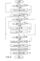
- control circuit 76a An operation state of the control circuit 76a will be described with reference to a flowchart shown in FIG. 5.
- the following effect is obtained by the endoscopic lithotripsy apparatus 75 according to the embodiment.
- the description of the same effect as that described with respect to the lithotripsy probe apparatus 10 of the first embodiment will be omitted.
- the ON/OFF of the contacts 82 is defined by the positions of the marks ⁇ , ⁇ of the outer case 26 with respect to the mark 70 of the cover member 28. Therefore, the contacts 82 can be allowed to function as a position detection mechanism which detects the positions of the marks ⁇ , ⁇ with respect to the mark 70, that is, which detects the position of the cover member 28 capable of generating the ultrasonic vibration and the mechanical shock force.
- the contacts can also function as a detection mechanism which detects the detached state and closely attached state of the distal end surface 40a of the horn 40 with respect to the inner surface 62a of the coupling member 62. Since the contacts 82 can be switched to ON/OFF, the ON/OFF of the suction pump 77 can accordingly automatically be switched.
- the suction pump 77 does not operate except that the pump is forcibly operated so as to operate the pump switch 81b. Therefore, clogging by the large calculus, and the like stuck into the through hole 41 can be prevented.
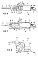
- FIG. 6 shows a schematic sectional view of a hand piece (lithotripsy probe apparatus) 90 in the endoscopic lithotripsy apparatus of the third embodiment.
- FIG. 6 is a sectional view of only a central part of the description of the constitution.
- the hand piece 90 includes an ultrasonic vibration source 91, mechanical shock generation source 92, and crushing probe (insertion portion) 93, for example, of a metal material.
- the crushing probe 93 has a pipe shape.
- a handle attaching portion 93a to which a handle 93b is attached is disposed on the outer peripheral surface of the crushing probe 93.
- the ultrasonic vibration source 91 is covered with a cover.
- a hole (not shown) is disposed along the central axis of the ultrasonic vibration source 91.
- the mechanical shock generation source 92 includes a ultrasonic vibration source fixing mechanism which is capable of fixing the ultrasonic vibration source 91. Therefore, the ultrasonic vibration source 91 can be fixed to the mechanical shock generation source 92.
- a male screw portion 91a is disposed as the ultrasonic vibration source fixing mechanism on the distal end of the cover of the ultrasonic vibration source 91.
- a female screw portion 92a is disposed on the proximal end of the mechanical shock generation source 92. Therefore, since the screw portions 91a, 92a are screwed onto each other, the ultrasonic vibration source 91 is fixed to the mechanical shock generation source 92.
- An ultrasonic vibration source cap 91b is disposed on the distal end of the ultrasonic vibration source 91.
- a female screw portion 91c is disposed on the inner peripheral surface of the cap 91b.
- a crushing probe cap 93c is disposed on the proximal end of the crushing probe 93.
- a male screw portion 93d is disposed on the outer peripheral surface of the cap 93c. Therefore, the ultrasonic vibration source 91 can mutually be screwed onto the crushing probe 93 by the screw portions 91c, 93d.
- the handle 93b attached to the handle attaching portion 93a disposed on the crushing probe 93 is used.
- the handle 93b and the caps 91b, 93c function as the adjustment mechanism which adjusts the attached/detached state between the proximal end of the crushing probe 93 and the male screw portion 91a of the ultrasonic vibration source 91. Therefore, the ultrasonic vibration is transmitted in the closely attached state. The mechanical shock force is transmitted in the detached state. Then, the screw portions 91c, 93d function as the switch mechanism of the ultrasonic vibration source and mechanical shock generation source.
- a driving cable for ultrasonic crushing 94 connected to the ultrasonic vibration source 91 is connected to the ultrasonic driving circuit 76b (see FIG. 4).
- a driving cable for mechanical shock crushing 95 connected to the mechanical shock generation source 92 is connected to the mechanical shock driving circuit 76c (see FIG. 4).
- a cap 96 disposed on the rear end of the ultrasonic vibration source 91 is connected to the suction pump 77 (see FIG. 4) via a suction tube 96a.
- a conductive coil 97 is disposed in the mechanical shock generation source 92. Therefore, when the output from the ultrasonic driving circuit 76b and that from the mechanical shock driving circuit 76c are switched, the ultrasonic vibration and mechanical shock force are transmitted toward a distal end 93e from the proximal end of the probe 93.
- An elastic member 98 is disposed on the distal end of an inner peripheral portion of the coil 97 to fulfill a function of limiting an operation range of the crushing probe 93 and returning the crushing probe 93 to an original position after generation of the shock force.
- the handle 93b is grasped to detach the crushing probe 93 from the cap 91b of the ultrasonic vibration source 91. Then, the probe 93 is slidable in a length direction (axial direction) inside the mechanical shock generation source 92.
- a driving power for generating the mechanical shock is supplied to the mechanical shock generation source 92 via the driving cable for mechanical shock crushing 95.
- a current flows through the coil 97 of the mechanical shock generation source 92, a changing electromagnetic force is used to move the crushing probe 93. The shock by this movement is transmitted to the calculus from the distal end 93e of the crushing probe 93 to break the calculus.
- the crushing probe cap 93c abuts on (collides with) the elastic member 98, and the crushing probe 93 is returned to the original position by an elastic reaction force at this time.
- the current is passed through the coil 97 in a direction opposite to the above-described direction, the crushing probe 93 is pulled rearwards and returned to the original position.
- the handle 93b is held and caps 91b, 93c are used to firmly fix the crushing probe 93 and ultrasonic vibration source 91.
- a high-frequency current is supplied to the ultrasonic vibration source 91 via the driving cable for ultrasonic crushing 94 to generate the ultrasonic vibration.
- the ultrasonic vibration generated by the ultrasonic vibration source 91 is transmitted to the crushing probe 93 via both the caps 91b, 93c.
- the distal end 93e of the crushing probe 93 is ultrasonically driven, and the vibration is used to crush the calculus in contact with the distal end 93e of the crushing probe 93.
- the crushed calculus is sucked from an inner cavity of the distal end 93e of the crushing probe 93 using a suction force of the suction pump 77, and recovered through the cap 96 and suction tube 96a via the inner cavities of the crushing probe 93 and ultrasonic vibration source 91.
- the hand piece 90 of the endoscopic lithotripsy apparatus obtains the following effect.
- the crushing probe 93 When the handle 93b is rotated/operated around the axis of the crushing probe 93, the crushing probe 93 may be fixed to the ultrasonic vibration source 91, or the crushing probe 93 may be detached from the ultrasonic vibration source 91 and may freely be moved in the length direction (axial direction). Therefore, the ultrasonic vibration and mechanical shock force can appropriately be switched to transmit the respective forces to a pipe which is the crushing probe 93.
- the crushing probe 93 when the large calculus is assumed as the crushing object, first the mechanical shock force is transmitted to the calculus via the crushing probe 93 to crush the calculus. Next, the ultrasonic vibration is transmitted to the crushed calculus via the crushing probe 93 to further finely crush the calculus, while the suction force of the suction pump 77 is used to suck/remove the calculus. Therefore, when the solid matters are crushed into small pieces, the crushing probe 93 does not have to be replaced, and therefore the time required for the crushing can be reduced.
- FIG. 7 shows a schematically partial sectional view of the hand piece (lithotripsy probe apparatus) 90 in the endoscopic lithotripsy apparatus of the fourth embodiment.
- the hand piece 90 includes the ultrasonic vibration source 91, mechanical shock generation source 92, and crushing probe 93.
- the mechanical shock generation source 92 includes an ultrasonic vibration source temporary fixing mechanism to temporarily fix the ultrasonic vibration source 91.
- the crushing probe 93 includes a flange 99 projecting outwards in a diametric direction with respect to the axial direction of the crushing probe 93.
- the crushing probe 93 has a pipe shape.
- a protrusion (convex portion) for temporary fixing 92b is disposed on the proximal end of the mechanical shock generation source 92.
- the protrusion 92b projects inwards in the diametric direction.
- a dent (concave portion) for the temporary fixing 91d is disposed on the proximal end of the ultrasonic vibration source 91. This dent 91d is disposed in a circumferential shape.
- the ultrasonic vibration source 91 is temporarily fixed to the mechanical shock generation source 92, when the protrusion (convex portion) 92b disposed on the proximal end of the mechanical shock generation source 92 is mutually fitted in the dent (concave portion) 91d disposed in the proximal end of the ultrasonic vibration source 91. Therefore, the protrusion 92b and dent 91d function as the switch mechanism which switches the ultrasonic vibration and mechanical shock with respect to a treatment object.
- the ultrasonic vibration source 91 can be screwed/fixed onto the crushing probe 93 by the ultrasonic vibration source cap 91b and crushing probe cap 93c.
- the screw portions 91c, 93d are attached/detached using tools such as a wrench (not shown).
- the driving cable for ultrasonic crushing 94 connected to the ultrasonic vibration source 91 is connected to the ultrasonic driving circuit 76b (see FIG. 4).
- the driving cable for mechanical shock crushing 95 connected to the mechanical shock generation source 92 is connected to the mechanical shock driving circuit 76c (see FIG. 4).
- the cap 96 disposed on the rear end of the ultrasonic vibration source 91 is connected to the suction pump 77 via the suction tube 96a.
- the ultrasonic vibration source 91 is further slightly pressed into the mechanical shock generation source 92 (forwards) with respect to the mechanical shock generation source 92 from a state in which the protrusion for the temporary fixing 92b is engaged with the dent for the temporary fixing 91d, and the protrusion 92b is disengaged from the dent 91d.
- the protrusion 92b is disposed on the rear end of the ultrasonic vibration source 91 including the dent 91d.
- the driving current for generating the mechanical shock is supplied to the coil 97 of the mechanical shock generation source 92 via the driving cable for mechanical shock crushing 95.
- the crushing probe 93 integrated with the ultrasonic vibration source 91 moves forwards by the electromagnetic force generated by the change of the magnetic field in the coil 97.
- the shock by this movement is transmitted to the calculus from the distal end 93e of the crushing probe 93 to break the calculus.
- the elastic member 98 abuts on the flange 99 of the crushing probe 93 to perform a function of limiting the operation range and returning the probe to the original position after the generation of the shock force.
- the protrusion for the temporary fixing 92b is engaged with the dent for the temporary fixing 91d to temporarily fix the ultrasonic vibration source 91 to the mechanical shock generation source 92.
- the high-frequency current is supplied to the ultrasonic vibration source 91 via the driving cable for the ultrasonic crushing 94 to generate the ultrasonic vibration.
- the ultrasonic vibration generated by the ultrasonic vibration source 91 is transmitted to the crushing probe 93 via both the caps 91b, 93c.
- the distal end 93e of the crushing probe 93 is ultrasonically vibrated, and the vibration is used to crush the calculus in contact with the distal end 93e of the crushing probe 93.
- the movement of the flange 99 disposed on the crushing probe 93 is not limited by the elastic member 98, and the flange can move in accordance with the movement of the crushing probe 93.
- the crushed calculus is passed through the inner hole of the distal end 93e of the crushing probe 93 using the suction force of the suction pump 77, and recovered through the cap 96 and suction tube 96a via the inner hole of the crushing probe 93 and ultrasonic vibration source 91.
- the hand piece 90 of the endoscopic lithotripsy apparatus obtains the following effect. It is to be noted that the same effect as that of the third embodiment will be omitted.
- the engaged/non-engaged state between the protrusion for temporary fixing 92b and the dent for temporary fixing 91d is switched. Accordingly, the crushing system by the ultrasonic vibration and that by the mechanical shock force can be switched. Therefore, since the crushing probe 93 does not have to be replaced, the time required for the crushing treatment can be reduced.
- FIG. 8 shows a whole lithotripsy system 110.
- FIG. 9 shows a section of a lithotripsy probe apparatus 112.
- the lithotripsy system 110 includes the lithotripsy probe apparatus 112, a suction tube 114, and a power supply main body 116.
- the power supply main body 116 includes a suction pump 116a, a connector 116b, and an operation panel 116c. The end of the suction tube 114 is connected to the suction pump 116a.
- the lithotripsy probe apparatus 112 includes a grasp portion 122, probe (insertion portion) 123, and power supply cord 124.
- the power supply cord 124 extends from the rear end of the grasp portion 122, and includes a connection portion 124a connected to the connector 116b of the power supply main body 116.
- the probe 123 is disposed on the distal end of the grasp portion 122.
- the probe 123 includes a pipe 132 including a screw portion 133 on the proximal end.
- a through hole 134 is formed in a coaxial center of the pipe 132 and screw portion 133.
- the distal end of a horn 171 of the grasp portion 122 described later is screwed/fastened and detachably attached to the proximal end of the probe 123 via the screw portion 133.
- the grasp portion 122 includes a cylindrical outer portion 135.
- a flange portion 135a projecting in a central axis direction of the outer portion 135 is disposed on the distal end of the outer portion 135.
- a male screw portion 135b is formed on the outer peripheral surface of the distal end of the outer portion 135.
- a substantially cylindrical outer case 137 including a female screw portion 137a on the inner peripheral surface of the proximal end is screwed onto the male screw portion 135b.
- the outer peripheral surface of the outer portion 135 is on the same plane as that of the outer peripheral surface of the outer case 137.
- a flange portion 137b projecting toward the central axis direction of the outer case 137 is disposed on the distal end of the outer case 137.
- One end of a screw 180 described later is disposed on the flange portion 137b.
- a female screw portion 135c is formed on the inner peripheral surface of the rear end of the outer portion 135.
- a substantially cylindrical outer case 141 including a male screw portion 141a on the outer peripheral surface of the distal end is screwed onto the female screw portion 135c.
- the inner peripheral surface of the outer portion 135 is on the same plane as that of the outer peripheral surface of the outer case 141.
- a cap 143, a support portion 144, a hole for lead 145 of a lead wire 166 described later, and a hole for lead 146 of a lead wire 148a described later are integrally disposed.
- the cap 143 is formed in a cylindrical shape, and disposed on the central axis of the outer portion 135 and outer case 141.
- One end of the suction tube 114 is connected to the proximal end of the cap 143.
- the other end of the suction tube 114 is connected to the suction pump 116a.
- An O-ring 174 described later is disposed on the inner peripheral surface of the distal end of the cap 143 (inside the outer portion 135) to achieve the watertightness with a cylindrical bolt portion 172 described later.
- the support portion 144 is formed in the cylindrical shape, and is disposed on the central axis of the outer portion 135 and outer case 141. The distal end of the support portion 144 abuts on the flange portion 135a of the distal end of the outer portion 135. At this time, a coil 148 which is the mechanical shock generation source and a metal coat film 149 are disposed in a space between the support portion 144 and the inner peripheral surface of the outer portion 135. The outer peripheral surface of the support portion 144 is coated with the metal coat film 149. That is, the coil 148 and metal coat film 149 are supported on the outer periphery of the support portion 144. The coil 148 and metal coat film 149 are attached to one end of the lead wire 148a whose other end is connected to the power supply main body 116 (see FIG. 8), and the wire extends rearwards.
- a Langevin type ultrasonic vibrator 150 is contained as the ultrasonic vibration source inside the support portion 144.
- the outer peripheral surface of the ultrasonic vibrator 150 is disposed apart from the inner peripheral surface of the support portion 144.
- the ultrasonic vibrator 150 includes a piezoelectric device 152, first and second electrode plates 154, 156, and metal blocks 158, 160.
- the piezoelectric device 152, first electrode plate 154, and metal blocks 158, 160 are formed in annular shapes.
- the second electrode plate 156 is formed as a cylindrical bolt.
- a device support portion 156a for supporting the piezoelectric device 152 is disposed on the proximal end of the second electrode plate 156.
- the second electrode plate 156 is passed through the inner hole of the piezoelectric device 152, first electrode plate 154, and metal blocks 158, 160.
- a male screw portion 156b is disposed on the distal end of the second electrode plate 156.
- the male screw portion 156b is screwed onto a female screw portion 158a of the metal block 158.
- the second electrode plate 156 includes disc-shaped protrusions disposed every other piezoelectric device 152.
- a plurality of piezoelectric devices 152 is disposed on the rear end of the front-side metal block 158.
- the first and second electrode plates 154, 156 are alternately disposed between the piezoelectric devices 152.
- the piezoelectric device 152 disposed on a rearmost side abuts on the device support portion 156a of the rear end of the second electrode plate 156.
- the device support portion 156a abuts on the rear-side metal block 160.
- the piezoelectric device 152 is firmly held between the front-side metal block 158 and the device support portion 156a.
- a male screw portion 160a screwed onto a female screw portion 141b of the inner peripheral surface of the outer case 141 is disposed on the outer peripheral surface of the rear-side metal block 160. Therefore, the Langevin type ultrasonic vibrator 150 is held in the outer case 141.
- the electrode plates 154, 156 are connected to one end of the lead wire 166 whose other end is connected to the power supply main body 116 (see FIG. 8) and which extends rearwards.
- a substantially conical oscillation section 170 is disposed on the distal end of the ultrasonic vibrator 150. That is, the oscillation section 170 abuts on the distal end of the metal block 158.
- the oscillation section 170 includes the horn 171 and bolt portion 172.
- the horn 171 is formed substantially in the conical shape including an opening along the central axis.
- the screw portion 133 onto which the proximal end of the pipe 132 of the probe 123 is screwed is disposed on the distal end of the horn 171.
- a female screw portion 171a is formed on the proximal end of the horn 171.
- the bolt portion 172 has a cylindrical shape and includes a male screw portion 172a on the outer peripheral surface of the distal end.
- the male screw portion 172a of the bolt portion 172 is screwed onto the female screw portion 171a of the proximal end of the horn 171 in a passed state inside the second electrode plate 156 (ultrasonic vibrator 150).
- the O-ring 174 is disposed on the outer peripheral surface of the proximal end of the bolt portion 172 between the bolt portion and the inner peripheral surface of the cap 143. Therefore, the solution or the crushed solid matter is prevented from entering the ultrasonic vibrator 150, metal block 160 here, and the block is supported in a watertight manner.
- a flange portion 175 projecting outwards in the diametric direction is integrally formed on the proximal end of the horn 171.
- An O-ring receiving portion 177 in which an O-ring 176 is disposed is disposed in the outer peripheral surface of the flange portion 175.
- the O-ring 176 abuts on the inner peripheral surface of the outer case 137 on the distal end side.
- a spring 180 is disposed as an elastic material which urges the flange portion 175 on the rear side of the outer case 137 between the flange portion 175 and the flange portion 137b of the outer case 137.
- One end of the spring 180 is supported by the flange portion 137b of the outer case 137 as described above.
- the other end of the spring 180 is supported by the flange portion 175. Therefore, the oscillation section 170 is slidable along a slide surface 137c which is the inner peripheral surface of the outer case 137 against the urging force of the spring 180 along the axial direction of the probe 123 in the outer case 137.
- the shock transmitted to both the horn 171 and the outer case 137 is absorbed by the O-ring 176 and spring 180.
- An annular permanent magnet 182 is disposed between the flange portion 175 and the flange portion 135a projecting in the central axis direction of the outer portion 135.
- the flange portion 175 abuts on the permanent magnet 182 from the rear end.
- the permanent magnet 182 is held between the flange portion 175 and the distal end of the outer portion 135.
- the permanent magnet 182, and the coil 148 and metal coat film 149 magnetized at the time of the supply of the current function as the adjustment mechanism capable of adjusting the attached/detached state including an abutment (closely attached) state in which the oscillation section 170 is attracted by the Langevin type ultrasonic vibrator 150 that is the ultrasonic vibration source, and a repelled and detached state.
- the coil 148 and metal coat film 149 repeat the state in which the magnets are attracted by each other to abut on each other and the repelled and detached state by continuous switch of the direction of the current passed through the coil 148 and metal coat film 149, and therefore functions as the mechanical shock generation source.
- the ultrasonic vibration and mechanical shock force transmitted to the probe 123 are switched, and therefore the power supply main body 116 functions as the switch mechanism of the force transmitted to the probe 123.
- the lead wire 166 is connected to the electrode plates 154, 156 and guided outside the lithotripsy probe apparatus 112 via the hole for lead 145.
- the lead wire 148a is connected to the coil 148 and guided outside the lithotripsy probe apparatus 112 via the hole for lead 146.
- the holes for lead 145, 146 are disposed adjacent to each other.
- a break preventive member 185 is disposed to cover the lead wire 148a electrically connected to the coil 148 and the lead wire 166 connected to the electrode plate 154 and to prevent disconnection.
- the probe 123 is fastened to the distal end of the oscillation section 170 of the grasp portion 122 using the screw portion 133 to form the lithotripsy probe apparatus 112.
- the connection portion 124a of the lithotripsy probe apparatus 112 is connected to the power supply main body 116.
- One end of the suction tube 114 is pressed into the cap for suction 143, and the other end of the tube is meshed with the suction pump 116a and guided into an excrement container (not shown).
- the power supply main body 116 is turned on to set the power supply main body 116 with the operation panel 116c. Switches (not shown) are operated to start output.
- the power is supplied to the lithotripsy probe apparatus 112 from the power supply main body 116 through the connection portion 124a and power supply cord 124 in accordance with the setting of the operation panel 116c.
- the break preventive member 185 prevents the disconnection by the two-core lead wires 166, 148a in the power supply cord 124, and the power is transmitted to the inside of the grasp portion 122 through the holes for lead 145, 146.
- the setting of the operation panel 116c has specifications in which a mechanical vibration generation state and ultrasonic vibration generation state are selectable. First, the ultrasonic vibration generation state will be described.
- the current is passed through the coil 148 and metal coat film 149 from the power supply main body 116 set to the ultrasonic vibration generation state via the lead wire 148a.
- the coil 148 and metal coat film 149 change the magnetic field and transforms the coil 148 into an electromagnet.
- the permanent magnet 182 and coil 148 attract each other. Therefore, the closely attached state is obtained in which the horn 171 of the oscillation section 170 is firmly pressed onto the metal block 158, that is, Langevin type ultrasonic vibrator 150.
- the current is passed through the electrode plate 154 via the lead wire 166.
- the ultrasonic vibration is generated in the piezoelectric device 152, the vibration is transmitted to the oscillation section 170 firmly pressed through the metal block 158, the amplitude is enlarged by the horn 171, and the ultrasonic vibration is transmitted to the distal end of the probe 123 through the screw portion 133 and pipe 132.
- the solid matters such as the calculus in the body cavity is crushed/treated by this ultrasonic vibration.
- the ultrasonic vibration generation state of the power supply main body 116 is switched so as to set the mechanical vibration generation state.
- the current is passed through the coil 148 and metal coat film 149 via the lead wire 148a from the power supply main body 116 set to the mechanical vibration generation state.
- the magnetic field changes by the coil 148 and metal coat film 149, and the coil 148 is transformed into the electromagnet.
- the current is stopped in a pulse manner, or the flow direction of the current is reversed. Accordingly, the repelled and detached state with respect to the permanent magnet 182, and the state (or the attracted abutment state) in which the magnetic force is not produced are repeatedly generated.
- the oscillation section 170 slides forwards along the outer case 137, and projects with a great force with respect to the grasp portion 122.
- the current direction is reversed, and the magnetic force is exerted in an attracted state. Or, the current is stopped to the coil 148, and the coil 148 is not-magnetized state.
- the urging the flange portion 175 of the spring 180 rearwards is used to return the oscillation section 170 to the grasp portion 122. This is continuously generated to realize the mechanical vibration generation state.
- the solid matters such as the calculus in the body cavity are broken/treated by this mechanical vibration.
- Residues generated as a result of the lithotripsy treatment of the solid matters such as the calculus performed using the mechanical or ultrasonic vibration are discharged through the through hole 134 formed by the pipe 132, horn 171, bolt portion 172, and cap 143 via the suction tube 114 by the operation of the suction pump 116a of the power supply main body 116. It is to be noted that this discharge may be performed while generating the mechanical or ultrasonic vibration.
- the lithotripsy system 110 obtains the following effect.
- the breaking by the mechanical vibration (mechanical shock force) and the crushing by the ultrasonic vibration can easily be switched by the current passed from the power supply main body 116 to efficiently use both, and it is possible to crush/suck/remove the calculus.
- the equivalent operation is performed in the related art, two lithotripsy treatment apparatuses have heretofore been required, but in the present invention, the operation can be done with one apparatus, and therefore a replacing operation during the operation is not required. Therefore, operability can be enhanced, and a surgical operation time can be reduced.
Landscapes
- Health & Medical Sciences (AREA)
- Surgery (AREA)
- Engineering & Computer Science (AREA)
- Life Sciences & Earth Sciences (AREA)
- Biomedical Technology (AREA)
- Molecular Biology (AREA)
- Vascular Medicine (AREA)
- Orthopedic Medicine & Surgery (AREA)
- Mechanical Engineering (AREA)
- Heart & Thoracic Surgery (AREA)
- Medical Informatics (AREA)
- Nuclear Medicine, Radiotherapy & Molecular Imaging (AREA)
- Animal Behavior & Ethology (AREA)
- General Health & Medical Sciences (AREA)
- Public Health (AREA)
- Veterinary Medicine (AREA)
- Surgical Instruments (AREA)
- Ultra Sonic Daignosis Equipment (AREA)
Applications Claiming Priority (2)
| Application Number | Priority Date | Filing Date | Title |
|---|---|---|---|
| JP2002352702A JP2004180997A (ja) | 2002-12-04 | 2002-12-04 | 内視鏡下砕石装置 |
| JP2002352702 | 2002-12-04 |
Publications (3)
| Publication Number | Publication Date |
|---|---|
| EP1426014A2 true EP1426014A2 (fr) | 2004-06-09 |
| EP1426014A3 EP1426014A3 (fr) | 2006-06-28 |
| EP1426014B1 EP1426014B1 (fr) | 2010-06-16 |
Family
ID=32310723
Family Applications (1)
| Application Number | Title | Priority Date | Filing Date |
|---|---|---|---|
| EP03027819A Expired - Lifetime EP1426014B1 (fr) | 2002-12-04 | 2003-12-03 | Appareil endoscopique de lithotritie |
Country Status (4)
| Country | Link |
|---|---|
| US (1) | US7645245B2 (fr) |
| EP (1) | EP1426014B1 (fr) |
| JP (1) | JP2004180997A (fr) |
| DE (1) | DE60332988D1 (fr) |
Cited By (5)
| Publication number | Priority date | Publication date | Assignee | Title |
|---|---|---|---|---|
| EP1719466A4 (fr) * | 2004-02-23 | 2012-08-22 | Olympus Corp | Lithotripteur |
| CN104027221A (zh) * | 2014-07-01 | 2014-09-10 | 朱清华 | 体位理疗排石装置 |
| WO2018013629A1 (fr) * | 2016-07-12 | 2018-01-18 | Ethicon Llc | Instrument chirurgical ultrasonore à transducteur piézoélectrique à lumière centrale |
| EP3318204A1 (fr) * | 2016-11-08 | 2018-05-09 | Enraf Nonius B.V. | Générateur d'ondes de choc |
| US10660660B2 (en) | 2014-12-26 | 2020-05-26 | Olympus Corporation | Detector-equipped treatment tool |
Families Citing this family (41)
| Publication number | Priority date | Publication date | Assignee | Title |
|---|---|---|---|---|
| JP2005040222A (ja) * | 2003-07-24 | 2005-02-17 | Olympus Corp | 超音波処置装置 |
| US8182501B2 (en) | 2004-02-27 | 2012-05-22 | Ethicon Endo-Surgery, Inc. | Ultrasonic surgical shears and method for sealing a blood vessel using same |
| EP3162309B1 (fr) | 2004-10-08 | 2022-10-26 | Ethicon LLC | Instrument chirurgical ultrasonique |
| US20070191713A1 (en) | 2005-10-14 | 2007-08-16 | Eichmann Stephen E | Ultrasonic device for cutting and coagulating |
| US7621930B2 (en) | 2006-01-20 | 2009-11-24 | Ethicon Endo-Surgery, Inc. | Ultrasound medical instrument having a medical ultrasonic blade |
| US7942809B2 (en) * | 2006-05-26 | 2011-05-17 | Leban Stanley G | Flexible ultrasonic wire in an endoscope delivery system |
| US8142461B2 (en) | 2007-03-22 | 2012-03-27 | Ethicon Endo-Surgery, Inc. | Surgical instruments |
| US8911460B2 (en) | 2007-03-22 | 2014-12-16 | Ethicon Endo-Surgery, Inc. | Ultrasonic surgical instruments |
| US8057498B2 (en) | 2007-11-30 | 2011-11-15 | Ethicon Endo-Surgery, Inc. | Ultrasonic surgical instrument blades |
| US8523889B2 (en) | 2007-07-27 | 2013-09-03 | Ethicon Endo-Surgery, Inc. | Ultrasonic end effectors with increased active length |
| US8808319B2 (en) | 2007-07-27 | 2014-08-19 | Ethicon Endo-Surgery, Inc. | Surgical instruments |
| US8512365B2 (en) | 2007-07-31 | 2013-08-20 | Ethicon Endo-Surgery, Inc. | Surgical instruments |
| US8430898B2 (en) | 2007-07-31 | 2013-04-30 | Ethicon Endo-Surgery, Inc. | Ultrasonic surgical instruments |
| US9044261B2 (en) | 2007-07-31 | 2015-06-02 | Ethicon Endo-Surgery, Inc. | Temperature controlled ultrasonic surgical instruments |
| AU2008308606B2 (en) | 2007-10-05 | 2014-12-18 | Ethicon Endo-Surgery, Inc. | Ergonomic surgical instruments |
| US10010339B2 (en) | 2007-11-30 | 2018-07-03 | Ethicon Llc | Ultrasonic surgical blades |
| US9700339B2 (en) | 2009-05-20 | 2017-07-11 | Ethicon Endo-Surgery, Inc. | Coupling arrangements and methods for attaching tools to ultrasonic surgical instruments |
| US8486096B2 (en) | 2010-02-11 | 2013-07-16 | Ethicon Endo-Surgery, Inc. | Dual purpose surgical instrument for cutting and coagulating tissue |
| US8951272B2 (en) | 2010-02-11 | 2015-02-10 | Ethicon Endo-Surgery, Inc. | Seal arrangements for ultrasonically powered surgical instruments |
| JP5385485B2 (ja) * | 2011-06-20 | 2014-01-08 | オリンパスメディカルシステムズ株式会社 | 超音波処置装置及びプローブユニット |
| JP5253693B1 (ja) * | 2011-12-08 | 2013-07-31 | オリンパスメディカルシステムズ株式会社 | 超音波プローブ |
| US9820768B2 (en) | 2012-06-29 | 2017-11-21 | Ethicon Llc | Ultrasonic surgical instruments with control mechanisms |
| US10226273B2 (en) | 2013-03-14 | 2019-03-12 | Ethicon Llc | Mechanical fasteners for use with surgical energy devices |
| US9360124B2 (en) | 2013-03-15 | 2016-06-07 | Cook Medical Technologies Llc | Bi-directional valve device for selective control of fluid flow through multiple converging paths |
| JP5782064B2 (ja) * | 2013-04-15 | 2015-09-24 | 富士フイルム株式会社 | 内視鏡システム |
| GB2521229A (en) | 2013-12-16 | 2015-06-17 | Ethicon Endo Surgery Inc | Medical device |
| AU2015343272B2 (en) | 2014-11-03 | 2020-07-16 | Cagent Vascular, Inc. | Serration balloon |
| US11020140B2 (en) | 2015-06-17 | 2021-06-01 | Cilag Gmbh International | Ultrasonic surgical blade for use with ultrasonic surgical instruments |
| US10357303B2 (en) | 2015-06-30 | 2019-07-23 | Ethicon Llc | Translatable outer tube for sealing using shielded lap chole dissector |
| US10893883B2 (en) | 2016-07-13 | 2021-01-19 | Ethicon Llc | Ultrasonic assembly for use with ultrasonic surgical instruments |
| US10842522B2 (en) | 2016-07-15 | 2020-11-24 | Ethicon Llc | Ultrasonic surgical instruments having offset blades |
| US10285723B2 (en) | 2016-08-09 | 2019-05-14 | Ethicon Llc | Ultrasonic surgical blade with improved heel portion |
| USD847990S1 (en) | 2016-08-16 | 2019-05-07 | Ethicon Llc | Surgical instrument |
| US10952759B2 (en) | 2016-08-25 | 2021-03-23 | Ethicon Llc | Tissue loading of a surgical instrument |
| US10736649B2 (en) | 2016-08-25 | 2020-08-11 | Ethicon Llc | Electrical and thermal connections for ultrasonic transducer |
| US10603064B2 (en) | 2016-11-28 | 2020-03-31 | Ethicon Llc | Ultrasonic transducer |
| US10820920B2 (en) | 2017-07-05 | 2020-11-03 | Ethicon Llc | Reusable ultrasonic medical devices and methods of their use |
| DE202018006201U1 (de) * | 2018-01-19 | 2019-07-19 | Ferton Holding S.A. | System zum Zertrümmern und/oder Entfernen von Körpersteinen und Adapterelement |
| DE102018101215B4 (de) * | 2018-01-19 | 2023-09-07 | Ferton Holding S.A. | Vorrichtung zur Zertrümmerung eines Körpersteins |
| DE102020117713B4 (de) | 2020-07-06 | 2024-11-07 | Karl Storz Se & Co. Kg | Lithotripsievorrichtung und Verfahren zum Betrieb einer Lithotripsievorrichtung |
| GB2628084B (en) * | 2023-03-07 | 2025-06-11 | De Soutter Medical Ltd | Orthopaedic impactor |
Citations (1)
| Publication number | Priority date | Publication date | Assignee | Title |
|---|---|---|---|---|
| US20020010478A1 (en) | 2000-06-15 | 2002-01-24 | Ferton Holding S.A. | Device for removal of calculi |
Family Cites Families (28)
| Publication number | Priority date | Publication date | Assignee | Title |
|---|---|---|---|---|
| DE3119295A1 (de) * | 1981-05-14 | 1982-12-16 | Siemens AG, 1000 Berlin und 8000 München | Einrichtung zum zerstoeren von konkrementen in koerperhoehlen |
| US4660573A (en) | 1985-05-08 | 1987-04-28 | Fibra-Sonics, Inc. | Ultrasonic lithotriptor probe |
| US4922902A (en) * | 1986-05-19 | 1990-05-08 | Valleylab, Inc. | Method for removing cellular material with endoscopic ultrasonic aspirator |
| US4989588A (en) * | 1986-03-10 | 1991-02-05 | Olympus Optical Co., Ltd. | Medical treatment device utilizing ultrasonic wave |
| US4861332A (en) * | 1986-04-14 | 1989-08-29 | Ultramed Corporation | Ultrasonic probe |
| US4867141A (en) * | 1986-06-18 | 1989-09-19 | Olympus Optical Co., Ltd. | Medical treatment apparatus utilizing ultrasonic wave |
| US5065741A (en) * | 1987-04-16 | 1991-11-19 | Olympus Optical Co. Ltd. | Extracoporeal ultrasonic lithotripter with a variable focus |
| US5178135A (en) * | 1987-04-16 | 1993-01-12 | Olympus Optical Co., Ltd. | Therapeutical apparatus of extracorporeal type |
| US5125837A (en) * | 1988-01-06 | 1992-06-30 | Dentsply Management Corp. | Apparatus and method for therapeutic lavage and scaling of teeth |
| JPH01276112A (ja) * | 1988-04-28 | 1989-11-06 | Olympus Optical Co Ltd | 内視鏡 |
| JPH02215452A (ja) * | 1989-02-17 | 1990-08-28 | Toshiba Corp | 結石破砕装置 |
| DE3932966C1 (fr) * | 1989-10-03 | 1991-04-04 | Richard Wolf Gmbh, 7134 Knittlingen, De | |
| US5391144A (en) * | 1990-02-02 | 1995-02-21 | Olympus Optical Co., Ltd. | Ultrasonic treatment apparatus |
| DE4313768C2 (de) * | 1993-04-27 | 2002-07-11 | Walz Elektronik Gmbh | Vorrichtung zur Steinzertrümmerung |
| DE4405656C2 (de) * | 1994-02-22 | 1998-12-10 | Ferton Holding | Einrichtung zum Entfernen von Körpersteinen |
| US5514086A (en) * | 1994-09-22 | 1996-05-07 | Sonique Surgical Systems, Inc. | Multipiece ultrasonic probe for liposuction |
| US6129735A (en) * | 1996-06-21 | 2000-10-10 | Olympus Optical Co., Ltd. | Ultrasonic treatment appliance |
| US6887252B1 (en) * | 1996-06-21 | 2005-05-03 | Olympus Corporation | Ultrasonic treatment appliance |
| DE19718511C5 (de) * | 1997-05-02 | 2010-10-21 | Sanuwave, Inc., | Gerät zur Applikation von akustischen Stoßwellen |
| US6149656A (en) * | 1998-09-11 | 2000-11-21 | Volker Walz | Electrodynamic lithotriptor |
| US6416525B1 (en) * | 1999-06-08 | 2002-07-09 | Olympus Optical Co., Ltd. | Ultrasonic vibrator capable of infallably preventing drops of water from entering the inside of a casing of the vibrator even if autoclave sterilization without a drying process is performed |
| JP3600070B2 (ja) * | 1999-07-02 | 2004-12-08 | オリンパス株式会社 | 超音波処置具 |
| US6695782B2 (en) * | 1999-10-05 | 2004-02-24 | Omnisonics Medical Technologies, Inc. | Ultrasonic probe device with rapid attachment and detachment means |
| US7229455B2 (en) * | 2001-09-03 | 2007-06-12 | Olympus Corporation | Ultrasonic calculus treatment apparatus |
| JP2003299666A (ja) * | 2002-04-09 | 2003-10-21 | Olympus Optical Co Ltd | 超音波処置装置 |
| EP1380265A1 (fr) * | 2002-07-11 | 2004-01-14 | Olympus Optical Corporation Limited | Appareil pour le traitement de calculs |
| JP2005027907A (ja) * | 2003-07-07 | 2005-02-03 | Olympus Corp | 超音波手術システムおよびプローブ |
| US7873405B2 (en) * | 2004-06-02 | 2011-01-18 | Siemens Medical Solutions Usa, Inc. | Automated detection of Alzheimer's disease by statistical analysis with positron emission tomography images |
-
2002
- 2002-12-04 JP JP2002352702A patent/JP2004180997A/ja not_active Withdrawn
-
2003
- 2003-12-03 EP EP03027819A patent/EP1426014B1/fr not_active Expired - Lifetime
- 2003-12-03 DE DE60332988T patent/DE60332988D1/de not_active Expired - Lifetime
- 2003-12-04 US US10/729,074 patent/US7645245B2/en active Active
Patent Citations (1)
| Publication number | Priority date | Publication date | Assignee | Title |
|---|---|---|---|---|
| US20020010478A1 (en) | 2000-06-15 | 2002-01-24 | Ferton Holding S.A. | Device for removal of calculi |
Cited By (6)
| Publication number | Priority date | Publication date | Assignee | Title |
|---|---|---|---|---|
| EP1719466A4 (fr) * | 2004-02-23 | 2012-08-22 | Olympus Corp | Lithotripteur |
| CN104027221A (zh) * | 2014-07-01 | 2014-09-10 | 朱清华 | 体位理疗排石装置 |
| CN104027221B (zh) * | 2014-07-01 | 2015-11-04 | 朱清华 | 体位理疗排石装置 |
| US10660660B2 (en) | 2014-12-26 | 2020-05-26 | Olympus Corporation | Detector-equipped treatment tool |
| WO2018013629A1 (fr) * | 2016-07-12 | 2018-01-18 | Ethicon Llc | Instrument chirurgical ultrasonore à transducteur piézoélectrique à lumière centrale |
| EP3318204A1 (fr) * | 2016-11-08 | 2018-05-09 | Enraf Nonius B.V. | Générateur d'ondes de choc |
Also Published As
| Publication number | Publication date |
|---|---|
| DE60332988D1 (de) | 2010-07-29 |
| US7645245B2 (en) | 2010-01-12 |
| JP2004180997A (ja) | 2004-07-02 |
| US20040138594A1 (en) | 2004-07-15 |
| EP1426014A3 (fr) | 2006-06-28 |
| EP1426014B1 (fr) | 2010-06-16 |
Similar Documents
| Publication | Publication Date | Title |
|---|---|---|
| EP1426014B1 (fr) | Appareil endoscopique de lithotritie | |
| US7122032B2 (en) | Operation system and mounting device for external device for use in the operation system | |
| JP5855146B2 (ja) | イメージング装置 | |
| JP4128496B2 (ja) | 超音波処置装置 | |
| US20040010267A1 (en) | Calculus treatment apparatus | |
| US7449004B2 (en) | Ultrasonic treatment device and ultrasonic treatment system | |
| JP3931051B2 (ja) | 結石除去装置 | |
| US7731677B2 (en) | Ultrasonic surgical system | |
| JP4906978B2 (ja) | 超音波診断システム | |
| CN102176876A (zh) | 手术用处置系统和手术用处置系统的控制方法 | |
| JP2002177295A (ja) | 外科用器具のハンドピース | |
| US20100274269A1 (en) | Single probe with disturber | |
| JPH06304176A (ja) | 縫合結紮装置 | |
| US10178999B2 (en) | Energy treatment unit, energy treatment instrument and energy treatment system | |
| CA2383128A1 (fr) | Instrument chirurgical a ultrasons | |
| JP4245790B2 (ja) | 超音波処置具 | |
| JP2003235862A (ja) | 超音波処置具 | |
| EP1719466B1 (fr) | Lithotripteur | |
| JP2005137481A (ja) | 超音波手術装置 | |
| JPH04357942A (ja) | 超音波手術用ハンドピース | |
| JP2004041503A (ja) | 砕石装置 | |
| JP2004041431A (ja) | 結石処置装置 | |
| JPH09248308A (ja) | 超音波手術装置 | |
| JPH11178832A (ja) | 超音波手術装置 | |
| JP2004141181A (ja) | 振動伝達装置 |
Legal Events
| Date | Code | Title | Description |
|---|---|---|---|
| PUAI | Public reference made under article 153(3) epc to a published international application that has entered the european phase |
Free format text: ORIGINAL CODE: 0009012 |
|
| 17P | Request for examination filed |
Effective date: 20031203 |
|
| AK | Designated contracting states |
Kind code of ref document: A2 Designated state(s): AT BE BG CH CY CZ DE DK EE ES FI FR GB GR HU IE IT LI LU MC NL PT RO SE SI SK TR |
|
| AX | Request for extension of the european patent |
Extension state: AL LT LV MK |
|
| PUAL | Search report despatched |
Free format text: ORIGINAL CODE: 0009013 |
|
| AK | Designated contracting states |
Kind code of ref document: A3 Designated state(s): AT BE BG CH CY CZ DE DK EE ES FI FR GB GR HU IE IT LI LU MC NL PT RO SE SI SK TR |
|
| AX | Request for extension of the european patent |
Extension state: AL LT LV MK |
|
| AKX | Designation fees paid |
Designated state(s): DE FR GB |
|
| 17Q | First examination report despatched |
Effective date: 20090416 |
|
| GRAP | Despatch of communication of intention to grant a patent |
Free format text: ORIGINAL CODE: EPIDOSNIGR1 |
|
| GRAS | Grant fee paid |
Free format text: ORIGINAL CODE: EPIDOSNIGR3 |
|
| GRAA | (expected) grant |
Free format text: ORIGINAL CODE: 0009210 |
|
| AK | Designated contracting states |
Kind code of ref document: B1 Designated state(s): DE FR GB |
|
| REF | Corresponds to: |
Ref document number: 60332988 Country of ref document: DE Date of ref document: 20100729 Kind code of ref document: P |
|
| PGFP | Annual fee paid to national office [announced via postgrant information from national office to epo] |
Ref country code: FR Payment date: 20101224 Year of fee payment: 8 |
|
| PGFP | Annual fee paid to national office [announced via postgrant information from national office to epo] |
Ref country code: GB Payment date: 20101201 Year of fee payment: 8 |
|
| PLBE | No opposition filed within time limit |
Free format text: ORIGINAL CODE: 0009261 |
|
| STAA | Information on the status of an ep patent application or granted ep patent |
Free format text: STATUS: NO OPPOSITION FILED WITHIN TIME LIMIT |
|
| 26N | No opposition filed |
Effective date: 20110317 |
|
| REG | Reference to a national code |
Ref country code: DE Ref legal event code: R097 Ref document number: 60332988 Country of ref document: DE Effective date: 20110316 |
|
| GBPC | Gb: european patent ceased through non-payment of renewal fee |
Effective date: 20111203 |
|
| REG | Reference to a national code |
Ref country code: FR Ref legal event code: ST Effective date: 20120831 |
|
| PG25 | Lapsed in a contracting state [announced via postgrant information from national office to epo] |
Ref country code: GB Free format text: LAPSE BECAUSE OF NON-PAYMENT OF DUE FEES Effective date: 20111203 |
|
| PG25 | Lapsed in a contracting state [announced via postgrant information from national office to epo] |
Ref country code: FR Free format text: LAPSE BECAUSE OF NON-PAYMENT OF DUE FEES Effective date: 20120102 |
|
| PGFP | Annual fee paid to national office [announced via postgrant information from national office to epo] |
Ref country code: DE Payment date: 20181210 Year of fee payment: 16 |
|
| REG | Reference to a national code |
Ref country code: DE Ref legal event code: R119 Ref document number: 60332988 Country of ref document: DE |
|
| PG25 | Lapsed in a contracting state [announced via postgrant information from national office to epo] |
Ref country code: DE Free format text: LAPSE BECAUSE OF NON-PAYMENT OF DUE FEES Effective date: 20200701 |