EP1426312B1 - Convoyeur de triage - Google Patents
Convoyeur de triage Download PDFInfo
- Publication number
- EP1426312B1 EP1426312B1 EP03257557A EP03257557A EP1426312B1 EP 1426312 B1 EP1426312 B1 EP 1426312B1 EP 03257557 A EP03257557 A EP 03257557A EP 03257557 A EP03257557 A EP 03257557A EP 1426312 B1 EP1426312 B1 EP 1426312B1
- Authority
- EP
- European Patent Office
- Prior art keywords
- transporting
- sorting
- link
- conveyor
- travelling
- Prior art date
- Legal status (The legal status is an assumption and is not a legal conclusion. Google has not performed a legal analysis and makes no representation as to the accuracy of the status listed.)
- Expired - Lifetime
Links
- 125000006850 spacer group Chemical group 0.000 claims description 16
- 230000005611 electricity Effects 0.000 description 3
- 238000009434 installation Methods 0.000 description 3
- 238000007796 conventional method Methods 0.000 description 2
- 239000002184 metal Substances 0.000 description 2
- 238000000034 method Methods 0.000 description 2
- 230000005540 biological transmission Effects 0.000 description 1
- 239000000428 dust Substances 0.000 description 1
Images



Classifications
-
- B—PERFORMING OPERATIONS; TRANSPORTING
- B65—CONVEYING; PACKING; STORING; HANDLING THIN OR FILAMENTARY MATERIAL
- B65G—TRANSPORT OR STORAGE DEVICES, e.g. CONVEYORS FOR LOADING OR TIPPING, SHOP CONVEYOR SYSTEMS OR PNEUMATIC TUBE CONVEYORS
- B65G17/00—Conveyors having an endless traction element, e.g. a chain, transmitting movement to a continuous or substantially-continuous load-carrying surface or to a series of individual load-carriers; Endless-chain conveyors in which the chains form the load-carrying surface
- B65G17/30—Details; Auxiliary devices
- B65G17/32—Individual load-carriers
- B65G17/34—Individual load-carriers having flat surfaces, e.g. platforms, grids, forks
- B65G17/345—Individual load-carriers having flat surfaces, e.g. platforms, grids, forks the surfaces being equipped with a conveyor
-
- B—PERFORMING OPERATIONS; TRANSPORTING
- B65—CONVEYING; PACKING; STORING; HANDLING THIN OR FILAMENTARY MATERIAL
- B65G—TRANSPORT OR STORAGE DEVICES, e.g. CONVEYORS FOR LOADING OR TIPPING, SHOP CONVEYOR SYSTEMS OR PNEUMATIC TUBE CONVEYORS
- B65G2207/00—Indexing codes relating to constructional details, configuration and additional features of a handling device, e.g. Conveyors
- B65G2207/18—Crossing conveyors
Definitions
- the present invention relates to a sorting conveyor preferably provided with a plurality of transporting units travelling on a transporting route shaped in a loop, and in the preferred embodiment to a sorting conveyor provided with a cross-sorter which includes a belt capable of being driven in a direction substantially perpendicular to the direction in which the transporting units are conveyed.
- cross-belt sorters in which a large number of transporting units carried on a route shaped in a loop are connected, include an endless belt that is capable of being driven in a direction perpendicular to the travelling direction of the respective transporting units.
- Most transporting units are supported with four wheels, the units travel by the pulling of the link or the chain, and the endless belt for sorting the transporting units are by a motor using a current collector.
- more recently battery-driven operations are performed by accumulating electricity during transportation by using a free roller (for instance, see Japanese Patent Application Laid-Open Publication No. H1-139418).
- those which comprises a power supply apparatus which include a power generator and a accumulator for driving an endless belt for sorting (for instance, see Japanese Patent Application Laid-Open Publication No. H10-35873).
- a chassis member is formed as a T-shape by combining a member of the longitudinal direction at the centre of a transverse member, and there are provided two wheels at both ends of the transverse member to travel.
- the centre position of the transporting unit shifts from the focus point of the travelling wheels at the time of travelling the curved part, which tends to cause noise easily. That is, as shown in Fig. 16 of the accompanying drawings, there are provided travelling wheels 64, 64 at the both ends of a front part transverse member 63 of chassis 62 in transporting unit 61 to travel.
- the position of the travelling wheels of the transporting unit 61 is shifted from the focus point 60 at the semicircular corner part of the travelling path, which prevents smooth travelling.
- the travelling wheels 64, 64 are arranged at the position with deviation from the focus point, in the case when a fixed wheel is utilised as the force in the thrust direction is applied for a long period, and so the wheels are prone to be damaged easily.
- a rotatable caster type wheel is utilised, a bearing will stop moving because of the dust or the like.
- no consideration is given to an adjustment with regard to the elongation of the chassis.
- a similar sorting conveyor is also described in WO-A-00/02802.
- the present invention seeks to provide an improved sorting conveyor.
- the preferred embodiment provides a cross-belt conveyor which is capable of travelling smoothly in the semicircular corner part of the transporting route. Further more, it can provide a sorting conveyor comprising a cross-sorter which can travel in a stable manner without being affected by its installation level in such a manner that the guide wheel and the travelling wheel function as the coaster type guide wheel (i.e. pinching method) so as to make it possible to travel securely, as well as the main part of the cart is formed in a square cylindrical beam in order to have a torsion corresponding link.
- a sorting conveyor in which a plurality of transporting units are connected to travel on a transporting route shaped in a loop and a conveyor for cross-sorting is provided on each transporting unit which is driven at a sorting position
- the transporting unit includes a chassis formed with a beam shaped link and a base fixed to the centre of the upper part of the link in the perpendicular direction, said transporting unit is connected at the front end and the rear end of the beam shaped link, respectively
- said conveyor for cross-sorting is supported at the upper part of the base in such a manner that the cross-sorting conveyor can be driven reversibly in a direction substantially perpendicular to the travelling direction of the transporting unit, and a pair of travelling wheels which are mounted on both ends of the base come into contact with guide rails arranged on both sides of the transporting route, so that while travelling on the curved part of the transporting route, said travelling wheels travel along a circular locus whose centre is a focus point of
- the conveyor for cross-sorting is preferably an endless belt conveyor or a driving roller conveyor.
- a connecting unit for linking the transporting unit is preferably attached to the front and rear ends of the beam shaped link, and the guide wheel is suspended from respective connecting units provided at the ends of the link so as to travel in such a manner in which to contact the centre rail of the centre of the transporting route.
- level guide rails and oblique side rails at both sides of the transporting route, wherein the travelling wheels that are installed adjacent to both sides of the base come into contact with the level guide rails while coaster type guide wheels which are associated with the travelling wheels so as to pinch the guide rail member come into contact with the oblique side rails.
- the connecting unit with the same width as said link may be assembled while inserting a spacer at an end part of the link detachably, and the connecting unit supports a shaft part of the guide wheel guided by the centre rail with a spherical sliding bearing.
- the endless belt transporting unit is supported by two travelling wheels in which the wheels are positioned at the focus point of the centre of semicircular in the curved part, and the link position is determined appropriately. As a result, it can travel without making noise which has been conventionally generated by the deviation of the centre.
- friction driving is employed as a driven system, that is, a generating system in which a generator is rotated directly from the travelling rails through the free roller.
- a counter-measure is provided against the link chain elongation by inserting a spacer at a joint part of the connecting link so that when the length of the connecting link is elongated, such an elongated connecting link can be fixed easily to the prescribed length by removing any arbitrary spacer of link ends. Moreover, by providing a gap plate for supporting two wheels, it is possible to prevent pitching at the time when the transporting unit travels.
- Fig. 1 is a plan view of a sorting conveyor comprising an embodiment of cross-sorter of the present invention.
- Fig. 2 is a front view of Fig. 1.
- a large number of transporting units 1, on which baggage is loaded are connected and delivered along the transporting route shaped in a loop, and then the baggage is discharged to a sorting chute or conveyors 1a, while the conveyor for the cross-sorter comprising transporting units 1 is driven at the sorting position.
- the example of Fig. 1 shows a cross-belt sorter, in which an endless belt conveyor 2 is provided as the conveyor for cross-sorting.
- the transporting unit 1 travels along a circular excursion of the transporting route, whose centre is the focus point 60 at the time when it travels at the curved part.
- each cart 4 is comprised of a link 5 connected to the front end and the rear end of the chassis via a connecting unit 14, and a base (or a cross-member) 6 fixed to the centre of the upper part of the link 5 in a direction perpendicular or to the link (Figs. 4, 5).
- the link 5 is constituted by using a square cylindrical shaped beam so as to withstand the torsion which is generated by the offset load when baggage is loaded onto the transporting unit 1.
- a level guide wheel 8 is suspended from a connecting pin 15 that is penetrated through this unit 14 while installation plates 7 are fixed securely adjacent to both ends of the base 6.
- Brackets 11 are provided with both plates 7 so that travelling wheels 9 and oblique guide wheels 10 are mounted on the plates by using the brackets 11.
- a generator 18 is mounted onto one bracket 11 (right bracket in Fig. 3) in such a manner that the generator is mounted to have the same axis as that of the travelling wheel 9 of the bracket 11. However, the illustration of the generator 18 is omitted in Figs. 4, 5.
- reference numeral 25a denotes a lower board installed within a conveyor frame 19.
- the level guide wheel 8 comes into contact with a guide rail (centre rail) 12 located at the centre of the travelling route.
- the travelling wheels 9 come into contact with level guide rails 13 at both sides of the travelling route.
- the oblique guide wheels 10 come into contact with side rails 13a of the outer side part of the guide rails 13, which are inclined downwardly.
- a coaster type guide wheel is formed in such a manner as to put the guide rail between the travelling wheels 9 and the oblique guide wheels 10 (Fig. 3).
- Fig. 4 is a front view of the endless belt conveyor
- Fig. 5 is a plan view of Fig. 4.
- the endless belt conveyor 2 is located between a driving pulley 21 provided at the conveyor frame 19 and a driven pulley 22 so as to be driven by a drive motor 3.
- a bracket 17 at one lower part of a conveyor frame 19, and the belt drive motor 3 is mounted thereon.
- An electric power supply circuit is secured for the belt drive motor 3 in such a manner that the generator 18 is fixed to the other bracket 11 which is located at the other end of the base, 6 is activated to accumulate electricity according to the rotation of the travelling wheel as described previously.
- the belt drive motor 3 is activated so as to discharge the baggage (illustration is omitted) to a sorting chute while driving the endless belt 2.
- the conveyor frame 19 is placed on the link 6 and is fastened securely with a bolt 33 (Fig. 8).
- gap plates 16 (Figs. 1, 2, 4 to 7) part of which overlap each other at the front end and the rear end of the conveyor frame 19 that is located at the upper part of the connecting unit 14 (Figs. 6, 7).
- Pulleys 21, 22 have a V-groove 23, and there are provided projections (illustration is omitted) adjacent to both right and left ends of the rear surface of a belt 2a to engage the V-groove into the projection so that the meandering of the belt is prevented.
- a slide head 25 also includes the same V-groove 23 as described above.
- the belt driving system is of the friction driving type.
- the generator 18 employs a technique in which the generator 18 is rotated by directly connecting to the travelling guide rail 13 via the travelling wheel 9, that is, a free roller.
- a generator is driven via a timing belt in a conventional manner, at times, there is a risk to damage a timing belt between a wheel and a generator due to the torque at the time when the electric power is generated.
- the preferred embodiments adopt a direct connecting type electric generator system. Thereby, this provides a stable electric power source for the motor (servo motor) 3 without using such a timing belt.
- Fig. 8 is an enlarged sectional view of the connecting unit 14 of the link 5.
- Fig. 9 is an end view of a beam shaped link 5.
- Fig. 10 is a front view of a spacer.
- a spacer 40 is detachably inserted at the end part of a link 5 to be assembled into the connecting unit 14 while the connecting unit 14 supports a shaft part of the level guide wheel 8 with a spherical sliding bearing 37 so that the link 5 bends freely in the right and left direction or upward and downward direction so as to correspond any curvature.
- This connecting unit 14 achieves continuous contacts to the friction drive (Figs. 11, 12) in such a manner that the connecting unit 14 has the same width as the link 5 so that any gaps between the links can be eliminated.
- the connecting part between the links is made to have the same width as the link so that the cause of the noise can be dissolved.
- the link 5 has employed a square cylindrical shape beam to correspond the torsion so that stable travelling can be performed without being affected by its installation level. In addition to this, as is described later with respect to Fig.
- the cross-belt sorter travels with two travelling wheels 9 along the transporting route. With this structure, it travels smoothly without making noise when it moves, especially, along the circular arc in the curved part whose centre is the focus point 60.
- excess spacers 40 for taking up are mounted on a joint part (connecting unit 14) of the link 5. Thereby, it is possible to absorb the elongation of the link 5 in such a manner that the spacer is removed one by one to fasten the link 5 again when the link 5 is elongated.
- Spacers 40 are inserted between the end face of the connecting link and the connecting unit 14 for the countermeasure for the link chain elongation (for instance, when beam pitch is of 1500 mm, spacer width is of 6 mm).
- Fig. 11 is a plan view of a sorting conveyor comprising a roller conveyor instead of a cross-belt on a transporting unit (a travelling truck) according to a second embodiment of the invention.
- Fig. 12 is an enlarged side view of the travelling truck shown in Fig. 11.
- a roller conveyor 20 mounted on the conveyor frame 19 has the same structure as the one shown in Fig. 3. That is, a transmission chain is engaged between a sprocket fixed to an output shaft of the motor 3 which is driven by the power supplied from the generator 18 and a drive sprocket 21a.
- a chain 22c is engaged between the drive sprocket 21a and the driven sprocket 22a in such a manner that the chain 22c is engaged with a sprocket (not shown) provided at the shaft ends of respective rollers 20a of the conveyor 20.
- the respective rollers 20a are then rotated by the forward and/or reverse rotation of the motor 3.
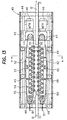
- Fig. 13 is a plan view of a drive unit.
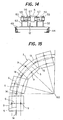
- Fig. 14 is a cross-sectional view cut along line A-A of Fig. 13.
- the drive unit 43 is provided to move the transporting unit 1.
- the drive unit 43 comprises a transverse member 45 for supporting the motor and transverse members 49, 49 for supporting a friction belt on the stand 44 so as to fix a centre rail 12 for guiding the guide wheel 8 to the centre in the longitudinal direction of respective supporting members.
- a pair of motors having reduction gear 46 are arranged on the transverse member 45 in such a manner to pinch the centre rail 12 therebetween.
- a roller supporting member 52 that is put over the transverse members 49 includes friction belts 50 which are pressed down to both side surfaces of the beam shaped link 5 of the cart.
- Each friction belt 50 includes a large number of friction rollers 57 for pressing down the forward side of the friction belt 50 to the tip of the arm 56 is fixed onto the shaft of a torsion spring containing a support cylinder 55 in the direction in which the beam side surface is pressure welded. Further, a guide roller 53 for preventing the bound or shake of the friction belt 50 is provided at the return side of the friction belt 50. Further, take-ups 51 for changing the tension to the friction belts 50 are provided at the side of driven pulleys 48.
- the friction belt is driven while pressing the link side surface so as to eliminate the gap between the friction belts 50 and the link 5 in considering the friction drive.
- Fig. 15 is a plan view showing the focus point on a curved travelling path of the sorting conveyor comprising the cross-sorter according to the present invention.
- the guide wheel 8 is arranged to come into contact with the guide rail (centre rail) 12 located on the centre of the transporting route while being suspended from the connecting unit 14 located at the end of the above described beam shaped link.
- the coaster type travelling wheel 9 and the guide wheel 10 adjacent both ends of the base 6 so as to come into contact with the guide rails 13, 13a located on both sides of the transporting route.
- the travelling wheels travel along a circular excursion whose centre is the focus point 60 of the transporting route.
- the right and left two travelling wheels support the transporting unit in such a manner that the travelling wheels are positioned at the focus point of the semicircular centre in the curved part and the link position is made appropriately, so that the transporting unit can travel the curved part smoothly without occurring noise caused by centre deviation, which is unlikely in the conventional techniques.
- travelling units are supported by the travelling wheels 64 at the both ends of a front part of transverse member 63 (Fig. 16).
- the rail and frame are made of sheet metal so that the accuracy is hardly obtained and noise results.
- the preferred embodiments provide a sorting conveyor in which a large number of connected transporting units travel on a transporting route shaped in the loop configuration, and the respective transporting units include an endless belt capable of being driven in a direction perpendicular to the travelling direction, in which a belt conveyor or a drive roller conveyor can be driven in the direction perpendicular to the travelling direction of the respective transporting units, said belt conveyor or drive roller conveyor is driven in the cross-direction at the sorting position while electricity is supplied by the generator, which enables the smooth sorting work.
- the link may be assembled so as to include a spacer at the connecting part detachably in advance, which makes it possible to adjust the elongation of the link chain easily in such a manner as to attach/detach the spacer to/from the connecting part.
Landscapes
- Engineering & Computer Science (AREA)
- Mechanical Engineering (AREA)
- Discharge Of Articles From Conveyors (AREA)
- Chain Conveyers (AREA)
- Branching, Merging, And Special Transfer Between Conveyors (AREA)
Claims (6)
- Bande de tri incluant une pluralité d'unités de transport (1) raccordées pour déplacer sur un trajet de transport ayant la forme d'une boucle de façon à entraîner un convoyeur afin d'effectuer un double tri (2) sur chaque unité de transport (1), au niveau d'une position de tri (1a), caractérisé en ce que
lesdites unités de transport incluant un châssis constitué avec une pièce de liaison en forme de poutre (5) et une base (6) fixée au centre de la partie supérieure de la pièce de liaison (5) dans une direction sensiblement perpendiculaire, dans laquelle l'unité de transport (1) est raccordée au niveau de l'extrémité avant et l'extrémité arrière de la pièce de liaison en forme de poutre (5), respectivement, et dans laquelle la bande destinée à effectuer un double tri (2) est supportée au niveau de la partie supérieure de la base (6), de telle manière que la bande effectuant un double tri (2) peut être entraînée, inversement, dans une direction sensiblement perpendiculaire à la direction de la translation de l'unité de transport (1) et une paire de galets de translation (9) qui sont montés au niveau des deux extrémités de la base (6) viennent en contact avec des rails de guidage (13), agencés des deux côtés du trajet de transport, de telle sorte que, pendant la translation sur la partie incurvée du trajet de transport, lesdits galets de translation (9) translatent le long d'un lieu sensiblement circulaire, dont le centre est un point de focalisation (60) du trajet de transport incurvé. - Bande de tri selon la revendication 1, dans laquelle ladite bande effectuant un double tri (2) est une bande à toile sans fin.
- Bande de tri selon la revendication 1, dans laquelle ladite bande effectuant un double tri (2) est une bande à rouleau entraîneur.
- Bande de tri selon l'une quelconque des revendications 1 à 3, dans laquelle une unité de raccordement (14) destinée à relier les unités de transport (1) est fixée sur l'extrémité avant et l'extrémité arrière de ladite pièce de liaison en forme de poutre (5) et un galet de guidage de niveau (8) est suspendu depuis les unités de raccordement (14) de l'extrémité de ladite pièce de liaison (5) de façon à déplacer tout en venant en contact avec un rail central (17) du centre du trajet de transport.
- Bande de tri selon l'une quelconque des revendications 1 à 4, dans laquelle sont fournis des rails de guidage de niveau (13) et des rails latéraux obliques (13a) des deux côtés dudit trajet de transport, dans laquelle les galets de translation (9) sont fournis près des deux côtés de la base (6), de façon à venir en contact avec les rails de guidage de niveau (13) et les galets de guidage en forme de dessous-de-bouteille (10), de façon à venir en contact avec les rails latéraux obliques (13a), dans laquelle le galet de guidage (10) et le galet de translation (9) placent le rail d'un élément de guidage (13) entre ceux-ci de façon à les associer l'un à l'autre.
- Bande de tri selon l'une quelconque des revendications 4 ou 5, lorsqu'elle est dépendante de la revendication 4, dans laquelle une unité de raccordement (14) ayant la même largeur que ladite pièce de liaison (5) est assemblée de façon à insérer une entretoise (40) au niveau d'une partie d'extrémité de ladite pièce de liaison (5) de manière détachable, ladite unité de raccordement (14) supporte une partie d'arbre (15) du galet de guidage de niveau (8) guidé par ledit rail central (12) avec un palier coulissant sphérique (37).
Applications Claiming Priority (4)
| Application Number | Priority Date | Filing Date | Title |
|---|---|---|---|
| JP2002351572 | 2002-12-03 | ||
| JP2002351572 | 2002-12-03 | ||
| JP2003119464 | 2003-04-23 | ||
| JP2003119464A JP4355513B2 (ja) | 2002-12-03 | 2003-04-24 | クロスソータを備えた仕分コンベヤ |
Publications (2)
| Publication Number | Publication Date |
|---|---|
| EP1426312A1 EP1426312A1 (fr) | 2004-06-09 |
| EP1426312B1 true EP1426312B1 (fr) | 2006-02-01 |
Family
ID=32314118
Family Applications (1)
| Application Number | Title | Priority Date | Filing Date |
|---|---|---|---|
| EP03257557A Expired - Lifetime EP1426312B1 (fr) | 2002-12-03 | 2003-12-01 | Convoyeur de triage |
Country Status (6)
| Country | Link |
|---|---|
| US (1) | US20040108185A1 (fr) |
| EP (1) | EP1426312B1 (fr) |
| JP (1) | JP4355513B2 (fr) |
| CN (1) | CN100528713C (fr) |
| DE (1) | DE60303428T2 (fr) |
| SG (1) | SG108944A1 (fr) |
Cited By (1)
| Publication number | Priority date | Publication date | Assignee | Title |
|---|---|---|---|---|
| US9233803B2 (en) | 2012-07-11 | 2016-01-12 | Dematic Corp. | Crossbelt sorter system and method of sorting articles |
Families Citing this family (23)
| Publication number | Priority date | Publication date | Assignee | Title |
|---|---|---|---|---|
| DE102004031443A1 (de) | 2004-06-29 | 2006-01-26 | Bosch Rexroth Aktiengesellschaft | Fördervorrichtung mit einem Transportwagen mit achsfluchtenden Laufrollen |
| JP4501843B2 (ja) * | 2005-11-04 | 2010-07-14 | 株式会社ダイフク | 転換設備 |
| CN102723843A (zh) | 2007-04-16 | 2012-10-10 | 克瑞斯普兰股份有限公司 | 具有线性同步马达驱动的分类系统 |
| AU2009271431A1 (en) * | 2008-06-23 | 2010-01-21 | Laitram, L.L.C. | Apparatus and method for selectively actuating moving conveyor rollers |
| DE102009014251B4 (de) * | 2009-03-20 | 2010-12-30 | Siemens Aktiengesellschaft | Behälterförderanlage zum Transportieren von Stückgütern, insbesondere von Gepäckstücken |
| JP5626842B2 (ja) * | 2010-03-30 | 2014-11-19 | 三機工業株式会社 | クロスソータを備えた仕分コンベヤ |
| DE102012010056A1 (de) * | 2012-05-21 | 2013-11-21 | Interroll Holding Ag | Betätigungseinheit für eine Sortiervorrichtung von Stückgütern |
| US9216862B2 (en) | 2012-08-13 | 2015-12-22 | Tgw Systems, Inc. | Narrow belt sorter |
| CN103121583B (zh) * | 2013-01-24 | 2015-04-15 | 郑州金特物流自动化系统有限公司 | 直线交叉带式分拣机的带式分拣小车 |
| DE102014103202A1 (de) * | 2014-03-11 | 2015-09-17 | Deutsche Post Ag | System mit Teleskopförderer und Verfahren hierfür |
| CN105083304A (zh) * | 2015-05-07 | 2015-11-25 | 芜湖科达新铭丰机电有限公司 | 一种切割输送车车轮 |
| JP2016210614A (ja) | 2015-05-11 | 2016-12-15 | 株式会社東芝 | 物品仕分装置 |
| JP6578236B2 (ja) * | 2016-03-31 | 2019-09-18 | 三機工業株式会社 | 仕分コンベヤ用の連結機構及び仕分コンベヤ |
| JP6760862B2 (ja) * | 2017-02-02 | 2020-09-23 | 三機工業株式会社 | 仕分けコンベヤ用レール |
| JP6910808B2 (ja) * | 2017-02-02 | 2021-07-28 | 三機工業株式会社 | 仕分けコンベヤ |
| DE102017006212A1 (de) | 2017-06-30 | 2019-01-03 | Interroll Holding Ag | Antriebsvorrichtung, Antriebselement und Förderwagenantrieb |
| CN110369302A (zh) * | 2018-08-01 | 2019-10-25 | 北京京东尚科信息技术有限公司 | 一种分拣车及采用其的分拣主机和交叉带分拣机 |
| HUE064427T2 (hu) * | 2019-02-18 | 2024-03-28 | Eurosort Bv | Keresztszalagos válogató |
| CN110525912A (zh) * | 2019-10-11 | 2019-12-03 | 安徽九鲤智能设备有限公司 | 一种直线窄带分拣机小车 |
| CN111003510A (zh) * | 2019-11-07 | 2020-04-14 | 江苏绿能电力科技有限公司 | 一种应用于光伏组件流水线的抓取叠合方法 |
| CN112246657B (zh) * | 2020-03-06 | 2021-12-31 | 北京京东乾石科技有限公司 | 分拣输送装置以及分拣输送系统 |
| CN111646108A (zh) * | 2020-05-29 | 2020-09-11 | 科捷智能装备有限公司 | 交叉带分拣小车 |
| CN118373114B (zh) * | 2024-06-21 | 2024-11-05 | 中建安装集团有限公司 | 一种装配垫片归集管理、自适配型装置及其控制方法 |
Family Cites Families (28)
| Publication number | Priority date | Publication date | Assignee | Title |
|---|---|---|---|---|
| JPS6268911U (fr) * | 1985-10-18 | 1987-04-30 | ||
| IT211603Z2 (it) * | 1985-12-20 | 1989-04-07 | Canziani Francesco | Unita' di trasporto e scarico per lo smistamento di oggetti. |
| JPS6435873A (en) | 1987-07-30 | 1989-02-06 | Shin Kobe Electric Machinery | Lead storage battery |
| JPH0244554Y2 (fr) * | 1987-09-30 | 1990-11-27 | ||
| JP2509954B2 (ja) | 1987-11-26 | 1996-06-26 | トーヨーカネツ株式会社 | 高速自動仕分装置の荷物移載方法 |
| JPH06104498B2 (ja) * | 1988-09-20 | 1994-12-21 | 株式会社ダイフク | 仕分け用搬送装置 |
| JPH0558423A (ja) * | 1991-08-28 | 1993-03-09 | Mitsubishi Heavy Ind Ltd | 搬送装置 |
| JP2894027B2 (ja) * | 1991-08-30 | 1999-05-24 | 日産自動車株式会社 | 板状ワークの搬送装置 |
| JP3202346B2 (ja) * | 1992-09-09 | 2001-08-27 | 三菱重工業株式会社 | 搬送装置 |
| ATE174306T1 (de) * | 1994-09-06 | 1998-12-15 | Mannesmann Ag | Sortiersystem mit querband |
| GB2300612B (en) * | 1995-04-25 | 1998-09-30 | Crisplant As | Conveyor |
| US5701992A (en) * | 1995-06-02 | 1997-12-30 | Daifuku Co., Ltd. | Sorting equipment |
| JP3353541B2 (ja) * | 1995-06-02 | 2002-12-03 | 株式会社ダイフク | 仕分け設備 |
| JP3652412B2 (ja) * | 1995-07-20 | 2005-05-25 | トーヨーカネツソリューションズ株式会社 | 連結台車装置 |
| JP3165368B2 (ja) * | 1996-02-16 | 2001-05-14 | 日立建機株式会社 | カウンタウエイト取付装置 |
| JPH1035873A (ja) * | 1996-07-08 | 1998-02-10 | Crisplant As | 搬送装置 |
| US5901830A (en) * | 1997-01-22 | 1999-05-11 | Electrocom Automation, L.P. | Bi-directional belt sorter |
| DE19801706A1 (de) * | 1998-01-17 | 1999-07-22 | Axmann Foerdertechnik | Vorrichtung zum Sortieren von Stückgütern |
| US6607066B1 (en) * | 1998-07-10 | 2003-08-19 | Crisplant A/S | Conveyor |
| DE19845527A1 (de) * | 1998-10-02 | 2000-04-06 | Beumer Maschf Bernhard | Gliederförderer (Sorter) zum Sortieren von Stückgutteilen |
| AU1503400A (en) * | 1998-12-01 | 2000-06-19 | Crisplant A/S | A conveyor/sorter system, a loading conveyor and a control system for such conveyors |
| EP1057755A3 (fr) * | 1999-06-02 | 2001-12-19 | Axmann Fördertechnik GmbH | Dispositif de tri d' articles |
| US6360673B1 (en) * | 1999-09-01 | 2002-03-26 | Siemens Electrocom, L.P. | Trolley chassis |
| US6446782B1 (en) * | 2000-06-16 | 2002-09-10 | Rapistan Systems Advertising Corp. | Shuttle top diverter |
| JP2002321810A (ja) * | 2001-04-27 | 2002-11-08 | Tsubakimoto Chain Co | キャリッジ走行型搬送装置、及び、その継ぎ目レール |
| JP2002351572A (ja) | 2001-05-29 | 2002-12-06 | Hitachi Ltd | クロック系切替回路 |
| JP4107825B2 (ja) | 2001-10-16 | 2008-06-25 | 電気化学工業株式会社 | スラグ系注入材スラリー |
| ITMI20020785A1 (it) * | 2002-04-12 | 2003-10-13 | Sandvik Sorting Systems S P A | Dispositivo e metodo per trasferire a bordo del treno di carrelli di una macchina smistatrice cross belt l'energia elettrica necessaria al f |
-
2003
- 2003-04-24 JP JP2003119464A patent/JP4355513B2/ja not_active Expired - Fee Related
- 2003-12-01 EP EP03257557A patent/EP1426312B1/fr not_active Expired - Lifetime
- 2003-12-01 DE DE60303428T patent/DE60303428T2/de not_active Expired - Lifetime
- 2003-12-02 US US10/725,842 patent/US20040108185A1/en not_active Abandoned
- 2003-12-03 CN CNB2003101147113A patent/CN100528713C/zh not_active Expired - Fee Related
- 2003-12-03 SG SG200307186A patent/SG108944A1/en unknown
Cited By (1)
| Publication number | Priority date | Publication date | Assignee | Title |
|---|---|---|---|---|
| US9233803B2 (en) | 2012-07-11 | 2016-01-12 | Dematic Corp. | Crossbelt sorter system and method of sorting articles |
Also Published As
| Publication number | Publication date |
|---|---|
| DE60303428T2 (de) | 2006-10-26 |
| EP1426312A1 (fr) | 2004-06-09 |
| JP4355513B2 (ja) | 2009-11-04 |
| CN100528713C (zh) | 2009-08-19 |
| SG108944A1 (en) | 2005-02-28 |
| CN1508054A (zh) | 2004-06-30 |
| DE60303428D1 (de) | 2006-04-13 |
| JP2004231417A (ja) | 2004-08-19 |
| US20040108185A1 (en) | 2004-06-10 |
Similar Documents
| Publication | Publication Date | Title |
|---|---|---|
| US7080725B2 (en) | Sorting conveyor provided with cross sorter | |
| EP1426312A1 (fr) | Convoyeur de triage | |
| RU2160694C2 (ru) | Ленточный конвейер с цепным приводом (варианты) | |
| JPH0457565B2 (fr) | ||
| SU1272972A3 (ru) | Транспортирующее устройство дл держателей с боковыми поверхност ми,расположенными параллельно к направлению транспортировани ,преимущественно дл сборочных машин | |
| EP1235728B1 (fr) | Appareil permettant de reguler le passage d'articles | |
| JP2001080715A (ja) | フリクション駆動式トロリーコンベヤ | |
| US5201407A (en) | Steel plate conveyor with drive | |
| JP2004231417A5 (fr) | ||
| US20170166402A1 (en) | Micro-transfer conveyor | |
| US6568525B2 (en) | Vertical conveyor assembly with accumulating pallets | |
| CA2240917A1 (fr) | Convoyeur pour charges en porte-a-faux | |
| US6237755B1 (en) | Chain drive with adjustable friction | |
| US20020088689A1 (en) | Conveyor system with intermediate drive and related method | |
| JP4058860B2 (ja) | 移動体使用の搬送設備 | |
| US5562201A (en) | Conveyor assembly | |
| CN103261060B (zh) | 运输机截面支承元件、改进工具箱和辊式运输机 | |
| JPH08104411A (ja) | スラットコンベヤにおけるチェーン支持装置 | |
| JPH07285640A (ja) | 搬送装置 | |
| JP3097431B2 (ja) | 洗車機 | |
| JP2952119B2 (ja) | 搬送装置 | |
| JP3058525B2 (ja) | 搬送装置 | |
| JP2001294148A (ja) | 移動体使用の搬送設備 | |
| JPS59133111A (ja) | コンベヤ装置 | |
| JP2001114093A (ja) | 移動体への移動力付与設備 |
Legal Events
| Date | Code | Title | Description |
|---|---|---|---|
| PUAI | Public reference made under article 153(3) epc to a published international application that has entered the european phase |
Free format text: ORIGINAL CODE: 0009012 |
|
| AK | Designated contracting states |
Kind code of ref document: A1 Designated state(s): AT BE BG CH CY CZ DE DK EE ES FI FR GB GR HU IE IT LI LU MC NL PT RO SE SI SK TR |
|
| AX | Request for extension of the european patent |
Extension state: AL LT LV MK |
|
| 17P | Request for examination filed |
Effective date: 20040503 |
|
| AKX | Designation fees paid |
Designated state(s): DE GB IE IT NL SE |
|
| GRAP | Despatch of communication of intention to grant a patent |
Free format text: ORIGINAL CODE: EPIDOSNIGR1 |
|
| GRAS | Grant fee paid |
Free format text: ORIGINAL CODE: EPIDOSNIGR3 |
|
| GRAA | (expected) grant |
Free format text: ORIGINAL CODE: 0009210 |
|
| AK | Designated contracting states |
Kind code of ref document: B1 Designated state(s): DE GB IE IT NL SE |
|
| PG25 | Lapsed in a contracting state [announced via postgrant information from national office to epo] |
Ref country code: NL Free format text: LAPSE BECAUSE OF FAILURE TO SUBMIT A TRANSLATION OF THE DESCRIPTION OR TO PAY THE FEE WITHIN THE PRESCRIBED TIME-LIMIT Effective date: 20060201 |
|
| REG | Reference to a national code |
Ref country code: GB Ref legal event code: FG4D |
|
| REG | Reference to a national code |
Ref country code: IE Ref legal event code: FG4D |
|
| RAP2 | Party data changed (patent owner data changed or rights of a patent transferred) |
Owner name: SANKI ENGINEERING CO., LTD |
|
| REF | Corresponds to: |
Ref document number: 60303428 Country of ref document: DE Date of ref document: 20060413 Kind code of ref document: P |
|
| PG25 | Lapsed in a contracting state [announced via postgrant information from national office to epo] |
Ref country code: SE Free format text: LAPSE BECAUSE OF FAILURE TO SUBMIT A TRANSLATION OF THE DESCRIPTION OR TO PAY THE FEE WITHIN THE PRESCRIBED TIME-LIMIT Effective date: 20060501 |
|
| NLT2 | Nl: modifications (of names), taken from the european patent patent bulletin |
Owner name: SANKI ENGINEERING CO., LTD Effective date: 20060412 |
|
| NLV1 | Nl: lapsed or annulled due to failure to fulfill the requirements of art. 29p and 29m of the patents act | ||
| PG25 | Lapsed in a contracting state [announced via postgrant information from national office to epo] |
Ref country code: IE Free format text: LAPSE BECAUSE OF NON-PAYMENT OF DUE FEES Effective date: 20061201 |
|
| PLBE | No opposition filed within time limit |
Free format text: ORIGINAL CODE: 0009261 |
|
| STAA | Information on the status of an ep patent application or granted ep patent |
Free format text: STATUS: NO OPPOSITION FILED WITHIN TIME LIMIT |
|
| 26N | No opposition filed |
Effective date: 20061103 |
|
| PGFP | Annual fee paid to national office [announced via postgrant information from national office to epo] |
Ref country code: IT Payment date: 20091229 Year of fee payment: 7 |
|
| PG25 | Lapsed in a contracting state [announced via postgrant information from national office to epo] |
Ref country code: IT Free format text: LAPSE BECAUSE OF NON-PAYMENT OF DUE FEES Effective date: 20101201 |
|
| PGFP | Annual fee paid to national office [announced via postgrant information from national office to epo] |
Ref country code: DE Payment date: 20151211 Year of fee payment: 13 Ref country code: GB Payment date: 20151221 Year of fee payment: 13 |
|
| REG | Reference to a national code |
Ref country code: DE Ref legal event code: R119 Ref document number: 60303428 Country of ref document: DE |
|
| GBPC | Gb: european patent ceased through non-payment of renewal fee |
Effective date: 20161201 |
|
| PG25 | Lapsed in a contracting state [announced via postgrant information from national office to epo] |
Ref country code: DE Free format text: LAPSE BECAUSE OF NON-PAYMENT OF DUE FEES Effective date: 20170701 Ref country code: GB Free format text: LAPSE BECAUSE OF NON-PAYMENT OF DUE FEES Effective date: 20161201 |