EP1426510A2 - Bâtiment réalisé en modules de construction uniques - Google Patents
Bâtiment réalisé en modules de construction uniques Download PDFInfo
- Publication number
- EP1426510A2 EP1426510A2 EP03027387A EP03027387A EP1426510A2 EP 1426510 A2 EP1426510 A2 EP 1426510A2 EP 03027387 A EP03027387 A EP 03027387A EP 03027387 A EP03027387 A EP 03027387A EP 1426510 A2 EP1426510 A2 EP 1426510A2
- Authority
- EP
- European Patent Office
- Prior art keywords
- building
- modules
- floor
- horizontal
- connection
- Prior art date
- Legal status (The legal status is an assumption and is not a legal conclusion. Google has not performed a legal analysis and makes no representation as to the accuracy of the status listed.)
- Withdrawn
Links
Images


Classifications
-
- E—FIXED CONSTRUCTIONS
- E04—BUILDING
- E04H—BUILDINGS OR LIKE STRUCTURES FOR PARTICULAR PURPOSES; SWIMMING OR SPLASH BATHS OR POOLS; MASTS; FENCING; TENTS OR CANOPIES, IN GENERAL
- E04H9/00—Buildings, groups of buildings or shelters adapted to withstand or provide protection against abnormal external influences, e.g. war-like action, earthquake or extreme climate
- E04H9/02—Buildings, groups of buildings or shelters adapted to withstand or provide protection against abnormal external influences, e.g. war-like action, earthquake or extreme climate withstanding earthquake or sinking of ground
- E04H9/021—Bearing, supporting or connecting constructions specially adapted for such buildings
- E04H9/023—Bearing, supporting or connecting constructions specially adapted for such buildings and comprising rolling elements, e.g. balls, pins
-
- E—FIXED CONSTRUCTIONS
- E04—BUILDING
- E04B—GENERAL BUILDING CONSTRUCTIONS; WALLS, e.g. PARTITIONS; ROOFS; FLOORS; CEILINGS; INSULATION OR OTHER PROTECTION OF BUILDINGS
- E04B1/00—Constructions in general; Structures which are not restricted either to walls, e.g. partitions, or floors or ceilings or roofs
- E04B1/348—Structures composed of units comprising at least considerable parts of two sides of a room, e.g. box-like or cell-like units closed or in skeleton form
- E04B1/34815—Elements not integrated in a skeleton
- E04B1/34823—Elements not integrated in a skeleton the supporting structure consisting of concrete
-
- E—FIXED CONSTRUCTIONS
- E04—BUILDING
- E04B—GENERAL BUILDING CONSTRUCTIONS; WALLS, e.g. PARTITIONS; ROOFS; FLOORS; CEILINGS; INSULATION OR OTHER PROTECTION OF BUILDINGS
- E04B1/00—Constructions in general; Structures which are not restricted either to walls, e.g. partitions, or floors or ceilings or roofs
- E04B1/348—Structures composed of units comprising at least considerable parts of two sides of a room, e.g. box-like or cell-like units closed or in skeleton form
- E04B2001/34892—Means allowing access to the units, e.g. stairs or cantilevered gangways
Definitions
- the invention relates to a one or more storey building, in particular Residential building made up of a large number of individual building modules.
- the invention also relates to a largely earthquake-proof building.
- the invention further relates to the formation of a foundation, in particular for a largely earthquake-proof building.
- a major disadvantage of the buildings constructed from known building modules is also that simple solutions for flood-proof Basement levels do not exist and that largely earthquake-proof buildings are not shown with the building modules.
- the conventional ones Not only is it particularly time-consuming and costly to manufacture foundations, they prevent or complicate the construction of largely earthquake-proof Buildings.
- the object of the invention is therefore to provide a selectable kit of building modules To make available, from which buildings are largely independent of the weather have it built for which no expensive foundation work is necessary get along inexpensively without a construction company controlling the construction of the building, which are largely free of quality with a high quality guarantee after construction Interior work, and which are essentially dry and therefore temporary are ready to move into after building. It should also be simple Building solutions that are largely without increased cost are earthquake-proof. The foundations are said to be building Earthquake-proof buildings also largely in the conventional form favor, where only the lowest floor or the basement is built from the building modules.
- the invention is also based on the idea that the foundation can advantageously only consist of at least two parallel concrete strips, which are arranged at a distance from two opposite sides of the building are and the foundation section between the concrete strips in the bottom of the Basement or in the bottom of the lowest floor of the building is integrated.
- a strip-like foundation is not only for according to the invention from the above construction modules according to the invention constructed buildings advantageous but also for conventional, not in individual Modules divided buildings, where only the basement or the lowest floor is constructed from the building modules according to the invention.
- the invention also largely shows a new way of building earthquake-proof buildings by causing earthquakes Movement of the building foundation from a basement or one lowest floor of the building are largely decoupled.
- the foundation fixed in the ground and the outer floor area of the basement or the lowest floor one
- a large number of spherical or largely round bearing bodies are available a relative displaceability of the building compared to that in the ground allow lying foundation.
- This can consist of building modules constructed buildings according to the invention or around conventional buildings act in which only the basement or the bottom floor the construction modules according to the invention is constructed.
- the foundation can advantageously only from parallel concrete strips along the outside of the Building.
- a largely earthquake-proof foundation can consist of individual Construction modules according to the invention can be constructed by a three-dimensional Network of connection points in the horizontal and vertical planes, respectively are interconnected pressure and tensile with each other, the Connection points relative to earthquakes a relative displacement of the Allow building modules to each other while largely maintaining the network.
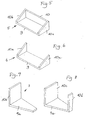
- the individual building modules each consist of a horizontal one Base plate 9 and one or more vertical wall plates 10. Die Inner surfaces of the horizontal floor panels 9 each form floor sections of a building.
- the vertical wall plates 10 of the building modules 1 to 8 form in usually load-bearing floor-to-ceiling sections of a building, each on a building module of the next higher one on its upper horizontal end faces Floor level of the building or also in a sloping form Wear roof structure.
- the outer surfaces of the base plates 9 each form parts of the outer surface of the lower floor of a building or ceiling sections of an upper one Storey of a building.
- the base plates 9 each have a rectangular shape Floor plan of z. B. 630 cm in length and 100 cm in width. 7 and 8 the base plates 9a each have an elongated, isosceles trapezoidal Floor plan, with the parallel end faces of the base plates 9a each one Distance from z. B. can have 630 cm.
- the load-bearing floor-to-ceiling wall panels 10 of building modules 1 to 4 and 8 and 9 are each rectangular. They have a free horizontal top End face for supporting an upper building module.
- the two storey-high Wall plates 10 are located on the opposite broad sides of the Base plate 9.
- the building module according to FIG. 2 again consists of a rectangular base plate 9 z. B. in the dimensions of the base plate 9 of FIG. 1st
- Fig. 3 are located on the two opposite longitudinal sides and the two opposite widths of a rectangular base plate 9 one each storey-high wall plate 10, which largely adjoins one another form a closed, open interior, the one wall plate 10b a rectangular along one of the two long sides of the base plate 9 Has recess 11 through which the interior is accessible.
- Fig. 4 shows an L-shaped building module with a rectangular base plate 9 and storey-high rectangular wall plate 10 on one of the two broad sides of the Base plate 9.
- Fig. 5 adjoins the two opposite broad sides of a rectangular Base plate 9 wall plates 10a and 10b, each sloping like a roof slope on.
- a wall plate 10 along one of the two long sides of the base plate 9 connects to the two wall plates 10a and 10b, while in Fig. 6 the two Long sides of the base plate 9 are open.
- An L-shaped building module according to FIG. 7 and a U-shaped building module according to FIG. 8 point to at least one of the two opposing parallel ones Broad sides (Fig. 7) of an isosceles trapezoidal base plate 9a or two narrow sides (Fig. 8) floor-to-ceiling vertical wall panels different width, which is predetermined by the base plate 9a.
- construction modules according to FIG. 7 or 8 form a polygonal circular building with a circular outer diameter and a concentric circular inner diameter.
- the wall plates can also be beveled according to FIG. 6 be designed to a correspondingly beveled roof structure for a To be able to carry rotunda.
- the invention is based on the exemplary designs shown in FIGS. 1 to 8 in no way restricted by building modules.
- construction modules in the various designs conceivable, which are more or less but not fundamentally different from those in FIGS. 1 to 8 can distinguish, for example, shown designs without Basic principle to deviate that a load-bearing horizontal base plate, in particular made of concrete, is present on the inside of a floor section of a building and on the outside a surface section of a lowermost one Storey of a building, especially the trowel or one Surface section of a ceiling of an interior of a building can form advantageously part of the foundation in the building floor can be integrated between two foundation strips and at least one, preferably two vertical, floor-to-ceiling load-bearing wall panels with one Base plate are rigidly connected.
- the vertical wall panels can face the side Boundary edges of the base plate advantageously also by predetermined Measurements must be reset as shown below.
- the building modules can consist of reinforced concrete.
- the wall panels can be constructed from other building materials be like B. bricks and / or wood and / or steel and / or plastic.
- the Base plates of the building modules can have any type of breakthroughs, in particular for Laying shafts for electrical cables and for the accommodation of Have water supply and drain lines.
- the wall panels can each be external wall sections or inside form lying wall sections.
- the vertical wall panels can have necessary openings, especially for windows and doors.
- U-shaped can be used to build a building Construction modules are used in which at least one of the two Wall plates advantageously from the boundary edge of one broad side of the Base plate is reset by a predetermined dimension "L" (Fig. 9).
- FIG. 9 is a perspective illustration of an example of a partial section of a Building section of two U-shaped building modules 1 a shown, in which the advantageously over the same dimension "I" protruding plate parts of the Base plates 1 a face each other. Between the protruding ones an intermediate plate 12 is inserted in both plate parts.
- the dimensions can advantageously be chosen so that the one behind the other vertical wall panels have the same distances from each other. The Connection of the intermediate plate 12 to the two protruding plate parts is particularly favored.
- FIG. 10 is a perspective view of a similar to the example of FIG. 9 Building section from a U-shaped building module 1 b shown here both opposing wall panels 10e advantageously each around the Distance "L" from the boundary edge of the associated broad side of the base plate are reset. Closes the two protruding parts of the base plate 9c each have an L-shaped construction module shown in FIG. 4 with the free end of it Base plate 9 on. Here too, the connection is particularly favored.
- the dimensions of the building modules can advantageously be chosen so that that the vertical wall panels lying one behind the other the have the same distances.
- FIG. 11 shows an example of a basement or the bottom floor of one Building from a middle U-shaped building module 1 (Fig. 1) and two outer in each case longitudinally connected construction modules 2 (Fig. 2).
- the three building modules can advantageously be connected and formed with one another in a water-tight manner such a dense trough-shaped basement or a lower floor that is protected against flooding.
- FIG. 12 shows an exemplary floor of a building made up of a building module 2 (Fig. 2) and two identical U-shaped building modules 1 (Fig. 1) and three identical Building modules 4 (Fig. 4).
- the dimensions are advantageously chosen so that that the building modules 2 and 1 have one of three vertical ones open at the top Form walls enclosed space 13, which is open to one long side.
- the free ends of the base plates 9 are on the open long side of the space 13 three L-shaped building modules 4 lying side by side alongside one another (FIG. 4) connected.
- the dimensions here are e.g. B. selected so that the rectangular Base plates 9 of the building modules 2 and 1 have a length of 600 cm and the widths of the rectangular base plates of the L-shaped building modules 4 each 200 cm make up a total of 600 cm.
- the characteristic of the example designed floor of a building according to FIG. 12 is that the Room 13 on the L-shaped building modules 4 from two opposite sides is freely accessible.
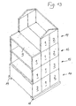
- Fig. 13 shows an example of a building with a water pressure-tight Basement 14 on which three floors 15, 16 and 17 are placed.
- the basement 14 is in the form of a watertight trough corresponding to FIG. 11 educated.
- the subsequent three floors 15, 16 and 17 each exist from two U-shaped building modules 1 (Fig. 1), the back of each building three-sided closed building modules 2 (Fig. 2) are completed as it third floor 17 of a U-shaped and a three-sided closed Building modules 1 and 2 shows that carry a roof structure, not shown here.
- the Front sides of the 1st and 2nd floors 15 and 16 are still in the example case unfinished and the foremost of the two U-shaped components of the second floor 16 is here covered, for example, by a base plate 9.
- the building of FIG. 13 in a partially unfinished state has one For example, a square layout of 630 x 630 cm. It is resting advantageously on a foundation composed of two parallel foundation strips 18 and 19.
- the multi-part bottom of the particularly pressurized water-tight Basement 14 is designed so that the foundation-free Space between the foundation strips in the bottom of the basement is integrated.
- FIGS. 14 to 19 show connecting means, for example between horizontal floor panels and vertical wall panels and between the wall panels of a building module and the floor panel of an adjacent one Building module.
- connection means shown in FIGS. 14 to 18 for two in one plane Adjacent floor panels of two building modules are appropriate for the Connection of a vertical wall plate of a lower module from the Base plate of an overlying construction module suitable.
- the connecting means according to the invention include in building modules horizontal groove profiles along the broad sides of the floor slabs and vertical Groove profiles along the vertical end faces of the wall panels.
- the groove profiles essentially have a U-shaped profile.
- Profiles are mirror images of each other and form fillable fillers Terminal cavities.
- the groove profiles are advantageously such trained that the scarf body in the manufacture of the floor and the Wall panels can be easily stripped and that the filler can easily be in insert the cavities between two adjacent floor or wall panels to let. Since two floor panels to be connected together in a horizontal Level and two wall panels to be connected in a vertical Level, there are different tasks to complete horizontal connection cavities, so that the bottom and the wall-side profiles can be designed differently.
- connection 14 shows a connection of two only in their connection areas on both sides shown floor panels 9 of two adjacent building modules.
- the threaded bolt 29 can also be designed such that it is on one (left) end instead of the nut 34 has a fixed bolt head. So that Threaded bolt is completely displaceable in the left base plate 9, the Diameter of the channel 28 have a correspondingly wide diameter.
- the threaded bolt is inserted into one (left) Base plate 9 inserted. Then the other (right) base plate 9 in brought the connection position. The threaded bolt 29 in the left base plate 9 is moved into its connection position so that the screw connection can be made.
- an additional coaxial channel corresponding to channel 28 also can start from the recess 27 so that the threaded bolt in front of the Assembly can either be inserted into the left or right base plate. It it is clear that the funnel-shaped recesses also have a cylindrical shape can have.
- a rubber-elastic sealing cord 38 is present.
- semicircular grooves 39 and 40 which are opposite each other in the connection position of the base plates.
- Sealing cord 38 inserted which has such a diameter that it at the Bracing the two base plates to achieve a secure pressurized water-tight connection of the base plates 9 deformed sufficiently elastically becomes.
- FIG. 15 shows a top view
- FIG. 16 shows a top view socket-shaped formwork bodies 41 and 42 with tubular lugs 43, 44 and 45, 46 for plugging in lost formwork tube pieces 47, 48 and 49, around the channels 24, 25 and 28 and the corresponding recesses 26 and 27 (Fig. 14) in the manufacture of the base plates 9 made of concrete to get.
- FIG. 15 shows a top view of the connecting position of the threaded bolt 29 (FIG. 14) which is supported here on special annular disks 32a, 33a which the Inner rounding of the lost formwork body 41 and 42 are adjusted.
- FIG. 17 shows the socket-like formwork body in a perspective view 41 with the attached two formwork pipe sections 47 and 48. It is lost formwork bodies, each in the finished floor slabs remain (are lost).
- the formwork body 41 corresponds to the formwork body 42, in which only the formwork tube piece 49 is attached. 16 shows that the threaded bolt 29 before assembly in the formwork body 41 with the two plugged formwork pipe sections 47 and 48 completely finds place.
- the cavity between the Potted opposite groove profiles 20 with a filling compound.
- the Recesses 36 and 37 are optionally cast with or are with Lids closed for later disassembly.
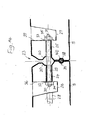
- FIG. 18 shows a top view of an intersecting double screw connection for example, two adjacent floor panels 9 of two in one plane adjacent building modules.
- Corresponding double screw connections can be used to connect vertical wall panels between two adjacent ones Building modules or for connecting vertical wall panels from the bottom Building modules can be provided with building modules lying on base plates.
- connection level 50 and 51 there are two first channels, each running transversely to the connection level 50 and 51, each connecting to a socket-like recess 50 'and 51'.
- intersection 57 lies in a cylindrical recess 58, each of semi-cylindrical recesses on the opposite narrow sides of the two base plates 9, 9 are formed.
- the intersection 57 forms the center of the situation a threaded sleeve 57 'with four at right angles to each other Threaded connections.
- channels 50, 51 and 54, 55 extending at right angles to one another there are tie rods 60, 61 and 62, 63, each with their front ends Connect one of the threaded connections of the threaded sleeve 57 'and each with their rear thread ends in the socket-like recesses 50 ', 51' and 61 ', 62' protrude where nuts 64, 65 and 66, 67 are screwed on, each of which adjoins Support the washers.
- By evenly tightening the four nuts with predetermined force there is a firm connection between the base plates 9 in Area of intersection 57.
- the recesses 50 ', 51' and 61 ', 62' can also be with lids for one any later disassembly will be closed.
- crossed connection can also be used to adjust the adjacent floor or cover plates.
- a cellar can advantageously be used as a watertight tub form.
- the buoyancy locks can be used with advantage e.g. out reinforcements attached on the outside, over which after the A spur made of in-situ concrete can be cast in basement, the size of which is dependent on the possible buoyancy forces.
- the basement can also use concrete slabs on the basement outer walls be connected, on which the earth rests.
- a multi-storey building made up of individual building modules of the above type To be able to erect, the head end faces of wall panels that Building modules in a lower floor level belong to the outside of Ceiling panels can be firmly connected to building modules in one belong to the next higher floor level.
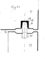
- FIG. 19 shows an example of a connection 68 between a head-side Section of a vertical wall plate 69 of a lower, not shown Construction module z. B. according to one of FIGS. 1 to 4 and 7 and 8 and a section a horizontal base plate 70 with a rigidly connected part a vertical wall plate 71 of an upper building module, the position on the vertical wall plates of the lower building module is placed, wherein in Fig. 19 only the vertical wall plate 69 is shown.
- the lower module can, for. B. also according to one of FIGS. 1 to 4 and 7 and 8 shown building modules be trained.
- connection 69 includes a socket-like recess 72, which extends transversely to the extends vertical wall plate 69 of the lower module and from the Inside 69 'of the vertical wall plate 69 is accessible. Of the Recess 72 extends from a first vertical channel 73 that connects to a head-side one Groove profile 74 of the wall plate 69 shoots.
- the channel 73 is aligned with a vertical blind channel 73 'on Corresponding groove profile 75 on the outside 70 'of the bottom plate 70 of the upper construction module connects.
- the two mirror-image trained equally Groove profiles 74 and 75 extend parallel to the horizontal outer Long edge on the head side of the vertical wall plate 69 of the lower Construction module and parallel to the opposite horizontal outer Longitudinal edge of the bottom plate 70 of the upper building module.
- a threaded bush 76 is firmly fitted into the firm connection of the upper module to the lower module the front end 77 of a threaded bolt 78 which extends through the channel 73, the Bolt head 79 in the recess 72 after screwing over a Disc 80 is supported on a side wall of the recess 72.
- the channel 73 in FIG vertical wall plate 69 a slightly larger diameter than that Diameter of the bolt head 79. Also includes the recess Blind channel 81 on, which is aligned with the channel 73. In the blink channel 81 with the The diameter of the channel 73 can advantageously be the bolt 78 before it Immerse assembly so that the bolt 78 is completely in the head part of the Wall plate 69 comes to rest.
- the groove profile 74, 75 and the free Annulus of channel 73 via a channel 82 with a dashed line poured liquid filling compound the from the inside 70 'of the bottom plate 70th of the upper module goes out and connects to the groove profile 74, 75.
- elastic cords 74 'and 75' in the gap between the vertical lower wall plate 69 and the horizontal upper floor plate 70 ', which along the inner and outer longitudinal edges of the head portion of wall plate 69 and the outer surface 70 'of the base plate 70 the groove profile 74, 75th sealed inside and out.
- the bush-like recess 68 can be filled with a filling compound or for later disassembly a lid, not shown, are closed.
- the socket-like recess 72 and the channels 73, 73 'and 81 are at Building modules made of concrete formed by lost formwork bodies, which at the Production of the building modules in steel formwork by known methods with high positional accuracy in the millimeter range.
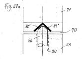
- FIG. 20 shows in vertical section a device for adjusting the upper one 19 in the exactly horizontal and vertical position of the head end face of the vertical wall plate 69 shown in FIG. 19 of a lower module as a prerequisite for channel 73 in the vertical wall plate 69 of the lower module with the channel 73 'in the adjacent base plate 70 of the upper building module is exactly aligned.
- the funnel-shaped angle iron 83 in the corner points of the head end face of the vertical wall plate 69 of the lower building module and correspondingly at the corner points of the opposite vertical wall plate of the lower building module, which is in a precisely predetermined position has been concreted into the area of the groove 74 as a lost formwork part in the head end face of the wall plate 69.
- the funnel-shaped angle iron 83 forms a lower calibration element.
- the upwardly open angle iron 83 serves as a bearing for a ball 85 with a selected diameter. The ball projects vertically upwards from the angle iron 83 by a selected amount.
- a corresponding funnel-shaped angle iron 84 fixed concreted. This is also a part of the manufacture of the construction module lost formwork part.
- the funnel-shaped angle iron 83 forms one lower calibration element.
- the common vertical central axis 85 'of both opposite one another Calibration elements 83, 84 have such a precise distance from the vertical outer wall of the upper module 71 and the opposite vertical outer wall of the lower module on that when placing the upper construction module 71 with its upper calibration element 84 onto the ball 85 the upper module 71 in the millimeter range in the correct position compared to the lower building module, in which the outer surfaces of the superimposed Building modules and the bores 73, 73 '(Fig. 19) each in the vertical cursed with each other. If the wall plate 69 of the lower module from the vertical position deviate somewhat, so the wall plate 69 when the upper construction module through the balls 85 coming to lie one above the other Calibration elements on the corner areas of the wall plate 69 in the exact vertical position pressed.
- Corresponding upper and lower calibration elements 83, 84 with inserted Balls 85 are located at the four corner points between the head ends Ends of two opposite vertical wall parts of a lower building module and the opposite corner points on the outer bottom surface of the attached top construction module.
- an upper construction module in the Horizontal compared to the lower building module can be according to an exact Height measurement z.
- the individual ball diameters determine that the upper building module is opposite the lower building module is exactly in the horizontal position. There are balls for this during assembly different diameters in the necessary tolerance range.
- the horizontal adjustment of the building modules of a building in its lowest Floor level using four balls on a foundation can be used with the Ball adjustment are made in a corresponding manner, then for a Building module on the foundation side in outer corner points four corresponding lower ones Calibration elements 83 for taking the adjustment balls with selected ones Diameters are provided in the corresponding upper Calibration elements 84 at the outer corner points of the outer floor surface of a building module lying on the foundation.
- the third building module is again in the same level using four Balls adjusted and then screwed to the second module, and so on to the lowest floor level of the building according to the invention in the correct position is mounted.
- the next, second level can then be installed on the lowest level Storey from individual building modules, with the four balls in the calibration elements for vertical and horizontal Centering of an upper module compared to the lower module.
- the balls can be metal balls in the angle iron lie.
- the automatic centering of the building modules according to the invention is based on the Usage balls not restricted. It can also consist of bullets act sufficiently hard plastic. This also applies to the choice of materials for the funnel-shaped calibration elements.
- calibration elements can be the base plates of Building modules have hemispherical recesses on the outside into which automatic centering corresponding hemispherical projections on the Engage the end faces of the wall elements. So the hemispherical Concrete projections on the end faces of wall elements a horizontal plane tangential hemispherical cap-like attachments are optionally selectable Thickness made of metal available to balance the hemispherical Concrete projections can be placed on these if necessary.
- the invention is based on the above self-centering of the building modules horizontal position using transverse bolts (e.g. Fig. 18) or in the vertical position by means of balls not limited.
- corresponding centering pins can be used instead of the ball centerings or centering pin 86 with a frustoconical end 86 'are used, those on the foundation or on the end faces of vertical Wall parts of a lower building module in correspondingly spherical recesses Intervene in the bottom of a next building module, self-centering. It is of advantage if the individual centering bolts are height-adjustable. As a result, the end faces of the ends of the centering pin can be in one horizontal level can be set so that after touching down the top Building module on the lower building module with the centering bolt the upper building module comes to a millimeter in the horizontal.
- centering bolts 86 To adjust the height of the centering bolts 86 are in the foundation and / or in the Wall parts 69 of building modules vertical recess 90 available in the Firmly engage threaded sleeves 91.
- the upper spherical and the free Bevels or tips 86 'ends of the centering pin 86 can be passed through Adjust screwing to a precisely measured height, in which the upper Ends lie exactly in a horizontal plane.
- the outside of the base plate of an upper building module is located in each fixed position four centering sleeves 89 as lost formwork parts. Make it up the centering pins 86 each have lower calibration elements and the centering sleeves each upper calibration elements that work together in pairs.
- Fig. 21 pot-shaped centering sleeves shown can also be funnel-shaped be, as Fig. 21 a shows.
- An essential idea of the invention is that the foundation except for narrow foundation strips along the parallel longitudinal and / or Transverse sides of the building according to the invention in the floor of the basement or at missing basement is integrated into the ground floor. This assumes that at a building according to the invention at least the lowest floor is composed of several construction modules according to the invention.
- the at least two identical parallel strips approximately at a distance from the parallel Longitudinal and / or transverse sides of the building existing strip foundations can each in cross section z. B. have a trapezoidal shape. The This significantly reduces the cost of foundation work.
- the width of the prefabricated strip foundations depends on the load through the building and depending on the soil parameters. different The width of the foundation strips made of concrete can be adjusted using a variable steel formwork getting produced.
- the foundations are trapezoidal in cross section with the wider footprint and the narrower building support surface on the Head turned. This can remove the foundation strips from the formwork to be pulled.
- the side formwork advantageously does not have to be opened become.
- the centering means according to the invention described above can be Concrete into the foundation strips with millimeter precision, so that after a exact determination of the position of the foundation strips with regard to their parallelism and the arrangement of their contact surfaces in a horizontal plane Storage of the building modules for the lowest floor level can be made can, the basis for this is that the other floors are each in have horizontal levels assembled.
- An essential idea of the invention is also a to be able to build largely earthquake-proof buildings if the the above strip foundation technique according to the invention is applicable, d. H. if at least the bottom floor, especially the basement construction modules according to the invention is composed, on centering balls or Centering pin rests, which act like joints during earthquakes, the impact energy can counteract largely without breakage.
- 22 a shows an inventive three-story building 91 with a Basement 92, a ground floor 93, an upper floor 94 and one mounted roof structure 95.
- balls 98, 99 made of steel or hard Plastic arranged so that the building on the balls in the event of earthquakes is movable. So that the lateral displacement is optimally guaranteed are on the outer long sides of the strip foundations 96 and 97 vertical support walls 100 and 101 rigidly connected, which is a contact of the ground with the outer surface of the basement, preventing a building free in the space between the retaining walls during earthquakes on the balls is movable.
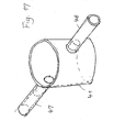
- 22 b shows an advantageous example of the arrangement of two balls 96 and 97 only partially between a flat pad 102 on the outer bottom surface shown building module of a building according to the invention and one in the Strip foundation 96 concreted steel pan 103, in which the ball 98 in its Normal position is in the lowest point of the tub.
- the Buildings should not come out of contact with sphere 98 in the event of earthquakes.
- the ball diameter can correspond to the given requirements can be determined.
- the balls can be simple rolling bodies, one have largely spherical surface. Depending on the number of Balls can also consist of hard plastics.
- the casting compounds between the Connection profiles of adjacent building modules the impact energies of Catch earthquake shocks through deformations or breakages without this three-dimensional network of connection points in a collapse hazard Way leaves. Rather, the filigree network of connection points ensures between the individual building modules for mutual support and wedging or jamming of the individual building modules also in shifted to each other Positions that cause the building to collapse after earthquake strikes largely prevent. If the building modules are clamped crosswise with each other, e.g. B. in Fig. 18 can in special cases also on a potting Connection profiles are omitted, which is the case with earthquake-prone buildings Can be an advantage.
- Fig. 23 shows a horizontally divided strip foundation, between which the Balls are arranged as in Fig. 22.
- the relatively broad Strip foundation with a double row of balls 96 a and 96 b is used for Edition of two neighboring buildings according to the invention by one narrow air gap 106 are separated from each other.
- Adjustment devices according to the invention, not shown here, for example how 20 or 21 may be arranged so that the bottom floors of the Buildings on the two-part strip foundation with millimeter accuracy Can be adjusted horizontally and also an extensive Movability of the buildings against earthquake impact caused by balls 96 a and 96 b is secured between two foundations, thereby reducing impact energy from To be able to absorb earthquake shocks as far as possible.
- FIG. 24 shows a top view of a section of a floor of a building Building, which is composed of individual building modules and one Has spiral staircase 107.
- the floor consists of two U-shaped building modules (Fig. 1) between them an L-shaped building module (Fig. 4) with a shortened, as a stair center trained construction module (Fig. 2), include here z. B. a conventional one Includes spiral staircase 107.
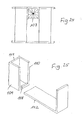
- the building module 111 (FIG. 2) shown in perspective in FIG. 25 exists for formation a stair tower made of a short square floor slab 108 for example with the dimensions 180 x 180 cm, on the three storey-high Connect wall plates 109, 110, 11, which are U-shaped in cross-section each other close.
- FIG. 26 shows a top view and FIG. 27 shows a perspective view Part of a floor 113 with a staircase 114 to a lower floor of a building according to the invention.
- the part of the floor 113 shown here consists of two outer U-shaped ones Building modules 115, 119 (Fig. 1) in normal length, e.g. of 630 cm, and two shortened U-shaped building modules 117 lying between these building modules, 118 (Fig. 1), e.g. B. with a length of 450 cm.
- the stairwell for the stairs 114 is one of the vertical wall plates 119 and 120 and one separate wall plate 121 bounded to the two wall plates 122 and 123 the U-shaped building modules 115 and 119 is shot.
- the invention is not restricted to the exemplary embodiments.
- the specialist This opens up a large number of variants that are not within the scope of the invention leave.
Landscapes
- Engineering & Computer Science (AREA)
- Architecture (AREA)
- Business, Economics & Management (AREA)
- Emergency Management (AREA)
- Environmental & Geological Engineering (AREA)
- Civil Engineering (AREA)
- Structural Engineering (AREA)
- Physics & Mathematics (AREA)
- Electromagnetism (AREA)
- Buildings Adapted To Withstand Abnormal External Influences (AREA)
- Working Measures On Existing Buildindgs (AREA)
Applications Claiming Priority (2)
| Application Number | Priority Date | Filing Date | Title |
|---|---|---|---|
| DE10255335 | 2002-11-27 | ||
| DE10255335A DE10255335A1 (de) | 2002-11-27 | 2002-11-27 | Aus einzelnen Baumodulen aufgebautes Gebäude |
Publications (2)
| Publication Number | Publication Date |
|---|---|
| EP1426510A2 true EP1426510A2 (fr) | 2004-06-09 |
| EP1426510A3 EP1426510A3 (fr) | 2006-02-08 |
Family
ID=32308752
Family Applications (1)
| Application Number | Title | Priority Date | Filing Date |
|---|---|---|---|
| EP03027387A Withdrawn EP1426510A3 (fr) | 2002-11-27 | 2003-11-27 | Bâtiment réalisé en modules de construction uniques |
Country Status (2)
| Country | Link |
|---|---|
| EP (1) | EP1426510A3 (fr) |
| DE (1) | DE10255335A1 (fr) |
Cited By (4)
| Publication number | Priority date | Publication date | Assignee | Title |
|---|---|---|---|---|
| CN106939649A (zh) * | 2017-04-28 | 2017-07-11 | 重庆昊色堂建筑设计咨询有限公司 | 组合式房屋单元及房屋 |
| CN113668713A (zh) * | 2021-09-01 | 2021-11-19 | 扬州工业职业技术学院 | 一种建筑设备用装配式集成连接装置 |
| CN115126079A (zh) * | 2017-07-04 | 2022-09-30 | 三能集成房屋股份有限公司 | 筒塔式建筑物及其施工方法 |
| WO2025245636A1 (fr) * | 2024-05-31 | 2025-12-04 | Bloxtone Building Solutions Inc. | Systèmes et procédés de fabrication de blocs de construction modulaires en béton et de bâtiments modulaires |
Families Citing this family (4)
| Publication number | Priority date | Publication date | Assignee | Title |
|---|---|---|---|---|
| DE202014004059U1 (de) * | 2014-05-15 | 2015-08-24 | Glatthaar - Fertigkeller Gmbh & Co. Kg | Fertigkeller |
| DE102022121338A1 (de) * | 2022-08-23 | 2024-02-29 | Daliborka Djukic-Schröder | Energieraum als Energiezentrale |
| US12270195B2 (en) | 2022-08-23 | 2025-04-08 | Daliborka Djukic-Schröder | Energy room as an energy center |
| DE102023126648A1 (de) * | 2023-09-29 | 2025-04-03 | Peter Aurnhammer | Fertigkeller |
Family Cites Families (12)
| Publication number | Priority date | Publication date | Assignee | Title |
|---|---|---|---|---|
| US2064791A (en) * | 1936-03-27 | 1936-12-15 | Faber Herbert Alfred | Method of assembling blocks and structure resulting therefrom |
| DE1996702U (de) * | 1968-06-08 | 1968-11-14 | Gerhard Dr Ing Stapelfeldt | Vorrichtung fuer die montage von betonfertigteilen |
| DE7006131U (de) * | 1970-02-20 | 1970-07-23 | Kuester Hermann | Erdbebensicheres fertighaus. |
| DE2323994A1 (de) * | 1973-05-09 | 1974-11-28 | Winfried Mammach | Bausystem der skelettbauweise |
| US4073102A (en) * | 1973-05-29 | 1978-02-14 | Fisher John Sergio | Premanufactured modular town house building construction |
| IT1045178B (it) * | 1975-02-11 | 1980-05-10 | Colma Ibero | Strutture prefabbricate di tipo modulare atte a consentirel erezione di edifici |
| DE8216902U1 (de) * | 1982-06-11 | 1982-09-09 | Dyckerhoff & Widmann AG, 8000 München | Vorrichtung zum verbinden von stahlbetonfertigbauteilen |
| DE3338142A1 (de) * | 1983-10-20 | 1985-05-02 | Hans-Dieter 2056 Glinde Rathmann | Kombinationssystem aus vorgefertigten elementen fuer die errichtung eines gebaeudes |
| DE3411210A1 (de) * | 1984-03-27 | 1984-08-09 | Joachim 8904 Friedberg Weigl | Raumgrosses u-stahlbetonprofil |
| DE3605166A1 (de) * | 1986-02-14 | 1987-08-27 | Henning Maerkische Kies Sand | Planelement-verbund |
| DE8814835U1 (de) * | 1988-11-29 | 1989-03-09 | Dyckerhoff & Widmann AG, 81902 München | Vorrichtung zum Zusammenspannen von Fertigbauteilen aus Stahlbeton |
| TR200000330T2 (tr) * | 1997-08-08 | 2000-05-22 | Robinson Seismic Limited | Enerji emici |
-
2002
- 2002-11-27 DE DE10255335A patent/DE10255335A1/de not_active Withdrawn
-
2003
- 2003-11-27 EP EP03027387A patent/EP1426510A3/fr not_active Withdrawn
Cited By (5)
| Publication number | Priority date | Publication date | Assignee | Title |
|---|---|---|---|---|
| CN106939649A (zh) * | 2017-04-28 | 2017-07-11 | 重庆昊色堂建筑设计咨询有限公司 | 组合式房屋单元及房屋 |
| CN115126079A (zh) * | 2017-07-04 | 2022-09-30 | 三能集成房屋股份有限公司 | 筒塔式建筑物及其施工方法 |
| CN115126079B (zh) * | 2017-07-04 | 2023-07-11 | 三能集成房屋股份有限公司 | 筒塔式建筑物及其施工方法 |
| CN113668713A (zh) * | 2021-09-01 | 2021-11-19 | 扬州工业职业技术学院 | 一种建筑设备用装配式集成连接装置 |
| WO2025245636A1 (fr) * | 2024-05-31 | 2025-12-04 | Bloxtone Building Solutions Inc. | Systèmes et procédés de fabrication de blocs de construction modulaires en béton et de bâtiments modulaires |
Also Published As
| Publication number | Publication date |
|---|---|
| DE10255335A1 (de) | 2004-06-17 |
| EP1426510A3 (fr) | 2006-02-08 |
Similar Documents
| Publication | Publication Date | Title |
|---|---|---|
| EP3690159B1 (fr) | Enveloppe de bâtiment et procédé d'isolement thermique des enveloppes de bâtiment en béton | |
| EP3781747B1 (fr) | Procédure d'établissement d'un fondement pour une éolienne | |
| DE3038407A1 (de) | Baublock | |
| DE2835425A1 (de) | Masseinheitliches element fuer fertigbauweise | |
| EP1426510A2 (fr) | Bâtiment réalisé en modules de construction uniques | |
| DE2503479A1 (de) | Vorgefertigtes, transportables raumelement | |
| EP4495421A2 (fr) | Fondation pour une éolienne | |
| DE4407000C2 (de) | Rundstütze zum Aufbau von Gebäuden | |
| DE2810317A1 (de) | Verfahren zum herstellen von gebaeuden fuer wohn-, sozial-, oder gewerbezwecke und mit diesem verfahren erzieltes gebaeude | |
| EP0631022B1 (fr) | Elément tridimensionnel pour la construction d'ouvrages et procédé pour sa fabrication | |
| WO2010075855A1 (fr) | Système de goujon pour construction en béton | |
| EP0645501B1 (fr) | Méthode pour la production de modules préfabriqués pour la construction de bâtiments et module préfabriqué | |
| EP1394339A2 (fr) | Immeuble de garage réalisé en éléments préfabriqués en béton | |
| DE3925591A1 (de) | Bausatz fuer die erstellung eines balkons | |
| DE2612048A1 (de) | Fertigteilebauwerk in modulbauweise | |
| AT372734B (de) | Baukonstruktion | |
| EP0480295B1 (fr) | Ensemble pour la construction d'une maison d'habitation ou de vacances | |
| EP4617442A1 (fr) | Module de construction pour un bâtiment modulaire, unité d'habitation modulaire et bâtiment modulaire | |
| DE1800167A1 (de) | Mehrgeschossiges Gebaeude,insbesondere Fertighaus mit einem Treppenhaus aus monolithischen Raumkaesten | |
| DE2244886C3 (de) | Mehrgeschossiges Gebäude und Verfahren zu seiner Herstellung | |
| DE102006001843B4 (de) | Schweinestall-Bausatz | |
| DE10046138C2 (de) | Fertigmodul für Gebäudeetagen eines Hauses und Verfahren zur Herstellung und Aufbau von Gebäudeteilen aus Fertigmodulen | |
| AT230069B (de) | Bauwerk | |
| DE1609361C3 (de) | Gebäude mit vorgefertigten, geschlossenen, einzelligen Rahmenelementen aus Stahlbeton | |
| DE4230836A1 (de) | Verbindung zwischen vorgefertigten, geschosshohen wandeinheiten und vorgefertigten geschossplatten und verbindungsmittel fuer eine solche verbindung |
Legal Events
| Date | Code | Title | Description |
|---|---|---|---|
| PUAI | Public reference made under article 153(3) epc to a published international application that has entered the european phase |
Free format text: ORIGINAL CODE: 0009012 |
|
| AK | Designated contracting states |
Kind code of ref document: A2 Designated state(s): AT BE BG CH CY CZ DE DK EE ES FI FR GB GR HU IE IT LI LU MC NL PT RO SE SI SK TR |
|
| AX | Request for extension of the european patent |
Extension state: AL LT LV MK |
|
| PUAL | Search report despatched |
Free format text: ORIGINAL CODE: 0009013 |
|
| AK | Designated contracting states |
Kind code of ref document: A3 Designated state(s): AT BE BG CH CY CZ DE DK EE ES FI FR GB GR HU IE IT LI LU MC NL PT RO SE SI SK TR |
|
| AX | Request for extension of the european patent |
Extension state: AL LT LV MK |
|
| RIC1 | Information provided on ipc code assigned before grant |
Ipc: E04B 1/61 20060101ALI20051220BHEP Ipc: E04H 9/02 20060101ALI20051220BHEP Ipc: E04B 1/348 20060101AFI20040309BHEP |
|
| AKX | Designation fees paid | ||
| STAA | Information on the status of an ep patent application or granted ep patent |
Free format text: STATUS: THE APPLICATION IS DEEMED TO BE WITHDRAWN |
|
| 18D | Application deemed to be withdrawn |
Effective date: 20060809 |
|
| REG | Reference to a national code |
Ref country code: DE Ref legal event code: 8566 |