EP1429131B1 - Verfahren und Gerät zur Detektion einer Drucksensor-Fehlfunktion eines Luftfahrzeug-Anemometers - Google Patents
Verfahren und Gerät zur Detektion einer Drucksensor-Fehlfunktion eines Luftfahrzeug-Anemometers Download PDFInfo
- Publication number
- EP1429131B1 EP1429131B1 EP03292755A EP03292755A EP1429131B1 EP 1429131 B1 EP1429131 B1 EP 1429131B1 EP 03292755 A EP03292755 A EP 03292755A EP 03292755 A EP03292755 A EP 03292755A EP 1429131 B1 EP1429131 B1 EP 1429131B1
- Authority
- EP
- European Patent Office
- Prior art keywords
- aircraft
- altitude
- pressure
- threshold
- failure
- Prior art date
- Legal status (The legal status is an assumption and is not a legal conclusion. Google has not performed a legal analysis and makes no representation as to the accuracy of the status listed.)
- Expired - Lifetime
Links
- 238000000034 method Methods 0.000 title claims description 21
- 230000007257 malfunction Effects 0.000 title claims description 5
- 238000001514 detection method Methods 0.000 title abstract description 6
- 239000000523 sample Substances 0.000 claims abstract description 11
- 238000009530 blood pressure measurement Methods 0.000 claims description 11
- 230000008878 coupling Effects 0.000 claims 3
- 238000010168 coupling process Methods 0.000 claims 3
- 238000005859 coupling reaction Methods 0.000 claims 3
- 241001481828 Glyptocephalus cynoglossus Species 0.000 claims 1
- 238000009434 installation Methods 0.000 abstract 1
- 238000012800 visualization Methods 0.000 description 8
- 238000012550 audit Methods 0.000 description 5
- 238000005259 measurement Methods 0.000 description 4
- 238000012423 maintenance Methods 0.000 description 3
- 238000012544 monitoring process Methods 0.000 description 3
- 230000011664 signaling Effects 0.000 description 3
- 238000005406 washing Methods 0.000 description 3
- 241000196324 Embryophyta Species 0.000 description 2
- 238000004891 communication Methods 0.000 description 2
- 241001080024 Telles Species 0.000 description 1
- 240000008042 Zea mays Species 0.000 description 1
- 239000000853 adhesive Substances 0.000 description 1
- 230000001070 adhesive effect Effects 0.000 description 1
- 239000002390 adhesive tape Substances 0.000 description 1
- 238000004378 air conditioning Methods 0.000 description 1
- 230000000295 complement effect Effects 0.000 description 1
- 238000010586 diagram Methods 0.000 description 1
- 230000000694 effects Effects 0.000 description 1
- XLYOFNOQVPJJNP-UHFFFAOYSA-N water Substances O XLYOFNOQVPJJNP-UHFFFAOYSA-N 0.000 description 1
Images


Classifications
-
- G—PHYSICS
- G01—MEASURING; TESTING
- G01L—MEASURING FORCE, STRESS, TORQUE, WORK, MECHANICAL POWER, MECHANICAL EFFICIENCY, OR FLUID PRESSURE
- G01L27/00—Testing or calibrating of apparatus for measuring fluid pressure
- G01L27/007—Malfunction diagnosis, i.e. diagnosing a sensor defect
Definitions
- the present invention relates to a method and a device for detecting the failure of a pressure sensor of an air-power plant of an aircraft, which comprises at least two pressure sensors.
- said air-pressure unit comprises pressure sensors which are connected by tubes to probes which pass through the fuselage of the aircraft.
- the personnel responsible for carrying out a washing operation of the aircraft frequently stick a piece of tape on each of the sensors of the air-power unit, to prevent water from entering the tube during said washing. If they forget to remove one of said pieces of adhesive tape after washing, the corresponding pressure sensor will fail during the next flight of the aircraft, since it will not be able to measure the pressure of the outside air at fuselage. It will actually measure the air pressure in the tube that is closed, at its end on the probe side, by the adhesive piece.
- Another example of failure concerns the case where maintenance personnel disconnect the tube and the pressure sensor at a suitable connector, for example to clean the inside of this tube. If they forget to reconnect the tube to the pressure sensor after carrying out the maintenance operation, said pressure sensor will also fail, since it will measure the air pressure inside the fuselage instead of measuring the air pressure outside the fuselage.
- the present invention aims to overcome these disadvantages. It relates to a method for detecting, quickly and reliably, and at reduced cost, the failure of a pressure sensor of an air-power plant of an aircraft, which comprises at least two pressure sensors.
- This predetermined speed threshold for example 25 m / s (about 50 knots), is preferably chosen so that the effect of a lateral wind corresponding to a wind of maximum intensity does not lead to the unjustified signaling of a failure during take-off of the aircraft.
- This second sequence of steps B1) to B9) has the advantage of allowing the detection of the simultaneous failure of several pressure sensors of the same air-pressure unit. It may for example be implemented by an alarm monitoring / signaling system provided on the aircraft.
- said altitude threshold is lower than the altitude reached by the aircraft, at said predetermined time after take-off, in the event of a failure. at least one of said engines.
- said predetermined time after takeoff is substantially equal to 30 seconds
- said altitude threshold is substantially equal to 30 meters (about 100 feet).
- At least one of said detectors is integrated in a pneumatic connector for connecting a pneumatic tube associated with a probe, to the corresponding pressure sensor.
- the present invention also relates to a device for detecting the failure of a pressure sensor of an air-power plant of an aircraft, which comprises at least two pressure sensors.
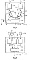
- the figure 1 is the block diagram of a device according to the invention.
- FIGS. 2 and 3 schematically illustrate different embodiments of a central unit of a device according to the invention.
- FIGS. 4 and 5 schematically illustrate complementary elements of a central unit of a device according to the invention.
- the device 1 according to the invention and schematically represented on the figure 1 is intended for the monitoring of a conventional anemometer 2 of an aircraft, in particular of a civil transport aircraft, of which only part of the fuselage 3 has been represented on this figure 1 for reasons of simplification of the drawing.
- the purpose of the device 1 according to the invention is to detect any failure of a pressure sensor 5 of such an anemometer unit 2.
- the device 1 it is possible to quickly and reliably detect any failure of a pressure sensor 5 of the air-power unit 2, without calling on information external to this air-power unit 2, such as for example, information transmitted by other air-power units of the aircraft. This therefore makes it possible to guarantee, in the case of a plurality of air-power units on the aircraft, the strict independence of the different air-power units relative to each other.
- the two (or at least two) pressure sensors 5 of the air-power unit 2 are mounted on either side of the longitudinal axis 23 of the fuselage 3 of the aircraft, as shown in FIG. figure 1 .
- the selection means 21A which is connected by a link 27 to said means 25 orders the display of a failure information, only if, in addition to the aforementioned conditions, said air speed value is greater than said threshold of speed.
- the device 1 comprises at least three pressure sensors 5 and the calculation unit 11 comprises as many (three, four, ...) acquisition means 16 ( figure 3 ) there are pressure sensors 5.
- the device 1 may also comprise a calculation means 28 and a memory 29 which are connected (links 30 to 32) between an acquisition means 16 and the comparison means 19B, as shown in FIG. figure 4 .
- said altitude threshold is lower than the altitude reached by the aircraft, at said predetermined time after take-off, in the event of a failure of an engine of the aircraft (which is, in this case, provided with at least two engines).
- said predetermined time T after takeoff may be substantially equal to 30 seconds
- said altitude threshold may be substantially equal to 30 meters (about 100 feet).
- the device 1 may also include conventional means 33 for monitoring the engines of the aircraft. These means 33 are connected to the selection means 21B by a link 34 to inform it of any detection of a malfunction of at least one of the engines of the aircraft. In this case, when a failure of a pressure sensor 5 is detected, the selection means 21B orders the display of a failure information only if no malfunction of an engine is signaled at the same time by the sensors. means 33.
- elements 19B, 21B and 22B of the figure 4 may correspond to elements 19A, 21A and 22A of Figures 2 and 3 . However, it may also be means separate from said central unit 11.
- the embodiment of the figure 4 has the advantage of allowing the detection of the failure of two pressure sensors 5 of the same air-pressure unit 2.
- it may comprise additional elements 16, 28 and 29, as shown in phantom.
- the pressure sensors 5 ( figures 1 and 5 ) at least one detector 35 which is capable of detecting a faulty connection between the corresponding pressure sensor 5 and the probe 4 which is associated with this pressure sensor 5.
- At least one of said detectors 35 is integrated in a pneumatic connector 7 intended to connect the pneumatic tube 6 associated with a probe 4, to the corresponding pressure sensor 5.
- a detector 35 may in particular be a switch actuated by the connection of the connector 7, a laser diode, etc.
- the selection means 21 C may represent the selection means 21 A and / or the selection means 21 B, or be independent of the latter.
Landscapes
- Health & Medical Sciences (AREA)
- Chemical & Material Sciences (AREA)
- Engineering & Computer Science (AREA)
- Analytical Chemistry (AREA)
- Biomedical Technology (AREA)
- Physics & Mathematics (AREA)
- General Physics & Mathematics (AREA)
- Measuring Fluid Pressure (AREA)
- Indicating Or Recording The Presence, Absence, Or Direction Of Movement (AREA)
Claims (14)
- Verfahren zum Feststellen der Fehlfunktion eines Drucksensors (5) einer Windmesserzentrale (2) eines Flugzeugs, umfassend zumindest zwei Drucksensoren (5), wobei nach diesem Verfahren zumindest die folgende erste Reihe von Schritten durchgeführt wird:A1) Durchführen von Druckmessungen mit Hilfe der zwei Ducksensoren (5), um den ersten bzw. den zweiten Druckwert zu erhalten;A2) Berechnen der Abweichung zwischen dem ersten und dem zweiten Druckwert;A3) Vergleichen dieser Abweichung mit einem vorbestimmten Schwellenwert; undA4) wenn die Abweichung größer als der Schwellenwert ist, Anzeigen einer Information der Fehlfunktion der Windmesserzentrale (2) auf einer Anzeigevorrichtung (15), die auf dem Flugzeug montiert ist,
dadurch gekennzeichnet, dass außerdem zumindest die folgende zweite Reihe von Schritten durchgeführt wird:B1) Durchführen von Druckmessungen mit Hilfe von zumindest einem Drucksensor (5) der Windmesserzentrale (2) auf dem Flugzeug, das sich am Boden befindet, und dessen Kabine nicht unter Druck gesetzt ist, um einen dritten Druckwert zu erhalten;B2) ausgehend von diesem dritten Druckwert Berechnen einer ersten Höhe, entsprechend der Höhe des Bodens;B3) Unter-Druck-Setzen der Kabine des Flugzeugs;B4) Starten des Flugzeugs;B5) bei einer vorbestimmten Zeit nach dem Start Durchführen von Druckmessungen mit Hilfe des Drucksensors (5), um einen vierten Druckwert zu erhalten;B6) ausgehend von diesem vierten Druckwert Berechnen einer zweiten Höhe, entsprechend der Höhe des Flugzeugs;B7) Berechnen einer dritten Höhe, entsprechend der Höhe des Flugzugs bezüglich des Bodens, ausgehend von der ersten und der zweiten Höhe;B8) Vergleichen der dritten Höhe mit einer vorbestimmten Schwellenhöhe; undB9) wenn die dritte Höhe geringer als die vorbestimmte Schwellenhöhe ist, Anzeigen einer Information der Fehlfunktion der Windmesserzentrale (2) auf einer Anzeigevorrichtung (15), die auf dem Flugzeug montiert ist. - Verfahren nach Anspruch 1,
dadurch gekennzeichnet, dass außerdem die folgenden Schritte durchgeführt werden:- Messen der Geschwindigkeit des Flugzeugs bezüglich der Luft, um einen Luftgeschwindigkeitswert zu erhalten;- Vergleichen der so gemessenen Luftgeschwindigkeit mit einer vorbestimmten Schwellengeschwindigkeit; und- Anzeigen einer Information der Fehlfunktion in Schritt A4 nur dann, wenn der Luftgeschwindigkeitswert höher als die Schwellengeschwindigkeit ist. - Verfahren nach Anspruch 2,
dadurch gekennzeichnet, dass die Schwellengeschwindigkeit im Wesentlichen gleich 25 m/s ist. - Verfahren nach einem der Ansprüche 1 bis 3,
dadurch gekennzeichnet, dass der Schwellenwert im Wesentlichen gleich 30 mbar ist. - Verfahren nach einem der vorhergehenden Ansprüche, dadurch gekennzeichnet, dass die zwei Drucksensoren (5) auf beiden Seiten der Längsachse (23) der Flugzeugs, auf dem Rumpf (3) des Letzteren, montiert werden.
- Verfahren nach einem der vorhergehenden Ansprüche, dadurch gekennzeichnet, dass zumindest drei Drucksensoren (5) für die Windmesserzentrale (2) vorgesehen werden, dadurch, dass in Schritt A1) Druckmessungen mit Hilfe der drei Drucksensoren (5) durchgeführt werden, dadurch, dass in Schritt A2) alle möglichen Abweisungen zwischen den verschiedenen jeweils zwei genommenen Druckwerten berechnet werden, dadurch, dass in Schritt A3) alle so berechneten Abweichungen zum Schwellenwert verglichen werden, und dadurch, dass in Schritt A4) eine Information der Fehlfunktion je nach den verschiedenen so durchgeführten Vergleichen angezeigt wird oder nicht.
- Verfahren nach Anspruch 6,
dadurch gekennzeichnet, dass in Schritt A4) eine Information der Fehlfunktion angezeigt wird, wenn zumindest eine der Abweichungen größer als der Schwellenwert ist. - Verfahren nach Anspruch 6,
dadurch gekennzeichnet, dass in Schritt A4) eine Information der Fehlfunktion nur dann angezeigt wird, wenn alle Abweichungen größer als der Schwellenwert sind. - Verfahren nach einem der vorhergehenden Ansprüche, dadurch gekennzeichnet, dass im Fall eines Flugzeugs, das mit zumindest zwei Motoren ausgestattet ist, die Schwellenhöhe geringer ist als die Höhe, erreicht vom Flugzeug, zur vorbestimmten Zeit nach dem Start, im Fall eines Ausfalls von zumindest einem der Motoren.
- Verfahren nach Anspruch 9,
dadurch gekennzeichnet, dass die vorbestimmte Zeit nach dem Start im Wesentlichen gleich 30 Sekunden ist, und dadurch, dass die Schwellenhöhe im Wesentlichen gleich 30 Meter ist. - Verfahren nach einem der vorhergehenden Ansprüche,
dadurch gekennzeichnet, dass außerdem die folgenden Schritte durchgeführt werden:- Überwachen der Funktion der Motoren des Flugzeugs; und- beim Festestellen einer Fehlfunktion von zumindest einem der Motoren des Flugzeugs gegebenenfalls kein Anzeigen einer Information der Fehlfunktion in Schritt B9). - Verfahren nach einem der vorhergehenden Ansprüche,
dadurch gekennzeichnet, dass außerdem zumindest die folgende dritte Reihe von Schritten durchgeführt wird:C1) Anbringen auf zumindest bestimmten der Drucksensoren (5) von zumindest einem Detektor (35), der dazu in der Lage ist, einen defekten Anschluss zwischen dem entsprechenden Drucksensor (5) und einer Sonde (4) der Windmesserzentrale (2), die mit diesem Drucksensor (5) assoziiert ist, festzustellen;C2) Erfassen von Informationen bezüglich des Anschlusses, stammend von den Detektoren (35), am Boden, vor dem Start; undC3) wenn zumindest einer der Detektoren (35) einen defekten Anschluss signalisiert, Anzeigen einer Information der Fehlfunktion der Windmesserzentrale (2) auf einer Anzeigevorrichtung (15), die auf dem Flugzeug montiert ist. - Verfahren nach Anspruch 12,
dadurch gekennzeichnet, dass zumindest einer der Detektoren (35) in einen pneumatischen Anschluss (7) integriert ist, der dazu vorgesehen ist, einen pneumatischen Schlauch (6), der mit einer Sonde (4) verbunden ist, mit dem entsprechenden Drucksensor (5) zu verbinden. - Vorrichtung zum Feststellen der Fehlfunktion eines Drucksensors (5) einer Windmesserzentrale (2) eines Flugzeugs, umfassend zumindest zwei Drucksensoren (5), wobei die Vorrichtung (1) Folgendes umfasst:- Mittel (16) zum Erfassen der Druckmessungen, durchgeführt mit Hilfe der zwei Drucksensoren (5), um einen ersten bzw. einen zweiten Druckwert zu erhalten;- Berechnungsmittel (17, 18), um die Abweichung zwischen dem ersten und dem zweiten Druckwert zu berechnen;- Vergleichsmittel (19A, 19B), um diese Abweichung mit einem vorbestimmten Schwellenwert zu vergleichen; und- Anzeigemittel (13), um auf zumindest einer Anzeigevorrichtung (15), die auf dem Flugzeug montiert ist, eine Information der Fehlfunktion der Windmesserzentrale (2) anzuzeigen, wenn die Abweichung größer als der Schwellenwert ist,dadurch gekennzeichnet, dass sie außerdem Mittel umfasst, um entsprechend Folgendes durchzuführen:- Berechnen einer ersten Höhe, entsprechend der Höhe des Bodens, ausgehend von einem dritten Druckwert, der auf dem Flugzeug gemessen wird, dass sich am Boden befindet, und dessen Kabine nicht unter Druck gesetzt ist;- Berechnen einer zweiten Höhe, entsprechend der Höhe des Flugzeugs, ausgehend von einem Druckwert, der auf dem Flugzeug im Flug bei einer vorbestimmten Zeit nach dem Start gemessen wird, dessen Kabine unter Druck gesetzt ist;- Berechnen einer dritten Höhe, entsprechend der Höhe des Flugzeugs bezüglich des Bodens, ausgehend von der ersten und der zweiten Höhe;- Vergleichen der dritten Höhe mit einer vorbestimmten Schwellenhöhe; und- Anzeigen einer Information der Fehlfunktion der Windmesserzentrale (2) auf der Anzeigevorrichtung (15), wenn die dritte Höhe geringer als die vorbestimmte Schwellenhöhe ist.
Applications Claiming Priority (2)
| Application Number | Priority Date | Filing Date | Title |
|---|---|---|---|
| FR0214871A FR2847669B1 (fr) | 2002-11-27 | 2002-11-27 | Procede et dispositif pour detecter la defaillance d'un capteur de pression d'une centrale anemometrique d'un aeronef |
| FR0214871 | 2002-11-27 |
Publications (2)
| Publication Number | Publication Date |
|---|---|
| EP1429131A1 EP1429131A1 (de) | 2004-06-16 |
| EP1429131B1 true EP1429131B1 (de) | 2011-01-19 |
Family
ID=32241665
Family Applications (1)
| Application Number | Title | Priority Date | Filing Date |
|---|---|---|---|
| EP03292755A Expired - Lifetime EP1429131B1 (de) | 2002-11-27 | 2003-11-04 | Verfahren und Gerät zur Detektion einer Drucksensor-Fehlfunktion eines Luftfahrzeug-Anemometers |
Country Status (6)
| Country | Link |
|---|---|
| US (1) | US6993419B2 (de) |
| EP (1) | EP1429131B1 (de) |
| AT (1) | ATE496287T1 (de) |
| CA (1) | CA2448836C (de) |
| DE (1) | DE60335777D1 (de) |
| FR (1) | FR2847669B1 (de) |
Families Citing this family (13)
| Publication number | Priority date | Publication date | Assignee | Title |
|---|---|---|---|---|
| FR2857447B1 (fr) * | 2003-07-07 | 2005-09-30 | Airbus France | Procede et dispositif pour surveiller la validite d'au moins un parametre qui est calcule par une centrale anemometrique d'un aeronef |
| FR2882141B1 (fr) * | 2005-02-14 | 2007-05-04 | Airbus France Sas | Procede et dispositif pour detecter au sol l'obstruction d'une prise de pression d'un capteur de pression statique d'un aeronef |
| CN101208589A (zh) * | 2005-06-21 | 2008-06-25 | Abb研究有限公司 | 用于过程控制系统的诊断设备 |
| US20070130096A1 (en) * | 2005-12-01 | 2007-06-07 | Rosemount Aerospace, Inc. | Fault detection in artificial intelligence based air data systems |
| CN101295425B (zh) * | 2008-05-27 | 2010-10-06 | 杭州荣利科技有限公司 | 渔船鱼舱硫化氢气体在线检测报警装置 |
| DK3431149T3 (en) * | 2017-07-18 | 2021-03-01 | Peter Kammer | Method and device for remote monitoring of fire extinguishing devices or systems |
| US11149582B2 (en) | 2019-10-16 | 2021-10-19 | Pratt & Whitney Canada Corp. | Health monitoring for multi-channel pressure transducers |
| EP3808655B1 (de) * | 2019-10-16 | 2022-08-31 | Aircraft Cabin Modification GmbH | System zur nutzlastüberwachung, flugzeug und verfahren |
| CN111017265B (zh) * | 2019-11-29 | 2021-05-04 | 中国运载火箭技术研究院 | 运载器能量管理段fads故障判断与控制方法、运载器及存储介质 |
| CN112067193B (zh) * | 2020-09-14 | 2022-03-25 | 中国空气动力研究与发展中心超高速空气动力研究所 | 一种飞行器表面压力传感器测试装置及测试方法 |
| CN115266114A (zh) * | 2021-04-30 | 2022-11-01 | 中国航发商用航空发动机有限责任公司 | 航空发动机空气压力管路及信号故障检测的系统和方法 |
| CN115959291B (zh) * | 2021-10-12 | 2025-10-14 | 顺丰航空有限公司 | 飞机舱压监控方法、装置、设备和计算机可读存储介质 |
| CN114705360B (zh) * | 2022-06-07 | 2022-08-23 | 中国空气动力研究与发展中心高速空气动力研究所 | 一种风洞稳定段压力传感器现场检测装置 |
Citations (2)
| Publication number | Priority date | Publication date | Assignee | Title |
|---|---|---|---|---|
| US5796612A (en) * | 1992-11-18 | 1998-08-18 | Aers/Midwest, Inc. | Method for flight parameter monitoring and control |
| US6285298B1 (en) * | 2000-02-24 | 2001-09-04 | Rockwell Collins | Safety critical system with a common sensor detector |
Family Cites Families (2)
| Publication number | Priority date | Publication date | Assignee | Title |
|---|---|---|---|---|
| US5001638A (en) * | 1989-04-18 | 1991-03-19 | The Boeing Company | Integrated aircraft air data system |
| FR2770903B1 (fr) * | 1997-11-13 | 1999-12-31 | Eurocopter France | Indicateur combine d'altitude et de hauteur par rapport au sol pour aeronef |
-
2002
- 2002-11-27 FR FR0214871A patent/FR2847669B1/fr not_active Expired - Fee Related
-
2003
- 2003-11-04 AT AT03292755T patent/ATE496287T1/de not_active IP Right Cessation
- 2003-11-04 EP EP03292755A patent/EP1429131B1/de not_active Expired - Lifetime
- 2003-11-04 DE DE60335777T patent/DE60335777D1/de not_active Expired - Lifetime
- 2003-11-07 CA CA2448836A patent/CA2448836C/fr not_active Expired - Fee Related
- 2003-11-12 US US10/704,650 patent/US6993419B2/en not_active Expired - Lifetime
Patent Citations (2)
| Publication number | Priority date | Publication date | Assignee | Title |
|---|---|---|---|---|
| US5796612A (en) * | 1992-11-18 | 1998-08-18 | Aers/Midwest, Inc. | Method for flight parameter monitoring and control |
| US6285298B1 (en) * | 2000-02-24 | 2001-09-04 | Rockwell Collins | Safety critical system with a common sensor detector |
Also Published As
| Publication number | Publication date |
|---|---|
| ATE496287T1 (de) | 2011-02-15 |
| FR2847669A1 (fr) | 2004-05-28 |
| US6993419B2 (en) | 2006-01-31 |
| FR2847669B1 (fr) | 2005-02-04 |
| EP1429131A1 (de) | 2004-06-16 |
| DE60335777D1 (de) | 2011-03-03 |
| CA2448836A1 (fr) | 2004-05-27 |
| US20040111193A1 (en) | 2004-06-10 |
| CA2448836C (fr) | 2012-08-14 |
Similar Documents
| Publication | Publication Date | Title |
|---|---|---|
| EP1429131B1 (de) | Verfahren und Gerät zur Detektion einer Drucksensor-Fehlfunktion eines Luftfahrzeug-Anemometers | |
| US7840320B2 (en) | Method for monitoring plane engines | |
| EP1848976B1 (de) | Verfahren und vorrichtung zur erfassung der blockierung eines druckabgriffs eines statischen drucksensors eines flugzeugs am boden | |
| CA2796033C (fr) | Systeme de regulation numerique a pleine autorite pour moteur d'aeronef | |
| EP1989510B1 (de) | Hybrides positionierungsverfahren und vorrichtung | |
| EP1612140B1 (de) | Verfahren und Vorrichtung zur Ermittlung der Leistungsverschlechterung eines Flugzeuges | |
| EP2533060A1 (de) | Richtungserkennung eines widerstandsfähigen Erdschlusses und der Unterbrechung eines Leiters mittlerer Spannung | |
| EP1496414B1 (de) | Vorrichtung und Verfahren zur Überwachung der Gültigkeit mindestens eines von einer Windmesserzentrale eines Luftfahrzeuges berechneten Parameters | |
| WO2013156279A1 (fr) | Dispositif d'affichage de caractéristiques de vol d'un aéronef, instrumentation pour aéronef et procédé associé | |
| FR2966259A1 (fr) | Procede et dispositif d'aide a la conduite d'operations aeriennes necessitant une garantie de performance de navigation et de guidage. | |
| EP3346282B1 (de) | Elektronische vorrichtung zur überwachung mindestens eines satellitennavigationssignals in der annäherungsphase an eine landebahn, entsprechendes überwachungsverfahren und entsprechendes computerprogramm | |
| FR2938683A1 (fr) | Procede et systeme d'evitement de terrain pour un aeronef | |
| FR2531219A1 (fr) | Dispositif de detection d'une pression de pneumatique faible | |
| FR2999293A1 (fr) | Systeme pour la fourniture d'estimations de parametres de vol d'un aeronef independantes et dissimilaires et aeronef associe | |
| CA2772516C (fr) | Dispositif et procede d'evaluation des capacites operationnelles d'un aeronef | |
| FR2531218A1 (fr) | Dispositif de detection d'une pression faible de pneumatique | |
| FR3116470A1 (fr) | Procédé de surveillance des paramètres de fonctionnement des pneumatiques d’un aéronef | |
| EP0904575B1 (de) | Verfahren und vorrichtung zur steuerung der flughöhe eines flugzeugs | |
| FR2916060A1 (fr) | Procede et dispositif de surveillance d'une position horizontale d'un avion roulant au sol. | |
| CA2272031C (fr) | Systeme de surveillance du fonctionnement d'un aeronef, notamment d'un helicoptere | |
| CA2951490C (fr) | Procede d'aide a la detection d'une degradation d'une canalisation de turboreacteur | |
| WO2008015102A2 (fr) | Systeme comprenant deux instruments combines monte a bord d'un aeronef et procede mettant en oeuvre le systeme | |
| CN119484963A (zh) | 远程巡检装置、系统和方法 | |
| CH542486A (fr) | Dispositif électronique de détection de fautes à mémoire dans une installation de signalisation | |
| FR3028841A1 (fr) | Systeme global de surveillance et d'alerte autour d'un aerodrome |
Legal Events
| Date | Code | Title | Description |
|---|---|---|---|
| PUAI | Public reference made under article 153(3) epc to a published international application that has entered the european phase |
Free format text: ORIGINAL CODE: 0009012 |
|
| AK | Designated contracting states |
Kind code of ref document: A1 Designated state(s): AT BE BG CH CY CZ DE DK EE ES FI FR GB GR HU IE IT LI LU MC NL PT RO SE SI SK TR |
|
| AX | Request for extension of the european patent |
Extension state: AL LT LV MK |
|
| 17P | Request for examination filed |
Effective date: 20040629 |
|
| AKX | Designation fees paid |
Designated state(s): AT BE BG CH CY CZ DE DK EE ES FI FR GB GR HU IE IT LI LU MC NL PT RO SE SI SK TR |
|
| 17Q | First examination report despatched |
Effective date: 20070905 |
|
| RAP1 | Party data changed (applicant data changed or rights of an application transferred) |
Owner name: AIRBUS OPERATIONS |
|
| RAP1 | Party data changed (applicant data changed or rights of an application transferred) |
Owner name: AIRBUS OPERATIONS (SAS) |
|
| GRAP | Despatch of communication of intention to grant a patent |
Free format text: ORIGINAL CODE: EPIDOSNIGR1 |
|
| GRAS | Grant fee paid |
Free format text: ORIGINAL CODE: EPIDOSNIGR3 |
|
| GRAA | (expected) grant |
Free format text: ORIGINAL CODE: 0009210 |
|
| AK | Designated contracting states |
Kind code of ref document: B1 Designated state(s): AT BE BG CH CY CZ DE DK EE ES FI FR GB GR HU IE IT LI LU MC NL PT RO SE SI SK TR |
|
| REG | Reference to a national code |
Ref country code: GB Ref legal event code: FG4D Free format text: NOT ENGLISH |
|
| REG | Reference to a national code |
Ref country code: CH Ref legal event code: EP |
|
| REG | Reference to a national code |
Ref country code: IE Ref legal event code: FG4D Free format text: LANGUAGE OF EP DOCUMENT: FRENCH |
|
| REF | Corresponds to: |
Ref document number: 60335777 Country of ref document: DE Date of ref document: 20110303 Kind code of ref document: P |
|
| REG | Reference to a national code |
Ref country code: DE Ref legal event code: R096 Ref document number: 60335777 Country of ref document: DE Effective date: 20110303 |
|
| REG | Reference to a national code |
Ref country code: NL Ref legal event code: VDEP Effective date: 20110119 |
|
| PG25 | Lapsed in a contracting state [announced via postgrant information from national office to epo] |
Ref country code: GR Free format text: LAPSE BECAUSE OF FAILURE TO SUBMIT A TRANSLATION OF THE DESCRIPTION OR TO PAY THE FEE WITHIN THE PRESCRIBED TIME-LIMIT Effective date: 20110420 Ref country code: PT Free format text: LAPSE BECAUSE OF FAILURE TO SUBMIT A TRANSLATION OF THE DESCRIPTION OR TO PAY THE FEE WITHIN THE PRESCRIBED TIME-LIMIT Effective date: 20110519 Ref country code: SE Free format text: LAPSE BECAUSE OF FAILURE TO SUBMIT A TRANSLATION OF THE DESCRIPTION OR TO PAY THE FEE WITHIN THE PRESCRIBED TIME-LIMIT Effective date: 20110119 Ref country code: ES Free format text: LAPSE BECAUSE OF FAILURE TO SUBMIT A TRANSLATION OF THE DESCRIPTION OR TO PAY THE FEE WITHIN THE PRESCRIBED TIME-LIMIT Effective date: 20110430 |
|
| REG | Reference to a national code |
Ref country code: IE Ref legal event code: FD4D |
|
| PG25 | Lapsed in a contracting state [announced via postgrant information from national office to epo] |
Ref country code: CY Free format text: LAPSE BECAUSE OF FAILURE TO SUBMIT A TRANSLATION OF THE DESCRIPTION OR TO PAY THE FEE WITHIN THE PRESCRIBED TIME-LIMIT Effective date: 20110119 Ref country code: BG Free format text: LAPSE BECAUSE OF FAILURE TO SUBMIT A TRANSLATION OF THE DESCRIPTION OR TO PAY THE FEE WITHIN THE PRESCRIBED TIME-LIMIT Effective date: 20110419 Ref country code: NL Free format text: LAPSE BECAUSE OF FAILURE TO SUBMIT A TRANSLATION OF THE DESCRIPTION OR TO PAY THE FEE WITHIN THE PRESCRIBED TIME-LIMIT Effective date: 20110119 Ref country code: FI Free format text: LAPSE BECAUSE OF FAILURE TO SUBMIT A TRANSLATION OF THE DESCRIPTION OR TO PAY THE FEE WITHIN THE PRESCRIBED TIME-LIMIT Effective date: 20110119 Ref country code: AT Free format text: LAPSE BECAUSE OF FAILURE TO SUBMIT A TRANSLATION OF THE DESCRIPTION OR TO PAY THE FEE WITHIN THE PRESCRIBED TIME-LIMIT Effective date: 20110119 Ref country code: SI Free format text: LAPSE BECAUSE OF FAILURE TO SUBMIT A TRANSLATION OF THE DESCRIPTION OR TO PAY THE FEE WITHIN THE PRESCRIBED TIME-LIMIT Effective date: 20110119 |
|
| PG25 | Lapsed in a contracting state [announced via postgrant information from national office to epo] |
Ref country code: DK Free format text: LAPSE BECAUSE OF FAILURE TO SUBMIT A TRANSLATION OF THE DESCRIPTION OR TO PAY THE FEE WITHIN THE PRESCRIBED TIME-LIMIT Effective date: 20110119 Ref country code: IE Free format text: LAPSE BECAUSE OF FAILURE TO SUBMIT A TRANSLATION OF THE DESCRIPTION OR TO PAY THE FEE WITHIN THE PRESCRIBED TIME-LIMIT Effective date: 20110119 Ref country code: EE Free format text: LAPSE BECAUSE OF FAILURE TO SUBMIT A TRANSLATION OF THE DESCRIPTION OR TO PAY THE FEE WITHIN THE PRESCRIBED TIME-LIMIT Effective date: 20110119 |
|
| PLBE | No opposition filed within time limit |
Free format text: ORIGINAL CODE: 0009261 |
|
| STAA | Information on the status of an ep patent application or granted ep patent |
Free format text: STATUS: NO OPPOSITION FILED WITHIN TIME LIMIT |
|
| PG25 | Lapsed in a contracting state [announced via postgrant information from national office to epo] |
Ref country code: SK Free format text: LAPSE BECAUSE OF FAILURE TO SUBMIT A TRANSLATION OF THE DESCRIPTION OR TO PAY THE FEE WITHIN THE PRESCRIBED TIME-LIMIT Effective date: 20110119 Ref country code: RO Free format text: LAPSE BECAUSE OF FAILURE TO SUBMIT A TRANSLATION OF THE DESCRIPTION OR TO PAY THE FEE WITHIN THE PRESCRIBED TIME-LIMIT Effective date: 20110119 Ref country code: CZ Free format text: LAPSE BECAUSE OF FAILURE TO SUBMIT A TRANSLATION OF THE DESCRIPTION OR TO PAY THE FEE WITHIN THE PRESCRIBED TIME-LIMIT Effective date: 20110119 |
|
| 26N | No opposition filed |
Effective date: 20111020 |
|
| REG | Reference to a national code |
Ref country code: DE Ref legal event code: R097 Ref document number: 60335777 Country of ref document: DE Effective date: 20111020 |
|
| BERE | Be: lapsed |
Owner name: AIRBUS OPERATIONS (SAS) Effective date: 20111130 |
|
| PG25 | Lapsed in a contracting state [announced via postgrant information from national office to epo] |
Ref country code: MC Free format text: LAPSE BECAUSE OF NON-PAYMENT OF DUE FEES Effective date: 20111130 |
|
| REG | Reference to a national code |
Ref country code: CH Ref legal event code: PL |
|
| PG25 | Lapsed in a contracting state [announced via postgrant information from national office to epo] |
Ref country code: LI Free format text: LAPSE BECAUSE OF NON-PAYMENT OF DUE FEES Effective date: 20111130 Ref country code: CH Free format text: LAPSE BECAUSE OF NON-PAYMENT OF DUE FEES Effective date: 20111130 |
|
| PG25 | Lapsed in a contracting state [announced via postgrant information from national office to epo] |
Ref country code: BE Free format text: LAPSE BECAUSE OF NON-PAYMENT OF DUE FEES Effective date: 20111130 |
|
| REG | Reference to a national code |
Ref country code: AT Ref legal event code: MK05 Ref document number: 496287 Country of ref document: AT Kind code of ref document: T Effective date: 20110119 |
|
| PGFP | Annual fee paid to national office [announced via postgrant information from national office to epo] |
Ref country code: IT Payment date: 20121127 Year of fee payment: 10 |
|
| PG25 | Lapsed in a contracting state [announced via postgrant information from national office to epo] |
Ref country code: LU Free format text: LAPSE BECAUSE OF NON-PAYMENT OF DUE FEES Effective date: 20111104 |
|
| PG25 | Lapsed in a contracting state [announced via postgrant information from national office to epo] |
Ref country code: TR Free format text: LAPSE BECAUSE OF FAILURE TO SUBMIT A TRANSLATION OF THE DESCRIPTION OR TO PAY THE FEE WITHIN THE PRESCRIBED TIME-LIMIT Effective date: 20110119 |
|
| PG25 | Lapsed in a contracting state [announced via postgrant information from national office to epo] |
Ref country code: HU Free format text: LAPSE BECAUSE OF FAILURE TO SUBMIT A TRANSLATION OF THE DESCRIPTION OR TO PAY THE FEE WITHIN THE PRESCRIBED TIME-LIMIT Effective date: 20110119 |
|
| PG25 | Lapsed in a contracting state [announced via postgrant information from national office to epo] |
Ref country code: IT Free format text: LAPSE BECAUSE OF NON-PAYMENT OF DUE FEES Effective date: 20131104 |
|
| REG | Reference to a national code |
Ref country code: FR Ref legal event code: PLFP Year of fee payment: 13 |
|
| REG | Reference to a national code |
Ref country code: FR Ref legal event code: PLFP Year of fee payment: 14 |
|
| REG | Reference to a national code |
Ref country code: FR Ref legal event code: PLFP Year of fee payment: 15 |
|
| PGFP | Annual fee paid to national office [announced via postgrant information from national office to epo] |
Ref country code: DE Payment date: 20191121 Year of fee payment: 17 |
|
| PGFP | Annual fee paid to national office [announced via postgrant information from national office to epo] |
Ref country code: FR Payment date: 20191120 Year of fee payment: 17 |
|
| PGFP | Annual fee paid to national office [announced via postgrant information from national office to epo] |
Ref country code: GB Payment date: 20191120 Year of fee payment: 17 |
|
| REG | Reference to a national code |
Ref country code: DE Ref legal event code: R119 Ref document number: 60335777 Country of ref document: DE |
|
| GBPC | Gb: european patent ceased through non-payment of renewal fee |
Effective date: 20201104 |
|
| PG25 | Lapsed in a contracting state [announced via postgrant information from national office to epo] |
Ref country code: FR Free format text: LAPSE BECAUSE OF NON-PAYMENT OF DUE FEES Effective date: 20201130 |
|
| PG25 | Lapsed in a contracting state [announced via postgrant information from national office to epo] |
Ref country code: DE Free format text: LAPSE BECAUSE OF NON-PAYMENT OF DUE FEES Effective date: 20210601 Ref country code: GB Free format text: LAPSE BECAUSE OF NON-PAYMENT OF DUE FEES Effective date: 20201104 |