EP1430215B1 - Tubulure d'admission de moteur fabriquee dans une matiere composite antibruit - Google Patents
Tubulure d'admission de moteur fabriquee dans une matiere composite antibruit Download PDFInfo
- Publication number
- EP1430215B1 EP1430215B1 EP02775876A EP02775876A EP1430215B1 EP 1430215 B1 EP1430215 B1 EP 1430215B1 EP 02775876 A EP02775876 A EP 02775876A EP 02775876 A EP02775876 A EP 02775876A EP 1430215 B1 EP1430215 B1 EP 1430215B1
- Authority
- EP
- European Patent Office
- Prior art keywords
- intake manifold
- air intake
- manifold shell
- recited
- polyamide resin
- Prior art date
- Legal status (The legal status is an assumption and is not a legal conclusion. Google has not performed a legal analysis and makes no representation as to the accuracy of the status listed.)
- Expired - Lifetime
Links
- 230000004888 barrier function Effects 0.000 title description 29
- 239000002131 composite material Substances 0.000 title 1
- 239000000463 material Substances 0.000 claims abstract description 38
- 229920006122 polyamide resin Polymers 0.000 claims abstract description 18
- 239000000945 filler Substances 0.000 claims abstract description 15
- TZCXTZWJZNENPQ-UHFFFAOYSA-L barium sulfate Chemical compound [Ba+2].[O-]S([O-])(=O)=O TZCXTZWJZNENPQ-UHFFFAOYSA-L 0.000 claims abstract description 12
- 230000005484 gravity Effects 0.000 claims abstract description 12
- 239000003365 glass fiber Substances 0.000 claims abstract description 10
- 230000002787 reinforcement Effects 0.000 claims abstract description 8
- 239000006260 foam Substances 0.000 claims abstract description 7
- WFKWXMTUELFFGS-UHFFFAOYSA-N tungsten Chemical compound [W] WFKWXMTUELFFGS-UHFFFAOYSA-N 0.000 claims abstract description 4
- 229910052721 tungsten Inorganic materials 0.000 claims abstract description 4
- 239000010937 tungsten Substances 0.000 claims abstract description 4
- 229920002292 Nylon 6 Polymers 0.000 claims description 12
- 229920001971 elastomer Polymers 0.000 claims description 8
- 239000000806 elastomer Substances 0.000 claims description 8
- 229920000642 polymer Polymers 0.000 claims description 7
- 229920005989 resin Polymers 0.000 claims description 7
- 239000011347 resin Substances 0.000 claims description 7
- 238000013016 damping Methods 0.000 claims description 6
- 229910052751 metal Inorganic materials 0.000 claims description 6
- 239000002184 metal Substances 0.000 claims description 6
- 239000000203 mixture Substances 0.000 claims description 4
- 229920002647 polyamide Polymers 0.000 claims description 4
- 239000004952 Polyamide Substances 0.000 claims description 3
- 229920001577 copolymer Polymers 0.000 claims description 3
- XSMJZKTTXZAXHD-UHFFFAOYSA-N ethene;2-methylprop-2-enoic acid Chemical compound C=C.CC(=C)C(O)=O XSMJZKTTXZAXHD-UHFFFAOYSA-N 0.000 claims description 3
- 229910052500 inorganic mineral Inorganic materials 0.000 claims description 3
- 239000011707 mineral Substances 0.000 claims description 3
- 229920001778 nylon Polymers 0.000 claims description 3
- 150000003839 salts Chemical class 0.000 claims description 3
- 229920001935 styrene-ethylene-butadiene-styrene Polymers 0.000 claims description 3
- 239000004677 Nylon Substances 0.000 claims description 2
- 230000005540 biological transmission Effects 0.000 abstract description 26
- 239000010410 layer Substances 0.000 abstract description 22
- 238000002347 injection Methods 0.000 abstract description 4
- 239000007924 injection Substances 0.000 abstract description 4
- 239000002356 single layer Substances 0.000 abstract description 4
- 238000009826 distribution Methods 0.000 abstract description 2
- 238000009413 insulation Methods 0.000 abstract description 2
- 230000001965 increasing effect Effects 0.000 description 13
- 239000011162 core material Substances 0.000 description 12
- 229920006051 Capron® Polymers 0.000 description 8
- 238000010276 construction Methods 0.000 description 7
- VYPSYNLAJGMNEJ-UHFFFAOYSA-N Silicium dioxide Chemical compound O=[Si]=O VYPSYNLAJGMNEJ-UHFFFAOYSA-N 0.000 description 6
- 238000010521 absorption reaction Methods 0.000 description 6
- 230000000694 effects Effects 0.000 description 6
- 239000000835 fiber Substances 0.000 description 5
- 238000004519 manufacturing process Methods 0.000 description 5
- 239000004033 plastic Substances 0.000 description 5
- 229920003023 plastic Polymers 0.000 description 5
- 239000012792 core layer Substances 0.000 description 4
- 230000008878 coupling Effects 0.000 description 4
- 238000010168 coupling process Methods 0.000 description 4
- 238000005859 coupling reaction Methods 0.000 description 4
- 238000005516 engineering process Methods 0.000 description 4
- 238000000034 method Methods 0.000 description 4
- 230000008569 process Effects 0.000 description 4
- 229910052782 aluminium Inorganic materials 0.000 description 3
- XAGFODPZIPBFFR-UHFFFAOYSA-N aluminium Chemical compound [Al] XAGFODPZIPBFFR-UHFFFAOYSA-N 0.000 description 3
- UQSXHKLRYXJYBZ-UHFFFAOYSA-N iron oxide Inorganic materials [Fe]=O UQSXHKLRYXJYBZ-UHFFFAOYSA-N 0.000 description 3
- 235000013980 iron oxide Nutrition 0.000 description 3
- VBMVTYDPPZVILR-UHFFFAOYSA-N iron(2+);oxygen(2-) Chemical class [O-2].[Fe+2] VBMVTYDPPZVILR-UHFFFAOYSA-N 0.000 description 3
- 230000009467 reduction Effects 0.000 description 3
- 239000000377 silicon dioxide Substances 0.000 description 3
- 125000006850 spacer group Chemical group 0.000 description 3
- 238000013459 approach Methods 0.000 description 2
- 238000005452 bending Methods 0.000 description 2
- 230000008859 change Effects 0.000 description 2
- 238000002485 combustion reaction Methods 0.000 description 2
- 230000006870 function Effects 0.000 description 2
- 230000006872 improvement Effects 0.000 description 2
- 230000006698 induction Effects 0.000 description 2
- 238000001746 injection moulding Methods 0.000 description 2
- 238000005259 measurement Methods 0.000 description 2
- 239000012764 mineral filler Substances 0.000 description 2
- 230000005855 radiation Effects 0.000 description 2
- 239000000126 substance Substances 0.000 description 2
- 238000012360 testing method Methods 0.000 description 2
- 239000004604 Blowing Agent Substances 0.000 description 1
- OKTJSMMVPCPJKN-UHFFFAOYSA-N Carbon Chemical compound [C] OKTJSMMVPCPJKN-UHFFFAOYSA-N 0.000 description 1
- 229920000049 Carbon (fiber) Polymers 0.000 description 1
- 229920000577 Nylon 6/66 Polymers 0.000 description 1
- 229910000831 Steel Inorganic materials 0.000 description 1
- 239000004433 Thermoplastic polyurethane Substances 0.000 description 1
- 229910000272 alkali metal oxide Inorganic materials 0.000 description 1
- 229910000287 alkaline earth metal oxide Inorganic materials 0.000 description 1
- TZYHIGCKINZLPD-UHFFFAOYSA-N azepan-2-one;hexane-1,6-diamine;hexanedioic acid Chemical compound NCCCCCCN.O=C1CCCCCN1.OC(=O)CCCCC(O)=O TZYHIGCKINZLPD-UHFFFAOYSA-N 0.000 description 1
- 239000002585 base Substances 0.000 description 1
- 230000008901 benefit Effects 0.000 description 1
- 239000004917 carbon fiber Substances 0.000 description 1
- 239000002041 carbon nanotube Substances 0.000 description 1
- 229910021393 carbon nanotube Inorganic materials 0.000 description 1
- 239000010962 carbon steel Substances 0.000 description 1
- 229910052681 coesite Inorganic materials 0.000 description 1
- 238000007796 conventional method Methods 0.000 description 1
- 229910052906 cristobalite Inorganic materials 0.000 description 1
- 230000003247 decreasing effect Effects 0.000 description 1
- 238000013461 design Methods 0.000 description 1
- 238000011161 development Methods 0.000 description 1
- 230000018109 developmental process Effects 0.000 description 1
- FODLPBMIZWWYLG-UHFFFAOYSA-N dioxido(oxo)silane;iron(2+) Chemical compound [Fe+2].[O-][Si]([O-])=O FODLPBMIZWWYLG-UHFFFAOYSA-N 0.000 description 1
- 230000002708 enhancing effect Effects 0.000 description 1
- 210000000497 foam cell Anatomy 0.000 description 1
- 238000005187 foaming Methods 0.000 description 1
- 239000000446 fuel Substances 0.000 description 1
- 239000011810 insulating material Substances 0.000 description 1
- 238000012986 modification Methods 0.000 description 1
- 230000004048 modification Effects 0.000 description 1
- 238000005192 partition Methods 0.000 description 1
- 239000008188 pellet Substances 0.000 description 1
- 230000000704 physical effect Effects 0.000 description 1
- 229920000098 polyolefin Polymers 0.000 description 1
- 239000004814 polyurethane Substances 0.000 description 1
- 229920002635 polyurethane Polymers 0.000 description 1
- 230000001902 propagating effect Effects 0.000 description 1
- 238000004064 recycling Methods 0.000 description 1
- 239000011342 resin composition Substances 0.000 description 1
- 230000004044 response Effects 0.000 description 1
- 229920003031 santoprene Polymers 0.000 description 1
- 239000000243 solution Substances 0.000 description 1
- 229910052682 stishovite Inorganic materials 0.000 description 1
- 229920003002 synthetic resin Polymers 0.000 description 1
- 239000000057 synthetic resin Substances 0.000 description 1
- 229920002725 thermoplastic elastomer Polymers 0.000 description 1
- 239000012815 thermoplastic material Substances 0.000 description 1
- 229920002803 thermoplastic polyurethane Polymers 0.000 description 1
- 238000002834 transmittance Methods 0.000 description 1
- 229910052905 tridymite Inorganic materials 0.000 description 1
- 238000003466 welding Methods 0.000 description 1
Images


Classifications
-
- F—MECHANICAL ENGINEERING; LIGHTING; HEATING; WEAPONS; BLASTING
- F02—COMBUSTION ENGINES; HOT-GAS OR COMBUSTION-PRODUCT ENGINE PLANTS
- F02M—SUPPLYING COMBUSTION ENGINES IN GENERAL WITH COMBUSTIBLE MIXTURES OR CONSTITUENTS THEREOF
- F02M35/00—Combustion-air cleaners, air intakes, intake silencers, or induction systems specially adapted for, or arranged on, internal-combustion engines
- F02M35/10—Air intakes; Induction systems
- F02M35/10314—Materials for intake systems
- F02M35/10321—Plastics; Composites; Rubbers
-
- B—PERFORMING OPERATIONS; TRANSPORTING
- B32—LAYERED PRODUCTS
- B32B—LAYERED PRODUCTS, i.e. PRODUCTS BUILT-UP OF STRATA OF FLAT OR NON-FLAT, e.g. CELLULAR OR HONEYCOMB, FORM
- B32B27/00—Layered products comprising a layer of synthetic resin
- B32B27/18—Layered products comprising a layer of synthetic resin characterised by the use of special additives
- B32B27/20—Layered products comprising a layer of synthetic resin characterised by the use of special additives using fillers, pigments, thixotroping agents
-
- B—PERFORMING OPERATIONS; TRANSPORTING
- B32—LAYERED PRODUCTS
- B32B—LAYERED PRODUCTS, i.e. PRODUCTS BUILT-UP OF STRATA OF FLAT OR NON-FLAT, e.g. CELLULAR OR HONEYCOMB, FORM
- B32B27/00—Layered products comprising a layer of synthetic resin
- B32B27/34—Layered products comprising a layer of synthetic resin comprising polyamides
-
- F—MECHANICAL ENGINEERING; LIGHTING; HEATING; WEAPONS; BLASTING
- F02—COMBUSTION ENGINES; HOT-GAS OR COMBUSTION-PRODUCT ENGINE PLANTS
- F02M—SUPPLYING COMBUSTION ENGINES IN GENERAL WITH COMBUSTIBLE MIXTURES OR CONSTITUENTS THEREOF
- F02M35/00—Combustion-air cleaners, air intakes, intake silencers, or induction systems specially adapted for, or arranged on, internal-combustion engines
- F02M35/10—Air intakes; Induction systems
- F02M35/10242—Devices or means connected to or integrated into air intakes; Air intakes combined with other engine or vehicle parts
- F02M35/10268—Heating, cooling or thermal insulating means
-
- F—MECHANICAL ENGINEERING; LIGHTING; HEATING; WEAPONS; BLASTING
- F02—COMBUSTION ENGINES; HOT-GAS OR COMBUSTION-PRODUCT ENGINE PLANTS
- F02M—SUPPLYING COMBUSTION ENGINES IN GENERAL WITH COMBUSTIBLE MIXTURES OR CONSTITUENTS THEREOF
- F02M35/00—Combustion-air cleaners, air intakes, intake silencers, or induction systems specially adapted for, or arranged on, internal-combustion engines
- F02M35/10—Air intakes; Induction systems
- F02M35/10314—Materials for intake systems
- F02M35/10327—Metals; Alloys
-
- F—MECHANICAL ENGINEERING; LIGHTING; HEATING; WEAPONS; BLASTING
- F02—COMBUSTION ENGINES; HOT-GAS OR COMBUSTION-PRODUCT ENGINE PLANTS
- F02M—SUPPLYING COMBUSTION ENGINES IN GENERAL WITH COMBUSTIBLE MIXTURES OR CONSTITUENTS THEREOF
- F02M35/00—Combustion-air cleaners, air intakes, intake silencers, or induction systems specially adapted for, or arranged on, internal-combustion engines
- F02M35/10—Air intakes; Induction systems
- F02M35/1034—Manufacturing and assembling intake systems
- F02M35/10347—Moulding, casting or the like
-
- F—MECHANICAL ENGINEERING; LIGHTING; HEATING; WEAPONS; BLASTING
- F02—COMBUSTION ENGINES; HOT-GAS OR COMBUSTION-PRODUCT ENGINE PLANTS
- F02M—SUPPLYING COMBUSTION ENGINES IN GENERAL WITH COMBUSTIBLE MIXTURES OR CONSTITUENTS THEREOF
- F02M35/00—Combustion-air cleaners, air intakes, intake silencers, or induction systems specially adapted for, or arranged on, internal-combustion engines
- F02M35/10—Air intakes; Induction systems
- F02M35/1034—Manufacturing and assembling intake systems
- F02M35/10354—Joining multiple sections together
- F02M35/1036—Joining multiple sections together by welding, bonding or the like
-
- F—MECHANICAL ENGINEERING; LIGHTING; HEATING; WEAPONS; BLASTING
- F02—COMBUSTION ENGINES; HOT-GAS OR COMBUSTION-PRODUCT ENGINE PLANTS
- F02M—SUPPLYING COMBUSTION ENGINES IN GENERAL WITH COMBUSTIBLE MIXTURES OR CONSTITUENTS THEREOF
- F02M35/00—Combustion-air cleaners, air intakes, intake silencers, or induction systems specially adapted for, or arranged on, internal-combustion engines
- F02M35/12—Intake silencers ; Sound modulation, transmission or amplification
- F02M35/1272—Intake silencers ; Sound modulation, transmission or amplification using absorbing, damping, insulating or reflecting materials, e.g. porous foams, fibres, rubbers, fabrics, coatings or membranes
-
- F—MECHANICAL ENGINEERING; LIGHTING; HEATING; WEAPONS; BLASTING
- F02—COMBUSTION ENGINES; HOT-GAS OR COMBUSTION-PRODUCT ENGINE PLANTS
- F02M—SUPPLYING COMBUSTION ENGINES IN GENERAL WITH COMBUSTIBLE MIXTURES OR CONSTITUENTS THEREOF
- F02M35/00—Combustion-air cleaners, air intakes, intake silencers, or induction systems specially adapted for, or arranged on, internal-combustion engines
- F02M35/12—Intake silencers ; Sound modulation, transmission or amplification
- F02M35/1277—Reinforcement of walls, e.g. with ribs or laminates; Walls having air gaps or additional sound damping layers
-
- F—MECHANICAL ENGINEERING; LIGHTING; HEATING; WEAPONS; BLASTING
- F02—COMBUSTION ENGINES; HOT-GAS OR COMBUSTION-PRODUCT ENGINE PLANTS
- F02M—SUPPLYING COMBUSTION ENGINES IN GENERAL WITH COMBUSTIBLE MIXTURES OR CONSTITUENTS THEREOF
- F02M35/00—Combustion-air cleaners, air intakes, intake silencers, or induction systems specially adapted for, or arranged on, internal-combustion engines
- F02M35/12—Intake silencers ; Sound modulation, transmission or amplification
- F02M35/1283—Manufacturing or assembly; Connectors; Fixations
-
- F—MECHANICAL ENGINEERING; LIGHTING; HEATING; WEAPONS; BLASTING
- F05—INDEXING SCHEMES RELATING TO ENGINES OR PUMPS IN VARIOUS SUBCLASSES OF CLASSES F01-F04
- F05C—INDEXING SCHEME RELATING TO MATERIALS, MATERIAL PROPERTIES OR MATERIAL CHARACTERISTICS FOR MACHINES, ENGINES OR PUMPS OTHER THAN NON-POSITIVE-DISPLACEMENT MACHINES OR ENGINES
- F05C2225/00—Synthetic polymers, e.g. plastics; Rubber
- F05C2225/08—Thermoplastics
Definitions
- the present invention relates to sound attenuation systems that restrict airborne and structural-borne sound wave transmission; and more particularly, to an air intake manifold shell having a combination of compositional and structural features that significantly reduce engine induced noise.
- Plastic air intake manifolds represent one example of this trend. These air intake manifolds cost and weigh less thus reducing manufacturing costs while increasing fuel efficiency. Air intake manifolds currently sold to original equipment manufacturers are segregated into several feature categories. Significant feature categories typically considered include cost, temperature performance, aesthetics, recycling aspects and noise abatement performance.
- noise has been reduced using air intake manifolds of the type described by increasing the surface density of the air intake manifold shell.
- stiffening ribs have been added, or the mass of the air intake manifold shell has been increased.
- Patent Abstract of Japan, Vol. 19, 1999, No 1, 29 January 1999 discloses an air induction unit for an internal combustion engine that is formed by a pair of molded products.
- the molded products are molded such that a synthetic resin sheet base material have a foamed layer as molded through pressure-forming.
- US 5,354,802 discloses a resin composition that is enhanced in melt tension and remarkably improved in blow moldability.
- US 6,077,907 discloses molded polyolefin articles of improved dimensional stability at elevated temperatures and improved stiffness that are suitable for use in the automobile industry and for components of machines and of electric and electronic equipment.
- EP 0 892 169 A1 discloses an air induction unit for an internal combustion engine including a resinous case, a double wall structure and noise and heat insulation members between the inside and outside walls of the case.
- EP 0 251 645 A2 discloses a filler for use in fabrication noise insulating material.
- the filler comprise a chemical composition in which 50 to 90 wt% of iron oxides and 10 to 30 wt% of silica are contained as principal constitutions, all of a greater part of the iron oxides and the silica been present in the form of iron oxides silicat (2FeO x SiO 2 :iron (II) orthosilicate, and the content of alkali metal oxides or alkaline earth metal oxides should be 10 by % or less in total.
- the present invention provides an improved air intake manifold shell that provides significantly improved noise reduction at low cost. Materials having superior sound transmission loss properties are combined with a barrier construction especially suited to provide increased absorption, and superior sound transmission loss properties.
- the invention provides an air intake manifold shell comprising an inner and outer layer separated by a sound-absorbing core, wherein at least one of said inner and said outer layers (26,22) comprises a polyamide resin, wherein said polyamide resin comprises a high specific gravity filler and glass fibers for reinforcement, and wherein said polyamide resin further comprises an elastomere, that comprises at least one of functionalized ethylene-propylene copolymer, functionalized styrene-ethylene butadiene-styrene copolymer and metal salt neutralized ethylene methylacrylic acid di- and ter-polymers.
- the layers are provided with a plurality of blisters to distribute localized increased core thickness (pockets) at predetermined locations across the air intake manifold shell surface, the locations being selected to increase noise transmission losses.
- the noise transmission loss is further improved by introducing higher density materials into the localized pockets.
- the present Invention incorporates barrier and absorption technologies in plastic constructions thereby reducing overall noise transmittance while at the same time reducing space, weight and cost requirements of existing technologies.
- a barrier is a material that causes the Sound wave to lose energy as the wave is transmitted through it.
- the sound transmission loss is the proportion of energy lost as a result of sound being transmitted through the material: In general, a higher STL means the barrier exhibits better noise attenuation performance.
- Conventional methods for reducing noise comprise either increasing the surface density of the plate or, for cases wherein the noise source is identified, adding stiffening ribs or mass uniformly over substantially the entire surface area of the plate.
- stiffening ribs or mass In order to raise the sound transmission loss capability of a single panel or barrier made from such material and used as a partition barrier, its surface mass must be increased.
- a typical single panel STL curve defines various frequency ranges and their effects on transmission loss.
- the STL performance can be grouped into three controlling regions. These are:
- the present invention provides an air intake manifold shell having superior noise abatement properties. It has been discovered that these superior noise abatement properties arc afforded by air intake manifold shell constructions, which comprise:
- Engine air intake manifold shell structures a) and b) afford noise reduction according to the "mass law” theory, and the “double layer” theory, respectively.
- Core layers in case b) are air pockets, foam structure, high damping elastomer, and/or high-density materials.
- the core material that can be an absorption type material acts as a decoupler, since it decouples or isolates the two barrier walls from each other, and thereby aids in enhancing the STL performance.
- Case c) reduces noise by shifting the local natural frequencies away from the input driving frequency domain; lowering the frequency by adding lumped mass.
- Case d) reduces noise by shifting the frequency through stiffening the local area.
- the location and the number of the distributed masses and pockets can be optimized based on the nature of noise to filter out.
- Use of a single layer structure having optimally distributed rib structures reduces noise by shifting the local natural frequencies away from preselected frequency components that are identified as undesirable sounds, such as rumbling, hissing and air rush noise. They lower the frequency by adding local ribs; increase the frequency by stiffening the local area.
- the double wall system behaves like a single wall having a mass equivalent to the sum of the masses of the two barriers. Therefore, in this region, the performance of the double wall and single wall systems is the same, provided the mass is the same. However, right at that frequency, sound transmission loss is decreased below that of a single barrier. For frequencies above the f dw , the two walls decouple from each other, and the sound transmission loss increases significantly (18 dB/Octave theoretically) until it is limited by the critical frequency of either of the two panels. Thus, the double wall resonant frequency in the low frequency region, and the critical frequency of the individual walls at the high frequency limit the effectiveness of the double wall system.
- a core layer with sound absorption properties can serve as a coupling material.
- This coupling material can significantly increase sound transmission loss, and introduce a damping effect to the mass air-mass (f dw ) and cavity resonances.
- the sound absorbing property of the coupling material causes the sound wave amplitude to decay with distance.
- one of the options for improving the performance of a barrier material is to increase the "mass" (or surface density) of the barrier.
- doubling the surface density of a barrier improves the STL performance by 6 dB.
- doubling the surface density again improves the STL performance by 12 dB.
- This approach may not be practical from manufacturing consideration as a significant weight and cost increase occurs.
- the critical frequency of the material is lowered, which is not desirable.
- Matlab release 11 To establish a baseline, a program was written in Matlab release 11 to calculate theoretically and plot the STL curve based on varying thickness and property parameters. Next, newly developed grades of Nylon 6, having added thereto different levels of barium sulfate filler, were selected to calculate and plot the NVH performance at the single and double the mass configurations and against aluminum.
- Capron® 8267 nylon 6 (15% glass fiber and 25% mineral) and Capron® 8233 nylon 6 (33% glass fiber) from Honeywell were selected, and compared against each other and aluminum in order to understand the specific gravity and density effects on the performance. The results showed that the performance of the two materials was equivalent (not a significant change in the specific gravity), but below that of aluminum due to the density effects.
- the results show a significant improvement in the STL performance due to the composition of the new material.
- the STL were calculated for 24"x24" sheets using SAE J1400 formulae.
- the SAE J1400 based calculations were found to substantially agree with the theoretical field incidence calculated curve..
- the field incidence theoretical calculated TL's are interspersed with the experimental results.
- a thin lead panel of 4.9 Kg/m 2 (1.0 lb/ft 2 ) surface weight was used to compute the correlation factor as referenced in SAE J1400.
- the lowest usable frequency band of measurement for this test (in a 508 mm by 508 mm, or 20 inch by 20 inch opening) is 125 Hz (based on the 0.72 m or 2.36 ft) diagonal of the opening between the source room and the receiving room.
- Measurements were made at six microphone locations in the source room and at one location 100 mm (4 inches) away from the sample, six times in the receiving room.
- STL data obtained from the samples clearly show the increase in performance obtained using the new material over the existing Capron® 8233 resin material, for example.
- STL data was obtained for a single sheet of Capron® 8233 resin vs. the double wall design. The results clearly show the superior performance of the double wall system over the single wall structure.
- the critical frequency dips in the lower frequency region of the double wall system can be eliminated using an absorbing core layer.
- the high specific gravity of Capron® XA2935 resin has proven to exhibit high STL performance, and the double sheet configuration having 6 mm air gap proved to offer superior STL performance.
- Co-injection molding is a process that creates a skin and core material arrangement in a molded part.
- the skin material is injected first into the mold cavity, and is immediately followed by a core material.
- the material next to the cavity walls freezes and material flows down a center channel.
- the core material enters it displaces the skin material in the center of the channel by pushing the skin ahead.
- the skin material continues to freeze on the walls producing the skin layer.
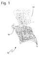
- Fig. 1 shows a perspective view of a typical air intake manifold 10.
- Air intake manifold 10 comprises a plurality of shells welded into one assembly; air intake manifold 10 is constructed of multiple runners 12 and plenum 14. Air enters plenum 14 through the throttle body neck 16, to be distributed into runners 12, which feed the air into the engine cylinders (not shown).
- Fig. 2 shows a cross sectional view of a co-injection molded multi-layer air intake manifold shell 20.
- Air intake manifold shell 20 comprises outer layer 22; sound absorbing core 24; and inner layer 26.
- inner layer 26 and/or outer layer 24 comprises a polyamide resin comprising a nylon resin, a high specific gravity filler, optionally a reinforcement fiber and optionally an elastomer.
- the polyamide preferably comprises at least one of nylon 6, nylon 6/6 and nylon 6/66.
- the high specific gravity filler preferably comprises a mineral and/or a metal filler, more preferably at least one of barium sulfate and tungsten.
- the elastomer if present, preferably comprises at least one of functionalized ethylene-propylene copolymer, functionalized styrene-ethylene butadiene-styrene copolymer and metal salt neutralized ethylene methylacrylic acid di- and ter-polymers.
- the reinforcement fiber if present, preferably comprises at least one of glass fibers, carbon fibers and steel fibers.
- the polyamide is present in an amount of from about 20 to about 45 wt. % and the high specific gravity filler ranges from about 40 to about 70 wt. %.
- the reinforcement fiber may be present in amounts up to about 30 wt. % and the elastomer ranges up to about 10 wt. %.
- Capron® XA2935 resin containing glass fibers and mineral filler.
- the mineral filler has a specific gravity in the range of 4 - 20, such as barium sulfate or tungsten.
- barium sulfate is present in an amount substantially equal to about 53 % by weight, and the amount of the glass fiber reinforcement is substantially equal to about 15% by weight.
- Core 24 is alternatively comprised of a low-density material, such as a polyamide resin, having a foam structure.
- the foam structure can be either open- or closed-cell in nature, and produced by either chemical or physical blowing agent(s), known in the art, introduced into the polyamide resin either in the pellet or melt state.
- the foam cell structure would have an average diameter range of from the order of one micron (i.e. via MuCell process) to as large as one centimeter.
- the range in reduction of density of the polyamide resin as a result of the foaming process would be 10 to 70%.
- core 24 is comprised of a high damping elastomer, such as specific types of thermoplastic elastomers and thermoplastic polyurethanes available commercially, which are capable of being co-injection molded with the polyamide resin.
- a high damping elastomer found to be especially well suited for use as core layer is a polyamide-based Santoprene, used alone or in-combination with high damping 'carbon nanotubes'.
- the section of the air intake manifold shell shown generally at 30 in Figure 3 , is provided with a plurality of blisters 38 to distribute localized increased core thickness at predetermined locations over air intake manifold shell 30.
- a plurality of blisters 38 to distribute localized increased core thickness at predetermined locations over air intake manifold shell 30.
- Such an arrangement of blisters 38 an air intake manifold shell 30 increases the mass effect.
- the locations are selected to increase noise transmission losses. Noise is reduced by shifting the local natural frequencies away from the input driving frequency domain and lowering the frequency by adding lumped mass.
- the location and the number of the distributed masses or blisters can be optimized based an the locus and amplitude of noise appointed to be filtered out.
- the air intake manifold shell thickness is not uniform. Air intake manifold shell portions having increased thickness are positioned over predetermined areas to increase noise transmission losses by increasing the mass effect. Each of the locations is selected to maximize noise attenuation over larger amplitude transmission points, thereby providing increased noise transmission losses over substantially the entire surface area of the air intake
- the air intake manifold shell This arrangement of the thicker air intake manifold shell portions reduces noise by shifting the local natural frequencies away from the input driving frequency domain and lowering the frequency by adding lumped mass. Tailoring the location and the number of the distributed masses permits optimum noise attenuation for a given air intake manifold weight, size and thickness.
- the air intake manifold can be constructed economically using a minimum of material, and is small, light, efficient, and highly reliable in operation.
Landscapes
- Engineering & Computer Science (AREA)
- Chemical & Material Sciences (AREA)
- Combustion & Propulsion (AREA)
- Mechanical Engineering (AREA)
- General Engineering & Computer Science (AREA)
- Manufacturing & Machinery (AREA)
- Laminated Bodies (AREA)
- Soundproofing, Sound Blocking, And Sound Damping (AREA)
- Cylinder Crankcases Of Internal Combustion Engines (AREA)
- Exhaust Silencers (AREA)
- Injection Moulding Of Plastics Or The Like (AREA)
- Characterised By The Charging Evacuation (AREA)
Claims (12)
- Coquille multicouches de collecteur d'admission d'air de moteur (20), comprenant :a. une couche extérieure (22) ;b. une âme absorbant le bruit (24) ; etc. une couche intérieure (26)au moins une desdites couches intérieure et extérieure (26, 22) comprend une résine polyamide, ladite résine polyamide comprend une matière de charge à haute densité et des fibres de verre servant au renforcement, et ladite résine polyamide comprend en outre un élastomère, qui comprend au moins un parmi les copolymères éthylène-propylène fonctionnalisé, styrène-éthylène butylène-styrène fonctionnalisé et di- et ter-polymères éthylène acide méthylacrylique neutralisés par des sels métalliques.
- Coquille de collecteur d'admission d'air (20), selon la revendication 1, dans laquelle ledit élastomère est présent dans une quantité d'environ 10 % en poids du poids combiné de ladite résine polyamide et dudit élastomère.
- Coquille de collecteur d'admission d'air (20), selon la revendication 1 ou 2, dans laquelle ladite matière de charge comprend une matière de charge minérale et/ou métallique.
- Coquille de collecteur d'admission d'air (20), selon l'une quelconque des revendications 1 à 3, dans laquelle ladite matière de charge comprend au moins un parmi le sulfate de baryum et le tungstène.
- Coquille de collecteur d'admission d'air (20), selon l'une quelconque des revendications 1 à 4, dans laquelle la quantité de ladite matière de charge à haute densité comprend d'environ 40 à environ 70 % en poids du poids combiné de ladite résine polyamide et de ladite matière de charge.
- Coquille de collecteur d'admission d'air (20), selon l'une quelconque des revendications 1 à 5, dans laquelle ledit renforcement comprend de la fibre de verre présente dans une quantité pouvant aller jusqu'à environ 30 % en poids du poids combiné de ladite résine polyamide et de ladite fibre de verre.
- Coquille de collecteur d'admission d'air (20), selon l'une quelconque des revendications 1 à 6, dans laquelle au moins une desdites couches intérieure et extérieure (26, 22) est formée par une composition comprenant une résine polyamide, constituée d'un parmi le nylon 6, le nylon 6/6 et le nylon 6/66.
- Coquille de collecteur d'admission d'air (20), selon l'une quelconque des revendications 1 à 7, dans laquelle ladite âme (24) est constituée d'un matériau à haute densité.
- Coquille de collecteur d'admission d'air (20), selon l'une quelconque des revendications 1 à 8, dans laquelle ladite âme (24) est constituée d'une structure en mousse.
- Coquille de collecteur d'admission d'air (20), selon l'une quelconque des revendications 1 à 9, dans laquelle ladite structure en mousse est constituée d'une résine polyamide sous forme de mousse.
- Coquille de collecteur d'admission d'air (20), selon l'une quelconque des revendications 1 à 10, dans laquelle ladite âme (24) est constituée d'un élastomère ayant des caractéristiques d'amortissement élevées.
- Coquille multicouches de collecteur d'admission d'air de moteur (20) selon l'une quelconque des revendications 1 à 11, dans laquelle lesdites couches (26, 22) sont pourvues d'une pluralité de bulles (38).
Applications Claiming Priority (3)
| Application Number | Priority Date | Filing Date | Title |
|---|---|---|---|
| US09/960,157 US6705268B2 (en) | 2001-09-21 | 2001-09-21 | Engine noise barrier |
| US960157 | 2001-09-21 | ||
| PCT/US2002/029752 WO2003027479A1 (fr) | 2001-09-21 | 2002-09-19 | Tubulure d'admission de moteur fabriquee dans une matiere composite antibruit |
Publications (2)
| Publication Number | Publication Date |
|---|---|
| EP1430215A1 EP1430215A1 (fr) | 2004-06-23 |
| EP1430215B1 true EP1430215B1 (fr) | 2008-11-12 |
Family
ID=25502867
Family Applications (1)
| Application Number | Title | Priority Date | Filing Date |
|---|---|---|---|
| EP02775876A Expired - Lifetime EP1430215B1 (fr) | 2001-09-21 | 2002-09-19 | Tubulure d'admission de moteur fabriquee dans une matiere composite antibruit |
Country Status (9)
| Country | Link |
|---|---|
| US (1) | US6705268B2 (fr) |
| EP (1) | EP1430215B1 (fr) |
| JP (1) | JP2005504907A (fr) |
| CN (1) | CN100394017C (fr) |
| AT (1) | ATE414222T1 (fr) |
| CA (1) | CA2460531A1 (fr) |
| DE (1) | DE60229865D1 (fr) |
| MX (1) | MXPA04002469A (fr) |
| WO (1) | WO2003027479A1 (fr) |
Cited By (1)
| Publication number | Priority date | Publication date | Assignee | Title |
|---|---|---|---|---|
| US9464607B2 (en) | 2014-10-28 | 2016-10-11 | Ford Global Technologies, Llc | Integrally-molded intake manifold connector for engine cover of combustion engine |
Families Citing this family (19)
| Publication number | Priority date | Publication date | Assignee | Title |
|---|---|---|---|---|
| DE10323527B4 (de) * | 2003-05-24 | 2009-04-16 | Danfoss Compressors Gmbh | Kältemittelkompressor |
| WO2004106053A1 (fr) * | 2003-05-29 | 2004-12-09 | E. I. Du Pont De Nemours And Company | Collecteurs d'admission d'air et autres structures de materiaux polymeres rigides et alveoles a transmission de bruit reduite et leurs procedes de preparation |
| DE102004049791A1 (de) * | 2004-10-12 | 2006-04-13 | Mann+Hummel Gmbh | Ansaugsystem einer Brennkraftmaschine |
| US7395790B2 (en) * | 2004-11-18 | 2008-07-08 | S&S Cycle, Inc. | Reed valve breather for evolution engine |
| US20060289231A1 (en) * | 2005-06-28 | 2006-12-28 | Priebe Joseph A | Acoustic absorber/barrier composite |
| ITRM20050429A1 (it) * | 2005-08-05 | 2007-02-06 | Adler Plastic S P A | Pannello di isolamento. |
| KR101723250B1 (ko) | 2008-12-23 | 2017-04-04 | 쓰리엠 이노베이티브 프로퍼티즈 컴파니 | 운송 차량 차음 방법 및 장치 |
| JP2012513288A (ja) | 2008-12-23 | 2012-06-14 | スリーエム イノベイティブ プロパティズ カンパニー | 聴覚保護方法及び装置 |
| WO2010151533A2 (fr) | 2009-06-25 | 2010-12-29 | 3M Innovative Properties Company | Barrière sonore pour gestion de fréquence acoustique audible |
| US20110100315A1 (en) * | 2009-10-31 | 2011-05-05 | Mann+Hummel Gmbh | Intake manifold with integrated sound barrier |
| CN103104384B (zh) * | 2011-11-10 | 2015-11-18 | 北汽福田汽车股份有限公司 | 发动机进气管、发动机进气系统以及汽车 |
| DE102012221488A1 (de) * | 2012-11-23 | 2014-05-28 | Mahle International Gmbh | Luftführendes Bauteil einer Frischluftanlage |
| CN103903608B (zh) * | 2012-12-27 | 2018-12-25 | 浙江艾迪雅汽车部件新材料有限公司 | 一种高效隔音材料及其制作方法 |
| KR101496035B1 (ko) | 2013-09-27 | 2015-02-26 | 지엠 글로벌 테크놀러지 오퍼레이션스 엘엘씨 | 인슐레이션 일체형 흡기 매니폴드 |
| DE102013113214A1 (de) * | 2013-11-29 | 2015-06-03 | Dr. Ing. H.C. F. Porsche Aktiengesellschaft | Sauganordnung für einen Verbrennungsmotor |
| DE102015215394A1 (de) | 2015-08-12 | 2017-02-16 | Etm Engineering Technologie Marketing Gmbh | Luftleitungsrohr für den Ansaugtrakt eines Verbrennungsmotors |
| US11034819B2 (en) | 2016-02-24 | 2021-06-15 | Exxonmobil Chemical Patents Inc. | Self-assembled propylene-based compositions and methods of production thereof |
| CN107587962B (zh) * | 2017-10-30 | 2023-09-29 | 安徽工业大学 | 一种低阻降噪的间隔式空气滤清器 |
| CN110360031B (zh) * | 2019-07-17 | 2020-08-21 | 安徽江淮汽车集团股份有限公司 | 发动机进气加热方法、装置、设备及存储介质 |
Citations (2)
| Publication number | Priority date | Publication date | Assignee | Title |
|---|---|---|---|---|
| US3652360A (en) * | 1965-05-12 | 1972-03-28 | Us Plywood Champ Papers Inc | Method for manufacturing mass particles in a viscoelastic matrix |
| EP0251645A2 (fr) * | 1986-06-23 | 1988-01-07 | NIPPON MINING & METALS COMPANY, LIMITED | Matériel isolant contre le bruit et reduisant la formation de la fumée |
Family Cites Families (29)
| Publication number | Priority date | Publication date | Assignee | Title |
|---|---|---|---|---|
| JPS5311248A (en) * | 1976-07-19 | 1978-02-01 | Kawasaki Heavy Ind Ltd | Engine cover |
| DE3814955A1 (de) * | 1988-05-03 | 1989-11-16 | Freudenberg Carl Fa | Ansaugverteiler |
| JPH02181063A (ja) | 1989-02-06 | 1990-07-13 | Isuzu Motors Ltd | 内燃機関の吸気マニホールド |
| JP3219407B2 (ja) | 1990-11-26 | 2001-10-15 | エクセル株式会社 | 多層プラスチック管及びその製造方法 |
| JPH04229236A (ja) * | 1990-11-26 | 1992-08-18 | Calsonic Corp | 合成樹脂製管状部材の製造方法及びそれに用いる低融点合金製中子 |
| JP2851715B2 (ja) * | 1991-04-09 | 1999-01-27 | 出光興産株式会社 | 熱可塑性樹脂組成物 |
| JPH05338015A (ja) * | 1992-06-10 | 1993-12-21 | Fuji Heavy Ind Ltd | 中空状樹脂成形品 |
| JP2921287B2 (ja) * | 1992-08-31 | 1999-07-19 | トヨタ自動車株式会社 | 内燃機関の吸気装置 |
| US5354802A (en) | 1993-02-11 | 1994-10-11 | Polyplastics Co., Ltd. | Resin composition for blow molding and blow molded item made therefrom |
| US5530213A (en) * | 1993-05-17 | 1996-06-25 | Ford Motor Company | Sound-deadened motor vehicle exhaust manifold |
| JPH0785908A (ja) * | 1993-09-20 | 1995-03-31 | Sumitomo Wiring Syst Ltd | 点火プラグキャップ |
| US5370087A (en) * | 1993-09-28 | 1994-12-06 | The United States Of America As Represented By The Secretary Of The Navy | Low vibration polymeric composite engine |
| JP3443140B2 (ja) * | 1993-10-04 | 2003-09-02 | 富士重工業株式会社 | 多層プラスチック成形体とその製造方法 |
| US5538571A (en) * | 1993-12-01 | 1996-07-23 | Asahi Tec Corporation | Method of manufacturing hollow resin molding |
| US5400296A (en) | 1994-01-25 | 1995-03-21 | Poiesis Research, Inc. | Acoustic attenuation and vibration damping materials |
| CN1179122A (zh) * | 1995-03-17 | 1998-04-15 | 钴碳化钨硬质合金公司 | 带有补偿切削刃的螺旋切削刀片 |
| FR2734603B1 (fr) * | 1995-05-23 | 1997-07-25 | Magneti Marelli France | Collecteur d'admission a tubes d'air anneles, pour moteur a combustion interne |
| DE19613467A1 (de) * | 1996-04-04 | 1997-10-09 | Mann & Hummel Filter | Ansaugsystem für einen Verbrennungsmotor |
| JP3787915B2 (ja) * | 1996-09-04 | 2006-06-21 | 豊田合成株式会社 | 内燃機関の吸気管 |
| DE59707508D1 (de) * | 1996-11-22 | 2002-07-18 | Denso Corp | Lufteinlass für verbrennungsmotor |
| JP3815520B2 (ja) | 1997-03-31 | 2006-08-30 | 豊田合成株式会社 | インテークマニホールドカバー |
| JP3831467B2 (ja) * | 1997-04-09 | 2006-10-11 | カルソニックカンセイ株式会社 | 合成樹脂製吸気管およびその製造方法 |
| US6077907A (en) | 1997-07-09 | 2000-06-20 | Borealis Ag | Molded polyolefin parts of improved dimensional stability at elevated temperatures and improved stiffness |
| EP0992674A3 (fr) * | 1998-10-08 | 2000-07-19 | Alusuisse Technology & Management AG | Collecteur d'admission |
| EP0997496B1 (fr) * | 1998-10-26 | 2006-03-01 | Toray Industries, Inc. | Compositions de polyamides soudables, leur procédé de préparation et les objets moulés à partirs de cette composition |
| US6116206A (en) * | 1999-05-19 | 2000-09-12 | General Motors Corporation | Intake manifold cover |
| EP1125719B1 (fr) * | 2000-02-14 | 2004-08-04 | Nichias Corporation | Objet en mousse à mémoire de forme et procédé pour sa fabrication |
| JP4467731B2 (ja) * | 2000-08-09 | 2010-05-26 | 富士重工業株式会社 | 樹脂製チャンバの遮音構造 |
| JP3833909B2 (ja) * | 2001-07-11 | 2006-10-18 | 東海ゴム工業株式会社 | 防音カバー |
-
2001
- 2001-09-21 US US09/960,157 patent/US6705268B2/en not_active Expired - Fee Related
-
2002
- 2002-09-19 CA CA002460531A patent/CA2460531A1/fr not_active Abandoned
- 2002-09-19 AT AT02775876T patent/ATE414222T1/de not_active IP Right Cessation
- 2002-09-19 MX MXPA04002469A patent/MXPA04002469A/es unknown
- 2002-09-19 CN CNB028184645A patent/CN100394017C/zh not_active Expired - Fee Related
- 2002-09-19 DE DE60229865T patent/DE60229865D1/de not_active Expired - Lifetime
- 2002-09-19 WO PCT/US2002/029752 patent/WO2003027479A1/fr not_active Ceased
- 2002-09-19 JP JP2003531015A patent/JP2005504907A/ja not_active Withdrawn
- 2002-09-19 EP EP02775876A patent/EP1430215B1/fr not_active Expired - Lifetime
Patent Citations (2)
| Publication number | Priority date | Publication date | Assignee | Title |
|---|---|---|---|---|
| US3652360A (en) * | 1965-05-12 | 1972-03-28 | Us Plywood Champ Papers Inc | Method for manufacturing mass particles in a viscoelastic matrix |
| EP0251645A2 (fr) * | 1986-06-23 | 1988-01-07 | NIPPON MINING & METALS COMPANY, LIMITED | Matériel isolant contre le bruit et reduisant la formation de la fumée |
Cited By (1)
| Publication number | Priority date | Publication date | Assignee | Title |
|---|---|---|---|---|
| US9464607B2 (en) | 2014-10-28 | 2016-10-11 | Ford Global Technologies, Llc | Integrally-molded intake manifold connector for engine cover of combustion engine |
Also Published As
| Publication number | Publication date |
|---|---|
| JP2005504907A (ja) | 2005-02-17 |
| WO2003027479A1 (fr) | 2003-04-03 |
| DE60229865D1 (de) | 2008-12-24 |
| ATE414222T1 (de) | 2008-11-15 |
| CA2460531A1 (fr) | 2003-04-03 |
| EP1430215A1 (fr) | 2004-06-23 |
| US6705268B2 (en) | 2004-03-16 |
| MXPA04002469A (es) | 2004-05-31 |
| US20030062012A1 (en) | 2003-04-03 |
| CN1556895A (zh) | 2004-12-22 |
| CN100394017C (zh) | 2008-06-11 |
Similar Documents
| Publication | Publication Date | Title |
|---|---|---|
| EP1430215B1 (fr) | Tubulure d'admission de moteur fabriquee dans une matiere composite antibruit | |
| EP1570461B1 (fr) | Composite de garniture ultraleger | |
| US20090242095A1 (en) | System for reducing acoustic energy | |
| CN1243481A (zh) | 带隔离器的隔音板 | |
| KR20130110234A (ko) | 음향 및 열에 대한 효과적인 절연재 | |
| WO2002083461A1 (fr) | Panneau insonorisant et son utilisation dans l'insonorisation de vehicules | |
| CN103534750A (zh) | 汽车噪声衰减装饰部件 | |
| WO2007134391A1 (fr) | Écran acoustique | |
| RU2405216C2 (ru) | Слоистая конструкция, имеющая частотно-избирательные характеристики двойной степени | |
| RU2639759C2 (ru) | Комбинированная звукопоглощающая панель | |
| EP3531415B1 (fr) | Structure d'insonorisation et procédé de fabrication de structure d'insonorisation | |
| RU2716043C1 (ru) | Низкошумное техническое помещение | |
| RU2504488C1 (ru) | Транспортное средство | |
| CN114044013A (zh) | 一种局域共振系统及减震降噪车体型材板件 | |
| JP2008203542A (ja) | 吸音体 | |
| AU2002341726A1 (en) | Engine intake manifold made of noise barrier composit material | |
| Wentzel et al. | Empirically predicting the sound transmission loss of double-wall sound barrier assemblies | |
| JPH03293409A (ja) | 吸遮音防音パネル | |
| CN210087179U (zh) | 一种具有隔音功能的门芯真空填充板 | |
| KR101033395B1 (ko) | 자동차용 흡음재 | |
| JPH06332466A (ja) | 車両外装用吸音材 | |
| KR20040081520A (ko) | 자동차용 플로우카페트 흡음재 | |
| CN219886598U (zh) | 一种微孔金属吸声体 | |
| KR20250141306A (ko) | 전기자동차용 엔진룸 격벽 | |
| KR100706352B1 (ko) | 자동차용 흡음재 |
Legal Events
| Date | Code | Title | Description |
|---|---|---|---|
| PUAI | Public reference made under article 153(3) epc to a published international application that has entered the european phase |
Free format text: ORIGINAL CODE: 0009012 |
|
| 17P | Request for examination filed |
Effective date: 20040421 |
|
| AK | Designated contracting states |
Kind code of ref document: A1 Designated state(s): AT BE BG CH CY CZ DE DK EE ES FI FR GB GR IE IT LI LU MC NL PT SE SK TR |
|
| AX | Request for extension of the european patent |
Extension state: AL LT LV MK RO SI |
|
| 17Q | First examination report despatched |
Effective date: 20061206 |
|
| 17Q | First examination report despatched |
Effective date: 20061206 |
|
| RAP1 | Party data changed (applicant data changed or rights of an application transferred) |
Owner name: BASF SE |
|
| GRAP | Despatch of communication of intention to grant a patent |
Free format text: ORIGINAL CODE: EPIDOSNIGR1 |
|
| GRAS | Grant fee paid |
Free format text: ORIGINAL CODE: EPIDOSNIGR3 |
|
| GRAA | (expected) grant |
Free format text: ORIGINAL CODE: 0009210 |
|
| AK | Designated contracting states |
Kind code of ref document: B1 Designated state(s): AT BE BG CH CY CZ DE DK EE ES FI FR GB GR IE IT LI LU MC NL PT SE SK TR |
|
| REG | Reference to a national code |
Ref country code: GB Ref legal event code: FG4D |
|
| REG | Reference to a national code |
Ref country code: CH Ref legal event code: EP |
|
| REG | Reference to a national code |
Ref country code: IE Ref legal event code: FG4D |
|
| REF | Corresponds to: |
Ref document number: 60229865 Country of ref document: DE Date of ref document: 20081224 Kind code of ref document: P |
|
| PG25 | Lapsed in a contracting state [announced via postgrant information from national office to epo] |
Ref country code: ES Free format text: LAPSE BECAUSE OF FAILURE TO SUBMIT A TRANSLATION OF THE DESCRIPTION OR TO PAY THE FEE WITHIN THE PRESCRIBED TIME-LIMIT Effective date: 20090223 Ref country code: AT Free format text: LAPSE BECAUSE OF FAILURE TO SUBMIT A TRANSLATION OF THE DESCRIPTION OR TO PAY THE FEE WITHIN THE PRESCRIBED TIME-LIMIT Effective date: 20081112 |
|
| NLV1 | Nl: lapsed or annulled due to failure to fulfill the requirements of art. 29p and 29m of the patents act | ||
| PG25 | Lapsed in a contracting state [announced via postgrant information from national office to epo] |
Ref country code: NL Free format text: LAPSE BECAUSE OF FAILURE TO SUBMIT A TRANSLATION OF THE DESCRIPTION OR TO PAY THE FEE WITHIN THE PRESCRIBED TIME-LIMIT Effective date: 20081112 Ref country code: FI Free format text: LAPSE BECAUSE OF FAILURE TO SUBMIT A TRANSLATION OF THE DESCRIPTION OR TO PAY THE FEE WITHIN THE PRESCRIBED TIME-LIMIT Effective date: 20081112 |
|
| PG25 | Lapsed in a contracting state [announced via postgrant information from national office to epo] |
Ref country code: BG Free format text: LAPSE BECAUSE OF FAILURE TO SUBMIT A TRANSLATION OF THE DESCRIPTION OR TO PAY THE FEE WITHIN THE PRESCRIBED TIME-LIMIT Effective date: 20090212 Ref country code: BE Free format text: LAPSE BECAUSE OF FAILURE TO SUBMIT A TRANSLATION OF THE DESCRIPTION OR TO PAY THE FEE WITHIN THE PRESCRIBED TIME-LIMIT Effective date: 20081112 Ref country code: EE Free format text: LAPSE BECAUSE OF FAILURE TO SUBMIT A TRANSLATION OF THE DESCRIPTION OR TO PAY THE FEE WITHIN THE PRESCRIBED TIME-LIMIT Effective date: 20081112 Ref country code: DK Free format text: LAPSE BECAUSE OF FAILURE TO SUBMIT A TRANSLATION OF THE DESCRIPTION OR TO PAY THE FEE WITHIN THE PRESCRIBED TIME-LIMIT Effective date: 20081112 |
|
| PG25 | Lapsed in a contracting state [announced via postgrant information from national office to epo] |
Ref country code: PT Free format text: LAPSE BECAUSE OF FAILURE TO SUBMIT A TRANSLATION OF THE DESCRIPTION OR TO PAY THE FEE WITHIN THE PRESCRIBED TIME-LIMIT Effective date: 20090413 Ref country code: SE Free format text: LAPSE BECAUSE OF FAILURE TO SUBMIT A TRANSLATION OF THE DESCRIPTION OR TO PAY THE FEE WITHIN THE PRESCRIBED TIME-LIMIT Effective date: 20090212 Ref country code: CZ Free format text: LAPSE BECAUSE OF FAILURE TO SUBMIT A TRANSLATION OF THE DESCRIPTION OR TO PAY THE FEE WITHIN THE PRESCRIBED TIME-LIMIT Effective date: 20081112 |
|
| PLBE | No opposition filed within time limit |
Free format text: ORIGINAL CODE: 0009261 |
|
| STAA | Information on the status of an ep patent application or granted ep patent |
Free format text: STATUS: NO OPPOSITION FILED WITHIN TIME LIMIT |
|
| PG25 | Lapsed in a contracting state [announced via postgrant information from national office to epo] |
Ref country code: SK Free format text: LAPSE BECAUSE OF FAILURE TO SUBMIT A TRANSLATION OF THE DESCRIPTION OR TO PAY THE FEE WITHIN THE PRESCRIBED TIME-LIMIT Effective date: 20081112 |
|
| 26N | No opposition filed |
Effective date: 20090813 |
|
| PG25 | Lapsed in a contracting state [announced via postgrant information from national office to epo] |
Ref country code: MC Free format text: LAPSE BECAUSE OF NON-PAYMENT OF DUE FEES Effective date: 20090930 |
|
| GBPC | Gb: european patent ceased through non-payment of renewal fee |
Effective date: 20090919 |
|
| REG | Reference to a national code |
Ref country code: IE Ref legal event code: MM4A |
|
| REG | Reference to a national code |
Ref country code: FR Ref legal event code: ST Effective date: 20100531 |
|
| PG25 | Lapsed in a contracting state [announced via postgrant information from national office to epo] |
Ref country code: FR Free format text: LAPSE BECAUSE OF NON-PAYMENT OF DUE FEES Effective date: 20090930 Ref country code: IE Free format text: LAPSE BECAUSE OF NON-PAYMENT OF DUE FEES Effective date: 20090919 |
|
| PG25 | Lapsed in a contracting state [announced via postgrant information from national office to epo] |
Ref country code: GR Free format text: LAPSE BECAUSE OF FAILURE TO SUBMIT A TRANSLATION OF THE DESCRIPTION OR TO PAY THE FEE WITHIN THE PRESCRIBED TIME-LIMIT Effective date: 20090213 |
|
| PGFP | Annual fee paid to national office [announced via postgrant information from national office to epo] |
Ref country code: CH Payment date: 20100930 Year of fee payment: 9 |
|
| PG25 | Lapsed in a contracting state [announced via postgrant information from national office to epo] |
Ref country code: GB Free format text: LAPSE BECAUSE OF NON-PAYMENT OF DUE FEES Effective date: 20090919 |
|
| PGFP | Annual fee paid to national office [announced via postgrant information from national office to epo] |
Ref country code: LU Payment date: 20100927 Year of fee payment: 9 |
|
| PGFP | Annual fee paid to national office [announced via postgrant information from national office to epo] |
Ref country code: DE Payment date: 20101129 Year of fee payment: 9 |
|
| PG25 | Lapsed in a contracting state [announced via postgrant information from national office to epo] |
Ref country code: IT Free format text: LAPSE BECAUSE OF FAILURE TO SUBMIT A TRANSLATION OF THE DESCRIPTION OR TO PAY THE FEE WITHIN THE PRESCRIBED TIME-LIMIT Effective date: 20081112 |
|
| PG25 | Lapsed in a contracting state [announced via postgrant information from national office to epo] |
Ref country code: TR Free format text: LAPSE BECAUSE OF FAILURE TO SUBMIT A TRANSLATION OF THE DESCRIPTION OR TO PAY THE FEE WITHIN THE PRESCRIBED TIME-LIMIT Effective date: 20081112 |
|
| PG25 | Lapsed in a contracting state [announced via postgrant information from national office to epo] |
Ref country code: CY Free format text: LAPSE BECAUSE OF FAILURE TO SUBMIT A TRANSLATION OF THE DESCRIPTION OR TO PAY THE FEE WITHIN THE PRESCRIBED TIME-LIMIT Effective date: 20081112 |
|
| REG | Reference to a national code |
Ref country code: CH Ref legal event code: PL |
|
| REG | Reference to a national code |
Ref country code: DE Ref legal event code: R119 Ref document number: 60229865 Country of ref document: DE Effective date: 20120403 |
|
| PG25 | Lapsed in a contracting state [announced via postgrant information from national office to epo] |
Ref country code: CH Free format text: LAPSE BECAUSE OF NON-PAYMENT OF DUE FEES Effective date: 20110930 Ref country code: DE Free format text: LAPSE BECAUSE OF NON-PAYMENT OF DUE FEES Effective date: 20120403 Ref country code: LI Free format text: LAPSE BECAUSE OF NON-PAYMENT OF DUE FEES Effective date: 20110930 |
|
| PG25 | Lapsed in a contracting state [announced via postgrant information from national office to epo] |
Ref country code: LU Free format text: LAPSE BECAUSE OF NON-PAYMENT OF DUE FEES Effective date: 20110919 |