EP1431186B1 - Machine d'emballage pour des articles fragiles, plats ou en forme de disque - Google Patents
Machine d'emballage pour des articles fragiles, plats ou en forme de disque Download PDFInfo
- Publication number
- EP1431186B1 EP1431186B1 EP03029319A EP03029319A EP1431186B1 EP 1431186 B1 EP1431186 B1 EP 1431186B1 EP 03029319 A EP03029319 A EP 03029319A EP 03029319 A EP03029319 A EP 03029319A EP 1431186 B1 EP1431186 B1 EP 1431186B1
- Authority
- EP
- European Patent Office
- Prior art keywords
- stacking
- drive
- objects
- packaging machine
- stack
- Prior art date
- Legal status (The legal status is an assumption and is not a legal conclusion. Google has not performed a legal analysis and makes no representation as to the accuracy of the status listed.)
- Expired - Lifetime
Links
- 238000004806 packaging method and process Methods 0.000 title claims description 22
- 235000014594 pastries Nutrition 0.000 claims abstract 2
- 230000015572 biosynthetic process Effects 0.000 claims description 7
- 238000006073 displacement reaction Methods 0.000 claims description 7
- 238000012546 transfer Methods 0.000 claims description 7
- 230000002441 reversible effect Effects 0.000 claims description 2
- 210000000056 organ Anatomy 0.000 claims 3
- 230000001360 synchronised effect Effects 0.000 claims 2
- 238000000034 method Methods 0.000 claims 1
- 238000012856 packing Methods 0.000 abstract 1
- 238000013461 design Methods 0.000 description 3
- 235000015173 baked goods and baking mixes Nutrition 0.000 description 2
- 238000010276 construction Methods 0.000 description 2
- 235000013611 frozen food Nutrition 0.000 description 2
- 230000002093 peripheral effect Effects 0.000 description 2
- 230000001133 acceleration Effects 0.000 description 1
- 230000004323 axial length Effects 0.000 description 1
- 230000008878 coupling Effects 0.000 description 1
- 238000010168 coupling process Methods 0.000 description 1
- 238000005859 coupling reaction Methods 0.000 description 1
- 238000011161 development Methods 0.000 description 1
- 230000018109 developmental process Effects 0.000 description 1
- 235000012470 frozen dough Nutrition 0.000 description 1
- 238000003384 imaging method Methods 0.000 description 1
- 238000004519 manufacturing process Methods 0.000 description 1
- 238000005259 measurement Methods 0.000 description 1
- 238000001465 metallisation Methods 0.000 description 1
- 238000010257 thawing Methods 0.000 description 1
- 238000012549 training Methods 0.000 description 1
- 230000007704 transition Effects 0.000 description 1
Images

Classifications
-
- B—PERFORMING OPERATIONS; TRANSPORTING
- B65—CONVEYING; PACKING; STORING; HANDLING THIN OR FILAMENTARY MATERIAL
- B65B—MACHINES, APPARATUS OR DEVICES FOR, OR METHODS OF, PACKAGING ARTICLES OR MATERIALS; UNPACKING
- B65B35/00—Supplying, feeding, arranging or orientating articles to be packaged
- B65B35/30—Arranging and feeding articles in groups
- B65B35/50—Stacking one article, or group of articles, upon another before packaging
-
- B—PERFORMING OPERATIONS; TRANSPORTING
- B65—CONVEYING; PACKING; STORING; HANDLING THIN OR FILAMENTARY MATERIAL
- B65B—MACHINES, APPARATUS OR DEVICES FOR, OR METHODS OF, PACKAGING ARTICLES OR MATERIALS; UNPACKING
- B65B23/00—Packaging fragile or shock-sensitive articles other than bottles; Unpacking eggs
- B65B23/10—Packaging biscuits
-
- B—PERFORMING OPERATIONS; TRANSPORTING
- B65—CONVEYING; PACKING; STORING; HANDLING THIN OR FILAMENTARY MATERIAL
- B65B—MACHINES, APPARATUS OR DEVICES FOR, OR METHODS OF, PACKAGING ARTICLES OR MATERIALS; UNPACKING
- B65B5/00—Packaging individual articles in containers or receptacles, e.g. bags, sacks, boxes, cartons, cans, jars
- B65B5/06—Packaging groups of articles, the groups being treated as single articles
Definitions
- the invention relates to a packaging machine for fragile, flat or disc-shaped objects, in particular frozen dough pieces, frozen food pieces, baked goods and the like.
- the articles to be packaged are conveyed substantially horizontally in a row towards a stacking device, the latter being intended to form vertical stacks of a certain number of superimposed objects.
- the feed device in the form of an endless, guided by rollers conveyor belt or more endless, guided by rollers conveyors throws the objects to be stacked in a contour of the objects in cross-section adapted, provided with a vertical slot stacking shaft each on a stack underlay, which Beginning of the formation of a stack is located at the top of the stacking shaft and is moved downwards as the height of the forming stack in the stacking shaft, the respective stack support via a boom with a vertical drive arrangement for moving down a stack support within the stacking shaft on the reaching through the slot of the stacking shaft Boom, and is connected for upward movement in a return movement outside of the stacking shaft.
- the stacking shaft is supported fixed to the frame in such a way that its upper end is freely accessible for pivoting in a stack underlay for the purpose of subsequent downward movement, and further the lower end of the stacking shaft for swiveling out a stack underlay after formation of the stack of objects is also freely accessible.
- a stack support reaches the lower end of the stacking shaft and is pivoted away from the lower end of the stacking shaft, so the formed stack of objects from the stacking shaft slides down to a take-down lowerable Stapelabdgingvorraum, wherein between the stacking device and the Stapelabdgingvortechnisch a wrapping device is provided which in particular provides collapsed bags or bags into which the formed stacks of objects are placed under rest on the stack removal device and are finally supplied to further conveying means while the removal device is moved downwards.
- the speed of operation of packaging machines of the type considered here must be set relatively high, especially when deep-frozen items to be processed and packaged, otherwise thawing of the items is to be feared, so that either no longer manageable or no longer usable and are usable.
- the invention enables the problem to be solved, a packaging machine with the features of the preamble of claim 1 in such a way that a high operating speed can be achieved that stack arbitrarily adjustable height can be formed and that the objects to be handled can be stacked gently stacking.
- the respective height of the stack formed depends on a corresponding control of the separately variable speed controllable drive devices and can be programmed in a central control unit.
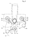
- Fig. 1 omitting certain parts for ease of illustration, and in certain details only schematically reproduced Verpakkungsmaschine includes a feed device with a portion or more sections endlessly circulating, guided by rollers 1 conveyor belts 2, wherein one of the rollers 1 with a not shown , intermittent or continuously operated drive is coupled.
- On the upper run of the conveyor belt 2 are disk-shaped objects 3, for example, circular-shaped deep-frozen dough pieces, frozen food pieces, baked goods and the like.
- the conveyor belt 2 conveys the articles 3 in the direction of a circular discharge opening 6 in the present case in a horizontal upper housing cover 7 of the packaging machine, wherein funnel-like guide surfaces, not shown, may be provided at the edges of the discharge opening 6 in FIG. that dropped from the conveyor belt 2 objects 3 fall safely through the discharge opening 6.
- a lower housing cover 8 At a certain distance below the horizontal housing cover 7 is a lower housing cover 8, in which a vertically aligned with the discharge opening 6 transfer opening 9 is provided.
- the cross-section of the interior of the stacking shaft 11 is adapted to the outline shape of the objects 3 to be stacked and is substantially circular in the present example.
- the stack support 29 held on the boom 27 through the slot 10 of the stacking shaft 11 is already near the lower end of the stacking shaft 11 in the operating state shown in FIG. 1 and carries a stack of articles 3 in a desired number or in a desired one Height. While the stack support 28 is moved relatively slowly downward by the drive device or the lifting and lowering drive 14 during the construction of the stack, the stack support 29 moves relatively quickly with the already finished stack formed in this phase of operation by appropriate control of the motor 23rd on a residual path downwards and the stack support 29, the boom 27 and the drive device 15 are pivoted by appropriate control of the rotary drive at the location of the pivot bearing 18 relatively quickly with respect to a clockwise view, so that then at the bottom of the stacking shaft 11, the stack support 29 can be swung out under the stacking shaft 11 and under the bottom of the formed finished rod, in which case the finished stack falls through the transfer opening or passage opening 9 of the housing cover 8 in a bag or a bag on the stack removal device.
- Fig. 1 shows no details of the stack removal device, which together with a wrapping device or Eintütungsvoriques in a below the housing cover 8 located housing 30 is located. For this purpose, the wrapped or packaged stacks are conveyed out by means of a discharge device 31.
- the rotary actuators within the pivot bearings 16, 17, 18 and 19, as well as the drive motors 22 and 23 for the toothed belts of the lifting and lowering drives 20 and 21 may be formed as stepper motors, which are pulsed in such a way that both with respect to the pivoting movements of the drive devices 14 and 15, as well as with respect to the up and down movements of the stacking pads 28 and 29 gentle acceleration or deceleration transition phases between movement sections of greatly different movement speed can be provided. This causes a particularly gentle handling of the objects to be stacked 3 and a trouble-free operation even at relatively high speeds of up to 6000 handled objects per hour.
- the cantilevers 26a, 26b and 26c are driven by the lifting and lowering drives through the slot 10 of the stacking shaft 11 pass through to the respective associated stacking documents. Further, by appropriate radial dimensioning of the cantilever arms and by arranging the axes of rotation 32a, 32b and 32c care is taken that, with respect to the plan view of Fig.
- stacking pads 28a, 28b and 28c has the advantage of further increasing the operating speed and even gentler handling of the articles to be stacked, wherein in a vertically comparatively long stacking well 11 during the formation of a stack of articles at the top of the stacking shaft a ready formed stack of articles for transfer at the same time the stack removal device is underway at the bottom end of the stacking shaft.
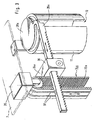
- a horizontal displacement drive 36 which within the drive member 24x of the stroke 3 and is shown only schematically in Fig., It is expressly emphasized that the formation of this Horizontalverschiebungsantriebs 36 can be done in detail in many ways and may also include shear drives, which are actuated by suitable drive means ,
- the cantilever arm 26x is formed in a certain section as a rack, in which a pinion it horizontal displacement drive 36 engages.
- the horizontal displacement drive 36 is supplied via metallization pads 37 on the outer surface of the toothed belt 20x and via sliding contacts with control signals or with energy.
- three stack supports and associated lifting and lowering drives with respective horizontal displacement drives can be associated with a stacking well, with the limitations discussed with respect to FIG Arrangement of the individual lifting and lowering drives in the embodiment of FIG. 3 only to a lesser extent. It is therefore possible, when using the design principles of FIG. 3 a single vertically very elongated stacking shaft also assign more than three stacking documents with associated lifting and lowering drives, whereby the designer with respect to the adjustability of the height of each stack to be formed, with respect to the working speed and in terms of handling the objects to be stacked even greater latitude is given.
Landscapes
- Engineering & Computer Science (AREA)
- Mechanical Engineering (AREA)
- Wrappers (AREA)
Claims (7)
- Machine d'emballage pour des objets (3) fragiles, plats ou en forme de disque, en particulier des pâtons congelés, des produits alimentaires congelés, des produits de boulangerie et similaires,- avec un dispositif d'alimentation (2) pour transporter une suite d'objets (3) dans un plan d'alimentation ;- avec un dispositif d'empilage pour former des piles verticales à partir d'un nombre déterminé d'objets (3) superposés ;- dans lequel le dispositif d'empilage présentant une tour d'empilage (11) munie d'une fente verticale (10) et dont la section transversale est adaptée au contour des objets (3), et des supports de pile (28, 29 ; 28a, 28b, 28c ; 28x) guidés dans la tour vers le bas et à l'extérieur de celle-ci vers le haut, qui sont couplés au moyen d'un ensemble d'entraînement (14, 15 ; 14a, 14b, 14c ; 14x) pour générer les mouvements verticaux des supports de pile ; et- dans lequel la tour d'empilage (11) présentant au niveau de ses extrémités supérieure et inférieure une forme accessible librement par les supports de pile ;- avec un dispositif d'enlèvement de pile disposé en dessous du dispositif d'empilage et mobile verticalement vers le haut ou vers le bas ; et- avec un dispositif de gainage disposé entre le dispositif d'empilage et le dispositif d'enlèvement de pile, qui fournit en particulier des sacs ou des sachets aplatis et dans lequel les piles d'objets (3) formées sont placées en appui sur le dispositif d'enlèvement de pile et introduites dans les sacs ou sachets par un mouvement vers le bas du dispositif d'enlèvement de pile ;- caractérisée en ce que l'ensemble d'entraînement (14, 15 ; 14a, 14b, 14c ; 14x) du dispositif d'empilage présente au moins deux dispositifs d'entraînement (14, 15) associés respectivement à un support de pile et pouvant être commandés séparément à vitesse variable, ou au moins trois dispositifs d'entraînement (14a, 14b, 14c ; 14x) associés respectivement à un support de pile (28a, 28b, 28c ; 28x) et pouvant de préférence être commandés séparément à vitesse variable.
- Machine d'emballage selon la revendication 1, caractérisée en ce que chaque dispositif d'entraînement présente un entraînement de levage et de descente (14, 15 ; 14a, 14b, 14c ; 14x) réversible disposé entre des ponts de boîtier (7, 8) horizontaux solidaires du bâti, qui présentent respectivement un organe d'entraînement (24, 25 ; 24x) qui est relié par un bras (26, 27 ; 26a, 26b, 26c ; 26x) à respectivement un support de pile (28, 29 ; 28a, 28b, 28c ; 28x), le bras s'étendant par son extrémité reliée au support de pile à travers la fente (10) de la tour d'empilage (11) lorsque le support de pile concerné est guidé vers le bas à l'intérieur de la tour d'empilage.
- Machine d'emballage selon la revendication 2, caractérisée en ce que chaque entraînement de levage et de descente (14, 15 ; 14a, 14b, 14c; 14x) présente un entraînement à courroie dentée guidé sur des galets supérieurs et inférieurs, et le bras (26, 27 ; 26a, 26b, 26c ; 26x) est relié à l'organe d'entraînement (24, 25 ; 24x) fixé à la courroie dentée.
- Machine d'emballage selon la revendication 2 ou 3, caractérisée en ce que chaque dispositif d'entraînement avec les ponts de boîtier solidaires du bâti est logé par des paliers rotatifs (16, 17, 18, 19) en rotation autour de respectivement un axe de rotation vertical au moyen d'un entraînement rotatif, l'entraînement de levage et de descente (14, 15 ; 14a, 14b, 14c) étant relié au bâti de la machine par des lignes de commande ou d'énergie flexibles passant sur les paliers rotatifs.
- Machine d'emballage selon la revendication 2 ou 3, caractérisée en ce que chaque dispositif d'entraînement, dans la zone de l'organe d'entraînement (24x) de l'entraînement de levage et de descente (14x), porte un entraînement en déplacement horizontal (36) relié par une ligne de commande ou d'énergie (37) déplaçable au bâti de la machine, au moyen duquel le bras (26x) concerné peut être déplacé horizontalement pour avancer le support de pile (28x) concerné contre la tour d'empilage ou pour retirer le support de pile concerné de la tour d'empilage.
- Machine d'emballage selon l'une quelconque des revendications 1 à 5, caractérisée en ce que les dispositifs d'entraînement et des entraînements de levage et de descente (14, 15 ; 14a, 14b, 14c ; 14x) leur étant respectivement associés ainsi que des entraînements en rotation ou en déplacement horizontal éventuellement prévus sont reliés par les lignes de commande et d'énergie à une unité de commande centrale, qui reçoit également des signaux de détecteurs de position concernant l'état respectif des dispositifs d'entraînement et des signaux de détecteurs concernant la vitesse du dispositif d'alimentation (2) et l'occupation de celui-ci par des objets (3) à empiler ainsi que des signaux de comptage depuis des dispositifs de comptage du nombre d'objets empilés.
- Machine d'emballage selon la revendication 6, caractérisée en ce que le dispositif de commande est configuré de sorte que pendant l'empilage d'objets (3) sur leurs supports de pile associés, les entraînements de levage et de descente déplacent ceux-ci à une vitesse de descente constante plus lente qu'après la fin de l'opération d'empilage, de telle sorte qu'un support de pile avec une pile complétée descend ensuite de manière accélérée dans la tour d'empilage puis le support de pile est rapidement pivoté ou retiré de la zone de l'extrémité inférieure de la tour de pile et ramené vers le haut.
Applications Claiming Priority (2)
| Application Number | Priority Date | Filing Date | Title |
|---|---|---|---|
| DE10260014A DE10260014B4 (de) | 2002-12-19 | 2002-12-19 | Verpackungsmaschine für bruchempfindliche,flächige oder scheibenförmige Gegenstände |
| DE10260014 | 2002-12-19 |
Publications (3)
| Publication Number | Publication Date |
|---|---|
| EP1431186A2 EP1431186A2 (fr) | 2004-06-23 |
| EP1431186A3 EP1431186A3 (fr) | 2004-08-04 |
| EP1431186B1 true EP1431186B1 (fr) | 2006-03-01 |
Family
ID=32336514
Family Applications (1)
| Application Number | Title | Priority Date | Filing Date |
|---|---|---|---|
| EP03029319A Expired - Lifetime EP1431186B1 (fr) | 2002-12-19 | 2003-12-18 | Machine d'emballage pour des articles fragiles, plats ou en forme de disque |
Country Status (3)
| Country | Link |
|---|---|
| EP (1) | EP1431186B1 (fr) |
| AT (1) | ATE318758T1 (fr) |
| DE (2) | DE10260014B4 (fr) |
Families Citing this family (8)
| Publication number | Priority date | Publication date | Assignee | Title |
|---|---|---|---|---|
| GB0606559D0 (en) * | 2006-03-31 | 2006-05-10 | United Biscuits Ltd | Improvements in or relating to the packing of articles |
| GB2475443B (en) * | 2006-03-31 | 2011-07-06 | United Biscuits Ltd | Improvements in or relating to the packing of articles |
| CN102951313B (zh) * | 2011-08-17 | 2014-09-17 | 赖新庭 | 饼干装载装置 |
| IT201700047435A1 (it) | 2017-05-03 | 2018-11-03 | Cavanna S P A Con Socio Unico | Apparecchio e procedimento per la formazione di gruppi di prodotti |
| CN110539932A (zh) * | 2019-08-15 | 2019-12-06 | 广东嘉仪仪器集团有限公司 | 一种取盖送盖系统 |
| CN111319812B (zh) * | 2020-03-13 | 2021-05-25 | 安徽盼盼食品有限公司 | 一种新型可调式无糖饼干生产用输送装置 |
| CN113320747B (zh) * | 2021-06-18 | 2024-07-26 | 哈工大机器人南昌智能制造研究院 | 一种糕点包装机的糕点叠放进料装置 |
| CN118494870B (zh) * | 2024-07-18 | 2024-09-24 | 江苏华夏瑞泰医疗器械有限公司 | 一种医用培养器皿生产用输送设备 |
Family Cites Families (9)
| Publication number | Priority date | Publication date | Assignee | Title |
|---|---|---|---|---|
| US3306475A (en) * | 1963-12-30 | 1967-02-28 | Mosaic Tile Company | Stacking apparatus |
| DE2219490C3 (de) * | 1972-04-18 | 1975-10-23 | F. Zimmermann & Co, 1000 Berlin | Vorrichtung zum Verpacken von senkrecht gestapelten Münzen, Wertzeichen od.dgl. Stapelteilen In einem aus einer Schrumpffolie bestehenden Beutel |
| IT1176364B (it) * | 1983-07-14 | 1987-08-18 | Will E C H Gmbh & Co | Dispositivo per riempire un cartone,aperto da un lato,con una pila di carta |
| IT1199414B (it) * | 1984-09-27 | 1988-12-30 | Ima Spa | Perfezionamenti alle macchine per la produzione automatica di sacchetti-filtro per prodotti da infusione |
| DE3943395C2 (de) * | 1989-12-30 | 1996-04-11 | Vse Verpackungs Und Sondermasc | Vorrichtung zum Verpacken von gefüllten Beuteln, insbesondere von in ihrer Dicke egalisierten gefüllten Schlauchbeuteln |
| EP0547485A1 (fr) * | 1991-12-18 | 1993-06-23 | Philipp Waldinger | Machine pour empiler et emballer des pièces unitaires comme des petites pièces de boulangerie |
| DE4141830C2 (de) * | 1991-12-18 | 1996-02-29 | Philipp Waldinger | Stapel- und Verpackungsvorrichtung für Einzelstücke |
| EP0561069B2 (fr) * | 1992-03-18 | 2000-04-05 | Matsushita Electric Industrial Co., Ltd. | Méthode pour l'empilement et le transfert des plaques pour accumulateurs au plomb et dispositif |
| DE69211674T3 (de) * | 1992-03-18 | 2000-11-16 | Matsushita Electric Industrial Co., Ltd. | Verfahren und Vorrichtung zum Stapeln und Transportieren von Bleiakkumulatorplatten. |
-
2002
- 2002-12-19 DE DE10260014A patent/DE10260014B4/de not_active Expired - Fee Related
-
2003
- 2003-12-18 EP EP03029319A patent/EP1431186B1/fr not_active Expired - Lifetime
- 2003-12-18 AT AT03029319T patent/ATE318758T1/de not_active IP Right Cessation
- 2003-12-18 DE DE50302520T patent/DE50302520D1/de not_active Expired - Fee Related
Also Published As
| Publication number | Publication date |
|---|---|
| DE10260014B4 (de) | 2005-08-11 |
| EP1431186A3 (fr) | 2004-08-04 |
| DE10260014A1 (de) | 2004-07-15 |
| ATE318758T1 (de) | 2006-03-15 |
| EP1431186A2 (fr) | 2004-06-23 |
| DE50302520D1 (de) | 2006-04-27 |
Similar Documents
| Publication | Publication Date | Title |
|---|---|---|
| DE69000464T2 (de) | Schachtelherstellungsapparate mit servokontrolle. | |
| CH631053A5 (de) | Vorrichtung zum herstellen von scheiben-portionen. | |
| EP0960814A1 (fr) | Dispositif pour alimenter des objets à une machine d'emballage | |
| EP0957055A2 (fr) | Dispositif d'empilage | |
| EP0467886B1 (fr) | Distributeur de portions de pate | |
| EP1431186B1 (fr) | Machine d'emballage pour des articles fragiles, plats ou en forme de disque | |
| DE3700506C2 (fr) | ||
| DE3734844A1 (de) | Bewegbare stapelvorrichtung fuer eine maschine zum aufschneiden laibfoermiger lebensmittel | |
| DE1461763A1 (de) | Automatische Eingangsspeisevorrichtung fuer Suesswaren | |
| DE69001751T2 (de) | Vorrichtung zum fuellen von behaeltern mit produkten gemaess einem bestimmten muster. | |
| DE3221862A1 (de) | Vorrichtung zum zufuehren von behaeltern oder schachteln in einer auf zwei gegenueberliegenden seiten durchgehend geoeffneten form | |
| DE3015841A1 (de) | Stapelvorrichtung fuer flache artikel | |
| EP0868349B1 (fr) | Dispositif pour la formation de groupes de produits en forme de disques empiles | |
| DE2206137A1 (de) | Foerdereinrichtung fuer stueckware, insbesondere suesswarenartikel | |
| EP0526403B1 (fr) | Procédé et dispositif pour la fabrication de groupes de disques alimentaires | |
| DE102017104098A1 (de) | Kapselverpackungssystem | |
| DE102019112812A1 (de) | Portioniervorrichtung zum Bilden von Portionsstapeln, die jeweils mindestens eine mittels einer ein Messer aufweisenden Schneideinrichtung von einem Produktlaib abgetrennte Produktscheibe umfassen | |
| DE102007036726A1 (de) | Produkt-Fördereinrichtung | |
| AT395509B (de) | Vorrichtung zum portionieren von teig | |
| DE2200311C2 (de) | Vorrichtung zum Transportieren und Ablegen | |
| DE2528798A1 (de) | Maschine zur entnahme von zwieback oder aehnlichen erzeugnissen aus einem fliessarbeit-endlosfoerderbandbackofen und zum aufstellen derselben zu einem horizontalstapel | |
| DE1586056B1 (de) | Maschine zur Befestigung von Gegenstaenden an einer Traegerflaeche | |
| DE2250682B2 (de) | Vorrichtung zum Einbringen von Gegenständen in einen Verpackungskarton | |
| DE513748C (de) | Zwiebackschneidemaschine | |
| DE2218439A1 (de) | Einrichtung zum automatischen Herstellen von sandwichartigen kleinen Kuchen |
Legal Events
| Date | Code | Title | Description |
|---|---|---|---|
| PUAI | Public reference made under article 153(3) epc to a published international application that has entered the european phase |
Free format text: ORIGINAL CODE: 0009012 |
|
| PUAL | Search report despatched |
Free format text: ORIGINAL CODE: 0009013 |
|
| AK | Designated contracting states |
Kind code of ref document: A2 Designated state(s): AT BE BG CH CY CZ DE DK EE ES FI FR GB GR HU IE IT LI LU MC NL PT RO SE SI SK TR |
|
| AX | Request for extension of the european patent |
Extension state: AL LT LV MK |
|
| AK | Designated contracting states |
Kind code of ref document: A3 Designated state(s): AT BE BG CH CY CZ DE DK EE ES FI FR GB GR HU IE IT LI LU MC NL PT RO SE SI SK TR |
|
| AX | Request for extension of the european patent |
Extension state: AL LT LV MK |
|
| 17P | Request for examination filed |
Effective date: 20050113 |
|
| AKX | Designation fees paid |
Designated state(s): AT BE BG CH CY CZ DE DK EE ES FI FR GB GR HU IE IT LI LU MC NL PT RO SE SI SK TR |
|
| GRAP | Despatch of communication of intention to grant a patent |
Free format text: ORIGINAL CODE: EPIDOSNIGR1 |
|
| GRAS | Grant fee paid |
Free format text: ORIGINAL CODE: EPIDOSNIGR3 |
|
| GRAA | (expected) grant |
Free format text: ORIGINAL CODE: 0009210 |
|
| AK | Designated contracting states |
Kind code of ref document: B1 Designated state(s): AT BE BG CH CY CZ DE DK EE ES FI FR GB GR HU IE IT LI LU MC NL PT RO SE SI SK TR |
|
| PG25 | Lapsed in a contracting state [announced via postgrant information from national office to epo] |
Ref country code: IT Free format text: LAPSE BECAUSE OF FAILURE TO SUBMIT A TRANSLATION OF THE DESCRIPTION OR TO PAY THE FEE WITHIN THE PRESCRIBED TIME-LIMIT;WARNING: LAPSES OF ITALIAN PATENTS WITH EFFECTIVE DATE BEFORE 2007 MAY HAVE OCCURRED AT ANY TIME BEFORE 2007. THE CORRECT EFFECTIVE DATE MAY BE DIFFERENT FROM THE ONE RECORDED. Effective date: 20060301 Ref country code: FI Free format text: LAPSE BECAUSE OF FAILURE TO SUBMIT A TRANSLATION OF THE DESCRIPTION OR TO PAY THE FEE WITHIN THE PRESCRIBED TIME-LIMIT Effective date: 20060301 Ref country code: RO Free format text: LAPSE BECAUSE OF FAILURE TO SUBMIT A TRANSLATION OF THE DESCRIPTION OR TO PAY THE FEE WITHIN THE PRESCRIBED TIME-LIMIT Effective date: 20060301 Ref country code: SI Free format text: LAPSE BECAUSE OF FAILURE TO SUBMIT A TRANSLATION OF THE DESCRIPTION OR TO PAY THE FEE WITHIN THE PRESCRIBED TIME-LIMIT Effective date: 20060301 Ref country code: IE Free format text: LAPSE BECAUSE OF FAILURE TO SUBMIT A TRANSLATION OF THE DESCRIPTION OR TO PAY THE FEE WITHIN THE PRESCRIBED TIME-LIMIT Effective date: 20060301 Ref country code: SK Free format text: LAPSE BECAUSE OF FAILURE TO SUBMIT A TRANSLATION OF THE DESCRIPTION OR TO PAY THE FEE WITHIN THE PRESCRIBED TIME-LIMIT Effective date: 20060301 Ref country code: GB Free format text: LAPSE BECAUSE OF FAILURE TO SUBMIT A TRANSLATION OF THE DESCRIPTION OR TO PAY THE FEE WITHIN THE PRESCRIBED TIME-LIMIT Effective date: 20060301 Ref country code: NL Free format text: LAPSE BECAUSE OF FAILURE TO SUBMIT A TRANSLATION OF THE DESCRIPTION OR TO PAY THE FEE WITHIN THE PRESCRIBED TIME-LIMIT Effective date: 20060301 |
|
| REG | Reference to a national code |
Ref country code: GB Ref legal event code: FG4D Free format text: NOT ENGLISH |
|
| REG | Reference to a national code |
Ref country code: CH Ref legal event code: EP |
|
| REG | Reference to a national code |
Ref country code: IE Ref legal event code: FG4D Free format text: LANGUAGE OF EP DOCUMENT: GERMAN |
|
| REF | Corresponds to: |
Ref document number: 50302520 Country of ref document: DE Date of ref document: 20060427 Kind code of ref document: P |
|
| PG25 | Lapsed in a contracting state [announced via postgrant information from national office to epo] |
Ref country code: SE Free format text: LAPSE BECAUSE OF FAILURE TO SUBMIT A TRANSLATION OF THE DESCRIPTION OR TO PAY THE FEE WITHIN THE PRESCRIBED TIME-LIMIT Effective date: 20060601 Ref country code: DK Free format text: LAPSE BECAUSE OF FAILURE TO SUBMIT A TRANSLATION OF THE DESCRIPTION OR TO PAY THE FEE WITHIN THE PRESCRIBED TIME-LIMIT Effective date: 20060601 Ref country code: BG Free format text: LAPSE BECAUSE OF FAILURE TO SUBMIT A TRANSLATION OF THE DESCRIPTION OR TO PAY THE FEE WITHIN THE PRESCRIBED TIME-LIMIT Effective date: 20060601 |
|
| PG25 | Lapsed in a contracting state [announced via postgrant information from national office to epo] |
Ref country code: ES Free format text: LAPSE BECAUSE OF FAILURE TO SUBMIT A TRANSLATION OF THE DESCRIPTION OR TO PAY THE FEE WITHIN THE PRESCRIBED TIME-LIMIT Effective date: 20060612 |
|
| PG25 | Lapsed in a contracting state [announced via postgrant information from national office to epo] |
Ref country code: PT Free format text: LAPSE BECAUSE OF FAILURE TO SUBMIT A TRANSLATION OF THE DESCRIPTION OR TO PAY THE FEE WITHIN THE PRESCRIBED TIME-LIMIT Effective date: 20060801 |
|
| NLV1 | Nl: lapsed or annulled due to failure to fulfill the requirements of art. 29p and 29m of the patents act | ||
| GBV | Gb: ep patent (uk) treated as always having been void in accordance with gb section 77(7)/1977 [no translation filed] |
Effective date: 20060301 |
|
| REG | Reference to a national code |
Ref country code: IE Ref legal event code: FD4D |
|
| PG25 | Lapsed in a contracting state [announced via postgrant information from national office to epo] |
Ref country code: BE Free format text: LAPSE BECAUSE OF NON-PAYMENT OF DUE FEES Effective date: 20061231 Ref country code: MC Free format text: LAPSE BECAUSE OF NON-PAYMENT OF DUE FEES Effective date: 20061231 |
|
| PLBE | No opposition filed within time limit |
Free format text: ORIGINAL CODE: 0009261 |
|
| STAA | Information on the status of an ep patent application or granted ep patent |
Free format text: STATUS: NO OPPOSITION FILED WITHIN TIME LIMIT |
|
| 26N | No opposition filed |
Effective date: 20061204 |
|
| EN | Fr: translation not filed | ||
| BERE | Be: lapsed |
Owner name: S+R ELEKTROANLAGEN G.M.B.H. Effective date: 20061231 |
|
| PG25 | Lapsed in a contracting state [announced via postgrant information from national office to epo] |
Ref country code: AT Free format text: LAPSE BECAUSE OF NON-PAYMENT OF DUE FEES Effective date: 20061218 |
|
| PG25 | Lapsed in a contracting state [announced via postgrant information from national office to epo] |
Ref country code: FR Free format text: LAPSE BECAUSE OF FAILURE TO SUBMIT A TRANSLATION OF THE DESCRIPTION OR TO PAY THE FEE WITHIN THE PRESCRIBED TIME-LIMIT Effective date: 20070309 Ref country code: CZ Free format text: LAPSE BECAUSE OF FAILURE TO SUBMIT A TRANSLATION OF THE DESCRIPTION OR TO PAY THE FEE WITHIN THE PRESCRIBED TIME-LIMIT Effective date: 20060301 Ref country code: GR Free format text: LAPSE BECAUSE OF FAILURE TO SUBMIT A TRANSLATION OF THE DESCRIPTION OR TO PAY THE FEE WITHIN THE PRESCRIBED TIME-LIMIT Effective date: 20060602 |
|
| PG25 | Lapsed in a contracting state [announced via postgrant information from national office to epo] |
Ref country code: EE Free format text: LAPSE BECAUSE OF FAILURE TO SUBMIT A TRANSLATION OF THE DESCRIPTION OR TO PAY THE FEE WITHIN THE PRESCRIBED TIME-LIMIT Effective date: 20060301 |
|
| PG25 | Lapsed in a contracting state [announced via postgrant information from national office to epo] |
Ref country code: TR Free format text: LAPSE BECAUSE OF FAILURE TO SUBMIT A TRANSLATION OF THE DESCRIPTION OR TO PAY THE FEE WITHIN THE PRESCRIBED TIME-LIMIT Effective date: 20060301 Ref country code: LU Free format text: LAPSE BECAUSE OF NON-PAYMENT OF DUE FEES Effective date: 20061218 Ref country code: HU Free format text: LAPSE BECAUSE OF FAILURE TO SUBMIT A TRANSLATION OF THE DESCRIPTION OR TO PAY THE FEE WITHIN THE PRESCRIBED TIME-LIMIT Effective date: 20060902 |
|
| REG | Reference to a national code |
Ref country code: CH Ref legal event code: PL |
|
| PG25 | Lapsed in a contracting state [announced via postgrant information from national office to epo] |
Ref country code: CH Free format text: LAPSE BECAUSE OF NON-PAYMENT OF DUE FEES Effective date: 20071231 Ref country code: LI Free format text: LAPSE BECAUSE OF NON-PAYMENT OF DUE FEES Effective date: 20071231 |
|
| PG25 | Lapsed in a contracting state [announced via postgrant information from national office to epo] |
Ref country code: CY Free format text: LAPSE BECAUSE OF FAILURE TO SUBMIT A TRANSLATION OF THE DESCRIPTION OR TO PAY THE FEE WITHIN THE PRESCRIBED TIME-LIMIT Effective date: 20060301 Ref country code: FR Free format text: LAPSE BECAUSE OF FAILURE TO SUBMIT A TRANSLATION OF THE DESCRIPTION OR TO PAY THE FEE WITHIN THE PRESCRIBED TIME-LIMIT Effective date: 20060301 |
|
| PGFP | Annual fee paid to national office [announced via postgrant information from national office to epo] |
Ref country code: DE Payment date: 20081208 Year of fee payment: 6 |
|
| PG25 | Lapsed in a contracting state [announced via postgrant information from national office to epo] |
Ref country code: DE Free format text: LAPSE BECAUSE OF NON-PAYMENT OF DUE FEES Effective date: 20100701 |