EP1431186A2 - Machine d'emballage pour des articles fragiles, plats ou en forme de disque - Google Patents
Machine d'emballage pour des articles fragiles, plats ou en forme de disque Download PDFInfo
- Publication number
- EP1431186A2 EP1431186A2 EP03029319A EP03029319A EP1431186A2 EP 1431186 A2 EP1431186 A2 EP 1431186A2 EP 03029319 A EP03029319 A EP 03029319A EP 03029319 A EP03029319 A EP 03029319A EP 1431186 A2 EP1431186 A2 EP 1431186A2
- Authority
- EP
- European Patent Office
- Prior art keywords
- stacking
- drive
- objects
- pad
- packaging machine
- Prior art date
- Legal status (The legal status is an assumption and is not a legal conclusion. Google has not performed a legal analysis and makes no representation as to the accuracy of the status listed.)
- Granted
Links
Images


Classifications
-
- B—PERFORMING OPERATIONS; TRANSPORTING
- B65—CONVEYING; PACKING; STORING; HANDLING THIN OR FILAMENTARY MATERIAL
- B65B—MACHINES, APPARATUS OR DEVICES FOR, OR METHODS OF, PACKAGING ARTICLES OR MATERIALS; UNPACKING
- B65B35/00—Supplying, feeding, arranging or orientating articles to be packaged
- B65B35/30—Arranging and feeding articles in groups
- B65B35/50—Stacking one article, or group of articles, upon another before packaging
-
- B—PERFORMING OPERATIONS; TRANSPORTING
- B65—CONVEYING; PACKING; STORING; HANDLING THIN OR FILAMENTARY MATERIAL
- B65B—MACHINES, APPARATUS OR DEVICES FOR, OR METHODS OF, PACKAGING ARTICLES OR MATERIALS; UNPACKING
- B65B23/00—Packaging fragile or shock-sensitive articles other than bottles; Unpacking eggs
- B65B23/10—Packaging biscuits
-
- B—PERFORMING OPERATIONS; TRANSPORTING
- B65—CONVEYING; PACKING; STORING; HANDLING THIN OR FILAMENTARY MATERIAL
- B65B—MACHINES, APPARATUS OR DEVICES FOR, OR METHODS OF, PACKAGING ARTICLES OR MATERIALS; UNPACKING
- B65B5/00—Packaging individual articles in containers or receptacles, e.g. bags, sacks, boxes, cartons, cans, jars
- B65B5/06—Packaging groups of articles, the groups being treated as single articles
Definitions
- the invention relates to a packaging machine for fragile, flat or disk-shaped objects, in particular frozen pieces of dough, frozen ones Pieces of food, baked goods and the like.
- EP 0 547 485 A1 describes a packaging machine of the type considered here known with the features of the preamble of the appended claim 1.
- the objects to be packaged are essentially conveyed horizontally in a row towards a stacking device, wherein in the latter vertical stack of a certain number of superimposed objects should be formed.
- the feed device throws in shape an endless conveyor belt or several endless conveyor belts Rolled conveyor belts the objects to be stacked in a the outline of the Objects in cross section adapted, provided with a vertical slot stacking shaft on a stacking pad, which is at the beginning of the formation of a stack located at the top of the stacking shaft and with the progressive height of the building Stack is moved down in the stacking shaft, the respective stacking pad via a cantilever arm with a vertical drive arrangement for moving downwards a stacking pad within the stacking shaft over the through the slot of the stacking shaft reaching outrigger, and for moving upwards in a return movement is connected outside the stacking shaft.
- the stacking shaft is fixed to the frame in such a way that its upper end for the Swiveling a stacking pad freely accessible for subsequent downward movement and further the lower end of the stacking shaft for swinging out a stacking pad is also freely accessible after the stack of objects has been formed is.
- the vertical drive arrangement of the known packaging machine provides that on a vertically oriented, rotating chain drive device on one Run a first stacking pad over a boom and one on the other run second stacking pad are arranged, the entire vertical drive arrangement is rotatable about a vertical axis in the known machine, such that if the one stacking pad in the stacking shaft, driven entirely by the chain drive is moved downwards, this stacking pad swung out from under the stacking shaft can be while in the meantime on the other run of the chain drive outside the stacking shaft, the stacking pad is moved upwards can now be swung into the stacking shaft at the same time, then at the now reversed direction of conveyance of the vertical drive device to be moved downwards in the stacking shaft and onto the objects to be stacked to collect.
- a stacking pad has the lower end of the stacking shaft is reached and is pivoted away from the lower end of the stacking shaft, the stack of objects formed slides downward from the stacking shaft on a stack take-off device which can be lowered after takeover, wherein between the Stacking device and the stack removal device provided a wrapping device which, in particular, provides collapsed bags or pouches in which the stack of objects formed resting on the stack removal device and with further downward movement of the take-off device, finally further funding are fed.
- the working speed of packaging machines of the type considered here must also be set relatively high, especially when frozen Objects should be processed and packaged, otherwise a Thawing of the objects is to be feared, so that they are either no longer manageable or are no longer usable and usable.
- the object of the invention is to achieve a packaging machine with the features of the preamble of claim 1 so that a high working speed can be achieved that stack of any adjustable height is formed can be and that the objects to be handled carefully stack can be placed on top of each other.
- a stacking pad is used a drive device assigned to it first from the upper end of the stacking shaft comparatively slow in accordance with the progress of stack binding Move the stack chute down and then after the stack is complete quickly lower down further in the stacking shaft while swiveling out the stacking pad passed under the stacking shaft to the stack removal device and quickly reload the stack pad that has become free outside the stack shaft can lead above, while the second associated with a second drive device Stacking pad carries out these movements with a corresponding time offset.
- the respective height of the stacks formed depends on a corresponding control of the separately and variably controllable drive devices be programmed in a central control unit.
- Another embodiment provides that three stacking pads and three associated Drive devices operate in a phase shift of 120 ° over time, preferably also here a separately variable speed Control for the individual drive devices assigned to the stacking pads is provided. Even if in an embodiment with three stacking pads and three associated drive devices, no separate variable speed Controllability is provided, but arises with such simplified embodiment, a strong increase in working speed and gentle handling of the objects to be stacked.
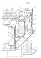
- packaging machine contains a feeder with one section or more Sections of endlessly rotating conveyor belts 2 guided over rollers 1, one of which the rollers 1 with one, not shown, operated intermittently or continuously Drive is coupled.
- Disc-shaped are located on the upper run of the conveyor belt 2 Objects 3, for example circular disk-shaped frozen dough pieces, frozen foods, baked goods and the like.
- the conveyor belt 2 conveys the objects 3 in the direction of one in the present Case circular discharge opening 6 in a horizontal upper housing deck 7 of Packaging machine, with not shown at the edges of the discharge opening 6 in Fig. 1, funnel-like baffles can be provided to achieve that of objects 3 thrown off the conveyor belt 2 fall safely through the discharge opening 6.
- axially somewhat projecting tabs 12 and 13 which with the stacking shaft 11 can be connected in one piece, serve to fasten the stacking shaft 11 in such a way between the housing decks 7 and 8 that to a subsequent purposes described in detail the upper end and the lower end of the Stacking shaft 11 from the side in the peripheral areas outside of the Tabs 12 and 13 occupied peripheral areas are freely accessible.
- the cross section of the interior of the stacking shaft 11 is the outline shape of the adapted to stacking objects 3 and is essentially in the present example circular.
- Lifting and lowering drives 14 and 15 and the lifting drives 14 and 15 with the Housing decks 7 and 8 connecting pivot bearings 16 and 17 or 18 and 19 contain.
- the lifting and lowering drives 14 and 15 are each guided by rollers Toothed belt 20 and 21 formed, the lower rollers by drive motors 22 or 23 can be changed separately according to certain control programs are controllable.
- the power supply and control lines to the Drive motors 22 and 23 are guided via flexible line connections.
- the respective lower pivot bearings 16 and 18 also a respective rotary drive for controllable pivoting of the drive devices 14 and 15 around vertical axes, respectively.
- Holding blocks 24 and 25 are attached, to which the cantilever arms 26 and 27 are anchored are.
- the cantilever arms are at their ends removed from the holding blocks 24 and 25, respectively 26 or 27 cranked and with these cranked ends firmly with circular disc-shaped Stacking pads 28 and 29 connected.
- the circular disk-shaped stacking pads 28 and 29 are designed so that they have ample play within the Stacking shaft 11 are movable downwards.
- the on the boom 27 through the slot 10 of the stacking shaft 11 The stacking pad 29 held is in the operating state shown in FIG. 1 already near the lower end of the stacking shaft 11 and carries a stack of objects 3 in a desired number or in a desired amount. While the Stacking pad 28 from the drive device or the lifting and lowering drive 14 moving relatively slowly downward while the stack is being built, the stacking pad 29 moves in with the stack already formed on it this operating phase relatively quickly by appropriate control of the engine 23 down a remaining path and the stacking pad 29, the boom 27 and the Drive device 15 are by corresponding control of the rotary drive on Locations of the pivot bearing 18 relatively quickly with respect to a clockwise supervision pivoted so that the stacking pad is then at the lower end of the stacking shaft 11 29 under the stacking shaft 11 and under the bottom of the finished finished Can be pivoted out, then the finished stack through the Transfer opening or passage opening 9 of the housing deck 8 in a bag or a bag falls on the stack picker.
- the boom 7 and the stacking pad hike at a relatively high speed up to an upper one Limit position from which the above-mentioned parts turn counterclockwise come to a position in which the stacking pad 29 above the upper End of the stacking shaft 11 is pivoted under the discharge opening 6.
- Fig. 1 shows no details of the stack removal device, which are together with a wrapping device or bagging device in a under the housing cover 8 located housing 30 is located. This is by means of a removal device 31 the wrapped or packed stacks are conveyed out.
- the drive devices 14 and 15 and their associated lifting and lowering drives and those provided in the area of their rotary bearings 16, 17, 18 and 19 Multi-turn actuators are connected via a control cable and power supply cables
- Drawing not shown central control unit connected to the detector signals of position indicators with regard to the respective state of the drive devices and detector signals relating to the speed of the feed device 2 and their occupation with objects to be stacked 3, as well as counter signals from the Counting devices determining the number of stacked objects are supplied.
- the control sequence of the individual parts of the packaging machine can be controlled by means of the central control unit be optimized so that due to the slow operation of the Drive devices, then rapid actuation and rapid return of the drive devices achieves a maximum working speed with trouble-free operation can be.
- the rotary drives within the rotary bearings 16, 17, 18 and 19 can also like the drive motors 22 and 23 for the toothed belts of the lifting and lowering drives 20 and 21 can be designed as stepper motors which act on pulses in such a manner be that both with respect to the pivoting movements of the drive devices 14th and 15, as well as the up and down movements of the stacking pads 28 and 29 smooth acceleration or deceleration transition phases between movement sections greatly different speed of movement can be provided. This causes a particularly gentle handling of the objects to be stacked 3 and trouble-free operation even at comparatively high clock speeds of up to 6000 items handled per hour.
- FIG. 1 While in the embodiment according to FIG. 1 a stacking shaft 11 has two stacking pads 28 and 29 and associated drive devices 14 and 15 assigned 2, the embodiment according to FIG. 2 schematically shows the architecture in supervision a corresponding packaging machine with three assigned to the stacking shaft 11 Stacking pads 28a, 28b and 28c, assigned to vertical axes of rotation 32a or 32b or 32c pivotable lifting and lowering drives 14a or 14b or 14c as well as fastening blocks of the lifting and lowering drives connecting the stacking pads Outriggers 26a and 26b and 26c. The arms are shown in FIG.
- FIG. 2 neither the lower housing cover corresponding to the housing cover 8 of the embodiment according to FIG. 1, details of the frame or machine frame are shown. Only the upper housing cover 7 is indicated by dash-dotted lines and has the embodiment shown approximately cruciform shape. This shape is of course, given here arbitrarily and can be modified as desired.
- Stack documents 28a executing work cycles which are phase-shifted by 120 °, 28b and 28c has the advantage of further increasing the working speed and an even gentler handling of the objects to be stacked, whereby in one in the vertical direction comparatively long stacking shaft 11 during the formation of a Stack of objects at the top of the stacking shaft at the same time a finished one Stack of items for transfer to the stack removal device at the bottom End of the stack shaft is underway.
- bracket with a vertical slot 10 provided stacking shaft 11 on the lower housing deck 8 and / or the upper Housing deck 7 must be made so that the upper stack end and lower end of the stacking shaft for the stacking pads, which in supervision the cross section of the Stacking chute are adapted approximately, remain freely accessible.
- This consideration is conditional some limitation on the arrangement of the axes about the vertical axes of rotation 32a, 32b and 32c pivotable drive devices, as this is based on the description of the Embodiment according to Fig. 2 was shown.
- the lifting and lowering drives for the Stacking pads should not be designed to be rotatable, but with horizontal displacement drives equip, as will be explained below with reference to FIG. 3.
- Fig. 3 shows a partial view of a single drive device with lifting and Lowering drive for a 28x stacking pad, which is connected to the drive element via a cantilever arm 26x 24x of a lifting and lowering drive 14x is connected.
- the hub and Lowering drive 14x contains, similar to the previously described embodiments shown, a toothed belt 20x guided over upper and lower rollers, but the Rolls, one of which in turn in a manner not shown in Fig. 3 a reversible motor is driven, not about rotating bearings after the Type of pivot bearings 16 to 19 of the embodiment of Fig. 1 with the housing decks 7 and 8 are connected, but on the housing decks via fixed bearing blocks are rigidly mounted, as in Fig. 3 at 35 with respect to the storage of the upper toothed belt roller is indicated on the upper housing deck 7.
- a horizontal displacement drive 36 which within the Drive member 24x of the lifting and lowering drive 14x is housed and in Fig. 3rd is indicated only schematically, it being expressly emphasized here that the training this horizontal displacement drive 36 in detail in many ways can and can also contain scissor drives by suitable drive means be operated.
- the cantilever arm is 26x in a certain section Rack formed, in which a pinion of the horizontal displacement drive 36th intervenes.
- the horizontal displacement drive 36 is over metallization 37th on the outer surface of the toothed belt 20x and via sliding contacts with control signals or supplied with energy.
- FIG. 3 In a packaging machine constructed according to the principles of FIG. 3 can, similar to the embodiment of FIG. 2, three stacking pads and associated lifting and lowering drives with respective horizontal displacement drives can be assigned to a stacking shaft, the connection in connection with FIG. 2 explained restrictions regarding the arrangement of the individual lifting and lowering drives only exist to a lesser extent in the embodiment according to FIG. 3. It is therefore possible when using the construction principles of FIG. 3 a single vertical very elongated stacking shaft also more than three stacking pads with associated Assign lifting and lowering drives, which means that the designer with regard to Adjustment of the height of the individual stacks to be formed, with regard to the working speed and even larger in handling the objects to be stacked There is scope.
Landscapes
- Engineering & Computer Science (AREA)
- Mechanical Engineering (AREA)
- Wrappers (AREA)
Applications Claiming Priority (2)
| Application Number | Priority Date | Filing Date | Title |
|---|---|---|---|
| DE10260014A DE10260014B4 (de) | 2002-12-19 | 2002-12-19 | Verpackungsmaschine für bruchempfindliche,flächige oder scheibenförmige Gegenstände |
| DE10260014 | 2002-12-19 |
Publications (3)
| Publication Number | Publication Date |
|---|---|
| EP1431186A2 true EP1431186A2 (fr) | 2004-06-23 |
| EP1431186A3 EP1431186A3 (fr) | 2004-08-04 |
| EP1431186B1 EP1431186B1 (fr) | 2006-03-01 |
Family
ID=32336514
Family Applications (1)
| Application Number | Title | Priority Date | Filing Date |
|---|---|---|---|
| EP03029319A Expired - Lifetime EP1431186B1 (fr) | 2002-12-19 | 2003-12-18 | Machine d'emballage pour des articles fragiles, plats ou en forme de disque |
Country Status (3)
| Country | Link |
|---|---|
| EP (1) | EP1431186B1 (fr) |
| AT (1) | ATE318758T1 (fr) |
| DE (2) | DE10260014B4 (fr) |
Cited By (7)
| Publication number | Priority date | Publication date | Assignee | Title |
|---|---|---|---|---|
| GB2436728A (en) * | 2006-03-31 | 2007-10-03 | United Biscuits Ltd | Packing planar articles |
| GB2475443A (en) * | 2006-03-31 | 2011-05-18 | United Biscuits Ltd | Forming and packing stacks of biscuits |
| IT201700047435A1 (it) * | 2017-05-03 | 2018-11-03 | Cavanna S P A Con Socio Unico | Apparecchio e procedimento per la formazione di gruppi di prodotti |
| CN110539932A (zh) * | 2019-08-15 | 2019-12-06 | 广东嘉仪仪器集团有限公司 | 一种取盖送盖系统 |
| CN111319812A (zh) * | 2020-03-13 | 2020-06-23 | 安徽盼盼食品有限公司 | 一种新型可调式无糖饼干生产用输送装置 |
| CN113320747A (zh) * | 2021-06-18 | 2021-08-31 | 哈工大机器人南昌智能制造研究院 | 一种糕点包装机的糕点叠放进料装置 |
| CN118494870A (zh) * | 2024-07-18 | 2024-08-16 | 江苏华夏瑞泰医疗器械有限公司 | 一种医用培养器皿生产用输送设备 |
Families Citing this family (1)
| Publication number | Priority date | Publication date | Assignee | Title |
|---|---|---|---|---|
| CN102951313B (zh) * | 2011-08-17 | 2014-09-17 | 赖新庭 | 饼干装载装置 |
Family Cites Families (9)
| Publication number | Priority date | Publication date | Assignee | Title |
|---|---|---|---|---|
| US3306475A (en) * | 1963-12-30 | 1967-02-28 | Mosaic Tile Company | Stacking apparatus |
| DE2219490C3 (de) * | 1972-04-18 | 1975-10-23 | F. Zimmermann & Co, 1000 Berlin | Vorrichtung zum Verpacken von senkrecht gestapelten Münzen, Wertzeichen od.dgl. Stapelteilen In einem aus einer Schrumpffolie bestehenden Beutel |
| DE3423948A1 (de) * | 1983-07-14 | 1985-01-24 | E.C.H. Will (Gmbh & Co), 2000 Hamburg | Vorrichtung zum fuellen eines einseitig offenen kartons mit einem papierstapel |
| IT1199414B (it) * | 1984-09-27 | 1988-12-30 | Ima Spa | Perfezionamenti alle macchine per la produzione automatica di sacchetti-filtro per prodotti da infusione |
| DE3943395C2 (de) * | 1989-12-30 | 1996-04-11 | Vse Verpackungs Und Sondermasc | Vorrichtung zum Verpacken von gefüllten Beuteln, insbesondere von in ihrer Dicke egalisierten gefüllten Schlauchbeuteln |
| DE4141830C2 (de) * | 1991-12-18 | 1996-02-29 | Philipp Waldinger | Stapel- und Verpackungsvorrichtung für Einzelstücke |
| EP0547485A1 (fr) * | 1991-12-18 | 1993-06-23 | Philipp Waldinger | Machine pour empiler et emballer des pièces unitaires comme des petites pièces de boulangerie |
| EP0561069B2 (fr) * | 1992-03-18 | 2000-04-05 | Matsushita Electric Industrial Co., Ltd. | Méthode pour l'empilement et le transfert des plaques pour accumulateurs au plomb et dispositif |
| DE69211674T3 (de) * | 1992-03-18 | 2000-11-16 | Matsushita Electric Industrial Co., Ltd. | Verfahren und Vorrichtung zum Stapeln und Transportieren von Bleiakkumulatorplatten. |
-
2002
- 2002-12-19 DE DE10260014A patent/DE10260014B4/de not_active Expired - Fee Related
-
2003
- 2003-12-18 DE DE50302520T patent/DE50302520D1/de not_active Expired - Fee Related
- 2003-12-18 AT AT03029319T patent/ATE318758T1/de not_active IP Right Cessation
- 2003-12-18 EP EP03029319A patent/EP1431186B1/fr not_active Expired - Lifetime
Cited By (11)
| Publication number | Priority date | Publication date | Assignee | Title |
|---|---|---|---|---|
| GB2436728A (en) * | 2006-03-31 | 2007-10-03 | United Biscuits Ltd | Packing planar articles |
| GB2436728B (en) * | 2006-03-31 | 2011-04-13 | United Biscuits Ltd | Improvements in or relating to the packing of articles |
| GB2475443A (en) * | 2006-03-31 | 2011-05-18 | United Biscuits Ltd | Forming and packing stacks of biscuits |
| GB2475443B (en) * | 2006-03-31 | 2011-07-06 | United Biscuits Ltd | Improvements in or relating to the packing of articles |
| IT201700047435A1 (it) * | 2017-05-03 | 2018-11-03 | Cavanna S P A Con Socio Unico | Apparecchio e procedimento per la formazione di gruppi di prodotti |
| EP3398863A1 (fr) * | 2017-05-03 | 2018-11-07 | Cavanna S.p.A. | Appareil et procédé de formation de groupes de produits |
| US10167097B2 (en) | 2017-05-03 | 2019-01-01 | Cavanna S.P.A. | Apparatus for forming groups of products |
| CN110539932A (zh) * | 2019-08-15 | 2019-12-06 | 广东嘉仪仪器集团有限公司 | 一种取盖送盖系统 |
| CN111319812A (zh) * | 2020-03-13 | 2020-06-23 | 安徽盼盼食品有限公司 | 一种新型可调式无糖饼干生产用输送装置 |
| CN113320747A (zh) * | 2021-06-18 | 2021-08-31 | 哈工大机器人南昌智能制造研究院 | 一种糕点包装机的糕点叠放进料装置 |
| CN118494870A (zh) * | 2024-07-18 | 2024-08-16 | 江苏华夏瑞泰医疗器械有限公司 | 一种医用培养器皿生产用输送设备 |
Also Published As
| Publication number | Publication date |
|---|---|
| EP1431186B1 (fr) | 2006-03-01 |
| DE10260014A1 (de) | 2004-07-15 |
| ATE318758T1 (de) | 2006-03-15 |
| DE50302520D1 (de) | 2006-04-27 |
| EP1431186A3 (fr) | 2004-08-04 |
| DE10260014B4 (de) | 2005-08-11 |
Similar Documents
| Publication | Publication Date | Title |
|---|---|---|
| DE69104843T2 (de) | Rotierende vorrichtung zum stapeln. | |
| DE102016105570B4 (de) | Umsetz-Vorrichtung für Produkte sowie Verfahren zu ihrem Betrieb | |
| DE1586073C3 (de) | Vorrichtung zum Beschicken des Speiseschachts einer Zigarettenmaschine | |
| CH631053A5 (de) | Vorrichtung zum herstellen von scheiben-portionen. | |
| EP0957055A2 (fr) | Dispositif d'empilage | |
| DE3700506C2 (fr) | ||
| DE1272211B (de) | Vorrichtung zum verpackungsgerechten Gruppieren von Gegenstaenden | |
| DE60308229T2 (de) | Vorrichtung zur lagerung und zuführung von produkten | |
| DE3734844A1 (de) | Bewegbare stapelvorrichtung fuer eine maschine zum aufschneiden laibfoermiger lebensmittel | |
| EP1431186B1 (fr) | Machine d'emballage pour des articles fragiles, plats ou en forme de disque | |
| DE69001751T2 (de) | Vorrichtung zum fuellen von behaeltern mit produkten gemaess einem bestimmten muster. | |
| DE1296578B (de) | Vorrichtung zum Stapeln von Walzstahlprofil-Staeben | |
| DE3221862A1 (de) | Vorrichtung zum zufuehren von behaeltern oder schachteln in einer auf zwei gegenueberliegenden seiten durchgehend geoeffneten form | |
| EP3502017A1 (fr) | Dispositif et procédé de manipulation des portions des denrées alimentaires à l'aide d'un agencement rotatif | |
| DE3015841A1 (de) | Stapelvorrichtung fuer flache artikel | |
| EP1445224B2 (fr) | Dispositif pour former des piles d'articles plats | |
| DE3339703A1 (de) | Vorrichtung zum verpacken von langgestreckten gegenstaenden, insbesondere zigaretten | |
| EP3670400A1 (fr) | Installation de mise en uvre et procédé de mise en uvre | |
| EP0526403B1 (fr) | Procédé et dispositif pour la fabrication de groupes de disques alimentaires | |
| DE69900048T2 (de) | Automatische Waagen für Nahrungsmittel | |
| DE3108195A1 (de) | Vorrichtung zum bilden von verpackungsfaehigen stapeln aus flachen werkstuecken | |
| DE102017104098A1 (de) | Kapselverpackungssystem | |
| DE102019112812A1 (de) | Portioniervorrichtung zum Bilden von Portionsstapeln, die jeweils mindestens eine mittels einer ein Messer aufweisenden Schneideinrichtung von einem Produktlaib abgetrennte Produktscheibe umfassen | |
| DE1527822B2 (de) | Vorrichtung zum Hersteller· von Walzdrahtbunden beliebigen Gewichtes aus horizontal herangeführten, einander überlappenden Drahtschlingen | |
| DE102007036726A1 (de) | Produkt-Fördereinrichtung |
Legal Events
| Date | Code | Title | Description |
|---|---|---|---|
| PUAI | Public reference made under article 153(3) epc to a published international application that has entered the european phase |
Free format text: ORIGINAL CODE: 0009012 |
|
| PUAL | Search report despatched |
Free format text: ORIGINAL CODE: 0009013 |
|
| AK | Designated contracting states |
Kind code of ref document: A2 Designated state(s): AT BE BG CH CY CZ DE DK EE ES FI FR GB GR HU IE IT LI LU MC NL PT RO SE SI SK TR |
|
| AX | Request for extension of the european patent |
Extension state: AL LT LV MK |
|
| AK | Designated contracting states |
Kind code of ref document: A3 Designated state(s): AT BE BG CH CY CZ DE DK EE ES FI FR GB GR HU IE IT LI LU MC NL PT RO SE SI SK TR |
|
| AX | Request for extension of the european patent |
Extension state: AL LT LV MK |
|
| 17P | Request for examination filed |
Effective date: 20050113 |
|
| AKX | Designation fees paid |
Designated state(s): AT BE BG CH CY CZ DE DK EE ES FI FR GB GR HU IE IT LI LU MC NL PT RO SE SI SK TR |
|
| GRAP | Despatch of communication of intention to grant a patent |
Free format text: ORIGINAL CODE: EPIDOSNIGR1 |
|
| GRAS | Grant fee paid |
Free format text: ORIGINAL CODE: EPIDOSNIGR3 |
|
| GRAA | (expected) grant |
Free format text: ORIGINAL CODE: 0009210 |
|
| AK | Designated contracting states |
Kind code of ref document: B1 Designated state(s): AT BE BG CH CY CZ DE DK EE ES FI FR GB GR HU IE IT LI LU MC NL PT RO SE SI SK TR |
|
| PG25 | Lapsed in a contracting state [announced via postgrant information from national office to epo] |
Ref country code: IT Free format text: LAPSE BECAUSE OF FAILURE TO SUBMIT A TRANSLATION OF THE DESCRIPTION OR TO PAY THE FEE WITHIN THE PRESCRIBED TIME-LIMIT;WARNING: LAPSES OF ITALIAN PATENTS WITH EFFECTIVE DATE BEFORE 2007 MAY HAVE OCCURRED AT ANY TIME BEFORE 2007. THE CORRECT EFFECTIVE DATE MAY BE DIFFERENT FROM THE ONE RECORDED. Effective date: 20060301 Ref country code: FI Free format text: LAPSE BECAUSE OF FAILURE TO SUBMIT A TRANSLATION OF THE DESCRIPTION OR TO PAY THE FEE WITHIN THE PRESCRIBED TIME-LIMIT Effective date: 20060301 Ref country code: RO Free format text: LAPSE BECAUSE OF FAILURE TO SUBMIT A TRANSLATION OF THE DESCRIPTION OR TO PAY THE FEE WITHIN THE PRESCRIBED TIME-LIMIT Effective date: 20060301 Ref country code: SI Free format text: LAPSE BECAUSE OF FAILURE TO SUBMIT A TRANSLATION OF THE DESCRIPTION OR TO PAY THE FEE WITHIN THE PRESCRIBED TIME-LIMIT Effective date: 20060301 Ref country code: IE Free format text: LAPSE BECAUSE OF FAILURE TO SUBMIT A TRANSLATION OF THE DESCRIPTION OR TO PAY THE FEE WITHIN THE PRESCRIBED TIME-LIMIT Effective date: 20060301 Ref country code: SK Free format text: LAPSE BECAUSE OF FAILURE TO SUBMIT A TRANSLATION OF THE DESCRIPTION OR TO PAY THE FEE WITHIN THE PRESCRIBED TIME-LIMIT Effective date: 20060301 Ref country code: GB Free format text: LAPSE BECAUSE OF FAILURE TO SUBMIT A TRANSLATION OF THE DESCRIPTION OR TO PAY THE FEE WITHIN THE PRESCRIBED TIME-LIMIT Effective date: 20060301 Ref country code: NL Free format text: LAPSE BECAUSE OF FAILURE TO SUBMIT A TRANSLATION OF THE DESCRIPTION OR TO PAY THE FEE WITHIN THE PRESCRIBED TIME-LIMIT Effective date: 20060301 |
|
| REG | Reference to a national code |
Ref country code: GB Ref legal event code: FG4D Free format text: NOT ENGLISH |
|
| REG | Reference to a national code |
Ref country code: CH Ref legal event code: EP |
|
| REG | Reference to a national code |
Ref country code: IE Ref legal event code: FG4D Free format text: LANGUAGE OF EP DOCUMENT: GERMAN |
|
| REF | Corresponds to: |
Ref document number: 50302520 Country of ref document: DE Date of ref document: 20060427 Kind code of ref document: P |
|
| PG25 | Lapsed in a contracting state [announced via postgrant information from national office to epo] |
Ref country code: SE Free format text: LAPSE BECAUSE OF FAILURE TO SUBMIT A TRANSLATION OF THE DESCRIPTION OR TO PAY THE FEE WITHIN THE PRESCRIBED TIME-LIMIT Effective date: 20060601 Ref country code: DK Free format text: LAPSE BECAUSE OF FAILURE TO SUBMIT A TRANSLATION OF THE DESCRIPTION OR TO PAY THE FEE WITHIN THE PRESCRIBED TIME-LIMIT Effective date: 20060601 Ref country code: BG Free format text: LAPSE BECAUSE OF FAILURE TO SUBMIT A TRANSLATION OF THE DESCRIPTION OR TO PAY THE FEE WITHIN THE PRESCRIBED TIME-LIMIT Effective date: 20060601 |
|
| PG25 | Lapsed in a contracting state [announced via postgrant information from national office to epo] |
Ref country code: ES Free format text: LAPSE BECAUSE OF FAILURE TO SUBMIT A TRANSLATION OF THE DESCRIPTION OR TO PAY THE FEE WITHIN THE PRESCRIBED TIME-LIMIT Effective date: 20060612 |
|
| PG25 | Lapsed in a contracting state [announced via postgrant information from national office to epo] |
Ref country code: PT Free format text: LAPSE BECAUSE OF FAILURE TO SUBMIT A TRANSLATION OF THE DESCRIPTION OR TO PAY THE FEE WITHIN THE PRESCRIBED TIME-LIMIT Effective date: 20060801 |
|
| NLV1 | Nl: lapsed or annulled due to failure to fulfill the requirements of art. 29p and 29m of the patents act | ||
| GBV | Gb: ep patent (uk) treated as always having been void in accordance with gb section 77(7)/1977 [no translation filed] |
Effective date: 20060301 |
|
| REG | Reference to a national code |
Ref country code: IE Ref legal event code: FD4D |
|
| PG25 | Lapsed in a contracting state [announced via postgrant information from national office to epo] |
Ref country code: BE Free format text: LAPSE BECAUSE OF NON-PAYMENT OF DUE FEES Effective date: 20061231 Ref country code: MC Free format text: LAPSE BECAUSE OF NON-PAYMENT OF DUE FEES Effective date: 20061231 |
|
| PLBE | No opposition filed within time limit |
Free format text: ORIGINAL CODE: 0009261 |
|
| STAA | Information on the status of an ep patent application or granted ep patent |
Free format text: STATUS: NO OPPOSITION FILED WITHIN TIME LIMIT |
|
| 26N | No opposition filed |
Effective date: 20061204 |
|
| EN | Fr: translation not filed | ||
| BERE | Be: lapsed |
Owner name: S+R ELEKTROANLAGEN G.M.B.H. Effective date: 20061231 |
|
| PG25 | Lapsed in a contracting state [announced via postgrant information from national office to epo] |
Ref country code: AT Free format text: LAPSE BECAUSE OF NON-PAYMENT OF DUE FEES Effective date: 20061218 |
|
| PG25 | Lapsed in a contracting state [announced via postgrant information from national office to epo] |
Ref country code: FR Free format text: LAPSE BECAUSE OF FAILURE TO SUBMIT A TRANSLATION OF THE DESCRIPTION OR TO PAY THE FEE WITHIN THE PRESCRIBED TIME-LIMIT Effective date: 20070309 Ref country code: CZ Free format text: LAPSE BECAUSE OF FAILURE TO SUBMIT A TRANSLATION OF THE DESCRIPTION OR TO PAY THE FEE WITHIN THE PRESCRIBED TIME-LIMIT Effective date: 20060301 Ref country code: GR Free format text: LAPSE BECAUSE OF FAILURE TO SUBMIT A TRANSLATION OF THE DESCRIPTION OR TO PAY THE FEE WITHIN THE PRESCRIBED TIME-LIMIT Effective date: 20060602 |
|
| PG25 | Lapsed in a contracting state [announced via postgrant information from national office to epo] |
Ref country code: EE Free format text: LAPSE BECAUSE OF FAILURE TO SUBMIT A TRANSLATION OF THE DESCRIPTION OR TO PAY THE FEE WITHIN THE PRESCRIBED TIME-LIMIT Effective date: 20060301 |
|
| PG25 | Lapsed in a contracting state [announced via postgrant information from national office to epo] |
Ref country code: TR Free format text: LAPSE BECAUSE OF FAILURE TO SUBMIT A TRANSLATION OF THE DESCRIPTION OR TO PAY THE FEE WITHIN THE PRESCRIBED TIME-LIMIT Effective date: 20060301 Ref country code: LU Free format text: LAPSE BECAUSE OF NON-PAYMENT OF DUE FEES Effective date: 20061218 Ref country code: HU Free format text: LAPSE BECAUSE OF FAILURE TO SUBMIT A TRANSLATION OF THE DESCRIPTION OR TO PAY THE FEE WITHIN THE PRESCRIBED TIME-LIMIT Effective date: 20060902 |
|
| REG | Reference to a national code |
Ref country code: CH Ref legal event code: PL |
|
| PG25 | Lapsed in a contracting state [announced via postgrant information from national office to epo] |
Ref country code: CH Free format text: LAPSE BECAUSE OF NON-PAYMENT OF DUE FEES Effective date: 20071231 Ref country code: LI Free format text: LAPSE BECAUSE OF NON-PAYMENT OF DUE FEES Effective date: 20071231 |
|
| PG25 | Lapsed in a contracting state [announced via postgrant information from national office to epo] |
Ref country code: CY Free format text: LAPSE BECAUSE OF FAILURE TO SUBMIT A TRANSLATION OF THE DESCRIPTION OR TO PAY THE FEE WITHIN THE PRESCRIBED TIME-LIMIT Effective date: 20060301 Ref country code: FR Free format text: LAPSE BECAUSE OF FAILURE TO SUBMIT A TRANSLATION OF THE DESCRIPTION OR TO PAY THE FEE WITHIN THE PRESCRIBED TIME-LIMIT Effective date: 20060301 |
|
| PGFP | Annual fee paid to national office [announced via postgrant information from national office to epo] |
Ref country code: DE Payment date: 20081208 Year of fee payment: 6 |
|
| PG25 | Lapsed in a contracting state [announced via postgrant information from national office to epo] |
Ref country code: DE Free format text: LAPSE BECAUSE OF NON-PAYMENT OF DUE FEES Effective date: 20100701 |