EP1432001B1 - Elektrisches Gerät, beispielsweise modulares elektrisches Gerät mit einem zweiteiligen Gehäuse - Google Patents
Elektrisches Gerät, beispielsweise modulares elektrisches Gerät mit einem zweiteiligen Gehäuse Download PDFInfo
- Publication number
- EP1432001B1 EP1432001B1 EP02360377A EP02360377A EP1432001B1 EP 1432001 B1 EP1432001 B1 EP 1432001B1 EP 02360377 A EP02360377 A EP 02360377A EP 02360377 A EP02360377 A EP 02360377A EP 1432001 B1 EP1432001 B1 EP 1432001B1
- Authority
- EP
- European Patent Office
- Prior art keywords
- electrical device
- block
- electrical
- truncated
- connection
- Prior art date
- Legal status (The legal status is an assumption and is not a legal conclusion. Google has not performed a legal analysis and makes no representation as to the accuracy of the status listed.)
- Expired - Lifetime
Links
Images
Classifications
-
- H—ELECTRICITY
- H01—ELECTRIC ELEMENTS
- H01H—ELECTRIC SWITCHES; RELAYS; SELECTORS; EMERGENCY PROTECTIVE DEVICES
- H01H71/00—Details of the protective switches or relays covered by groups H01H73/00 - H01H83/00
- H01H71/08—Terminals; Connections
- H01H71/082—Connections between juxtaposed circuit breakers
-
- H—ELECTRICITY
- H01—ELECTRIC ELEMENTS
- H01H—ELECTRIC SWITCHES; RELAYS; SELECTORS; EMERGENCY PROTECTIVE DEVICES
- H01H11/00—Apparatus or processes specially adapted for the manufacture of electric switches
- H01H11/0006—Apparatus or processes specially adapted for the manufacture of electric switches for converting electric switches
- H01H11/0031—Apparatus or processes specially adapted for the manufacture of electric switches for converting electric switches for allowing different types or orientation of connections to contacts
- H01H2011/0037—Apparatus or processes specially adapted for the manufacture of electric switches for converting electric switches for allowing different types or orientation of connections to contacts with removable or replaceable terminal blocks
Definitions
- the present invention relates to electrical devices of the circuit breaker, block or differential switch type said modular comprising an insulating housing, and intended to be mounted on a rail or other mounting bracket, contiguous to other electrical appliances of the same type to form a electrical distribution circuit.
- the invention does not relate exclusively to devices classified as modular, which in principle obey a fairly precise sizing, but it finds with them a privileged and majority field of application.
- these devices comprise a housing which incorporates functional means enabling them to fill the electrical objective assigned to them, said housing further having means for fixing and holding on the rail or the support.
- the housings To be integrated in the distribution circuit, generally located in a distribution panel centralizing the modular equipment, the housings finally include input and output connection means opening in their faces perpendicular to both the rail and the plane of connection, for the connection of at least one individual conductor or part of a bridging bar which can also be connected to adjacent contiguous appliances.
- the modular electrical devices on each rail are used both in single and multiphase electrical circuits, allowing in each case multiple possibilities of configurations and / or solutions connection.
- the distribution of the neutral and / or phases, in particular, is often carried out using rigid bridging bars having regularly spaced connecting tongues, intended to be introduced into the connectors of the various electrical devices arranged on the rail.
- a bridging bar therefore makes it impossible to use appliances whose connection devices are spaced apart in a different pitch, that is to say electrical appliances integrated in a housing whose width represents a multiple or a sub-multiple of that of a module.
- EP-A-1 014 414 discloses an electrical apparatus according to the preamble of claim 1.
- the present invention proposes a solution which allows a decorrelation between the connection pitch of the external distribution on the one hand and the pitch of the installed electrical appliances on the other hand, and which substantially reduces the number and the bulk of the connection elements to the current modular housings.
- the invention also makes it possible to maintain compatibility with the distribution solutions that are already in place, and in particular the supply of modular devices by rigid bridging bars and individual conductors.
- the system of the invention leads to a reduction in production costs by pooling certain functions, when it applies to several appliances contiguous.
- Said invention consists in fact of a modular circuit breaker, block or differential switch electrical appliance according to claim 1.
- the volume initially devolved to the housing of conventional electrical appliances is divided into two parts, one of which includes the functional core that provides the electrical function or functions, and the other is actually a distribution accessory that ensures the electrical connection or interfacing between at least one external conductor and said functional core.
- the removable block is shared between several boxes, the latter being all truncated to be able to integrate the block by plugging. This results in a significant reduction in the number of external power supply conductors for the phases and / or the neutral, the power being only once for the removable block, instead of an individual connection for each device as is the case in existing configurations.
- the input connection means are spaced by a pitch p 1 corresponding to the modular pitch of the connecting tabs bridging bars and the length of said removable block is an integer multiple of this pitch p 1 .
- Respect for the spacing of the connection openings and the bridging level makes it possible, in particular, to use conventional bridging bars, when the device of the invention is integrated, on a mounting rail, between electrical appliances equipped with conventional housings. .
- Each removable block therefore comprises a single set of input connection means for each phase and / or the neutral, the existence of a set of connection means for each phase and for the neutral depending on the electrical configuration presented by the truncated boxes to which the block is connected.
- This structure allows a great flexibility of operation, whether in the initial design of the distribution board, for maintenance or for the replacement of products if necessary. This flexibility is reflected not only in the initial work of designing the table, but also in the increased ease and speed of on-site interventions in the event of a problem, for example the disassembly for testing or the change of a product being almost instantaneous. .
- an electrical apparatus that is to say having a removable block supporting the input connection functions is arranged placed between conventional modular devices, themselves connected by a comb bridging, and that the removable block has a length that substantially exceeds the area in which the connection means are arranged, it is necessary to provide the management of the unused connection tabs of the bridging bar.
- the block comprises means for housing said tabs, in its face into which the inlet connection means open, at least in areas without these means.
- the new devices provided with the removable block according to the invention, can therefore be placed on one or both of their sides to conventional modular devices, without any restriction.
- said housing means consist of at least one rectilinear groove extending parallel to the rail or other support of fixation.
- the connection tabs of the bridging blade or blades then fit into the slot (s) located at their bridging level in the removable block, without they have an electrical connection to the inside the block.
- said groove may be replaced by cells.
- the downstream electrical connection means are spaced apart by a regular step p 2 which, as already mentioned, is not necessarily equal to the aforementioned step p 1 . It is therefore at this level that decorrelation takes place between the external pitch, as input, and the internal pitch, downstream.
- the pitch p 2 separating the fast downstream connection means is a multiple or a sub-multiple of the pitch p 1 . This is particularly the case when the removable block of the invention is to be used to interface truncated double or triple modules.
- the removable block comprises downstream means for fast electrical connection truncated boxes, that is to say, pluggable and removable preferably without tools.
- Said fast connection means consist for example of conductive tabs cooperating with spring blades also conductive so as to establish an electrical connection between the removable block and the truncated housing (s).
- This structure is easy to implement and provides a secure electrical connection.
- the tongues, and if necessary that the leaf spring are further subject to a type IP2X protection.
- each tongue is surrounded by a conductive wall of form intended to fit into a correspondingly shaped orifice located in the truncated housing at the outlet of the spring blade with which she cooperates.
- the tabs are attached to the removable block and the spring blade connectors are integrated in the truncated housing.
- the removable block and truncated housings to which it is attached can be pre-assembled in a compact block, and then mounted on the rail or the support.
- the extraction of a single truncated case, and its replacement can easily be implemented by plugging a new truncated case on the or the tabs protruding from the block attached to the other truncated housings mounted on the rail or the support.
- the removable block allows a second level of design and realization of a part of the distribution circuit, which is totally independent of the input connections. arranged out of the volumes of the traditional complete boxes.
- the choice of the removable block orients the configuration of the circuit downstream of this block (width) to a certain extent, but the user retains the choice, particularly as a function of the spacing of the downstream connection means, of a certain number of circuits. possible electrical power, which depends on the selected devices.
- removable blocks serve in particular connection accessories integrated to the complete volumes of the housings, and they therefore release, between two adjacent rows, a significant space because they can significantly limit the number of external connection conductors.
- the space between two rows of adjacent devices being very limited, and not conducive to handling involved in the development of circuits, or during replacement during maintenance operations, is thus used optimally with the structure of the invention.
- the removable block may comprise fastening means to the rail or the fixing support which are also shared.
- At least one rail fastening latch can for example be mounted so as to slide on said part.
- the removable block cooperates with several boxes of different electrical appliances, and depending on its length, it can provide only one or two latches. In any case, their number does not necessarily correspond to the number of truncated housings of modular devices fixed downstream of the removable block, and in most cases remains less than this number.
- the removable block may include a differential switch controlling the electrical devices connected to the block, and dispensing to provide a specific housing for this function.
- the removable blocks may be provided with a surge arrester, a voltage indicator, a phase balance indicator, etc.
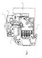
- the truncated housing (2) integrates the essential electrical functions of the electrical apparatus (1).
- said truncated housing (2) and the removable block (3) constitute an electrical appliance whose external dimensions recreate the volume of traditional modular electrical appliances.
- the removable block (3) develops from the front (4) of the product to its sole (5), and over the entire width of the device, and it therefore includes the face in which the means open input connection.
- the interlocking of the removable block (3) on the truncated casing (2) is in particular made possible by the complementarity of the shapes facing these two parts.
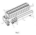
- the figure 2 shows an example of a series of functional cores, represented by their truncated housing (2), intended to cooperate with a single removable block (3), therefore of a length adapted to the sum of the widths of the modules (2).
- the group formed by the truncated housings (2) connected to the removable block (3) is then intended to be placed on a support rail to a conventional modular device (6).
- the configuration shown is intended to be used in a three-phase circuit, and the means of input connection (8) are therefore three in number.
- These connection means are in this case traditional clamping screw cages, said screws being accessible via orifices (9) disposed in the upper part of the block (3) in the extension of the facade (4).
- the downstream connection means for electrically connecting said block (3) to the truncated housings (2) are not visible in this figure. They are designed to fit into the orifices (11) represented on the small lateral sides of said truncated housings (2) facing the block (3).
- the removable block (3) intended to cooperate with 12 boxes of width corresponding to a module, has only two latches (7) for attachment to the mounting rail.
- the fixing notches (appearing in particular in figure 1 ) located in the truncated housing at the sole (5) are 12, one per product, and cooperate with two latches (7). This obviously leads to a financial gain, saving parts and simplification of assembly, which is significant in reference to the amount of devices produced.
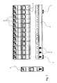
- FIG. 3 having a configuration identical to that of the figure 2 , makes more apparent the type of downstream electrical connection used to connect the removable block (3) truncated housings (2). It is in this case circular studs (10) intended to be inserted into the above-mentioned orifices (11), which will be described in more detail with reference to FIG. figure 5 . These circular studs (10), however, have only a mechanical connection and guiding function, the electrical connection being provided by a tongue disposed inside said pads (10).
- the object of the figure 4 is simply to show that once assembled, the removable block (3) and truncated housings (2) have a transverse profile which is equivalent to that of the conventional modular device (6).
- Such conventional devices can therefore be joined on either side of the group formed by said block (3) attached to the truncated housing (2).
- the new configuration does not encroach on spaces traditionally devolved to external conductors.
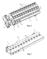
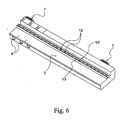
- the figure 5 shows the removable block (3) used in the Figures 2 to 4 but in an opposite direction.
- the pads (10) surround well electrical connection tabs (12), which are provided to plug into spring blades disposed in the truncated housings (2), and opening at the openings (11).
- the figure 6 constitutes a possible variant of the downstream electrical connection system of the figure 5 , according to which the blades (12) are this time inserted between two parallel walls (13, 13 '). These walls (13, 13 '), as well as the cylindrical studs (10), are intended to protect the user against accidental contact on the tabs, according to current safety standards.
- the pitch of the downstream connection means is equal to the pitch of the input connection means (8).
- the main purpose of the removable block (3) being to perform a decorrelation between the upstream step of the input connection means and the downstream step. This objective must be fulfilled without breaking the compatibility with the existing electrical modular devices, whatever the size of the removable block (3).
Landscapes
- Coupling Device And Connection With Printed Circuit (AREA)
- Connections Arranged To Contact A Plurality Of Conductors (AREA)
- Details Of Connecting Devices For Male And Female Coupling (AREA)
Claims (19)
- Elektrisches Gerät des Typs modularer Schaltautomat, differentieller Block oder differentieller Unterbrecher, mit einem isolierenden Gehäuse (1), das dazu vorgesehen ist, an einer Schiene oder an irgendeinem anderen Befestigungsträger montiert zu werden, und an andere elektrische Geräte (6) angefügt ist, um eine elektrische Verteilerschaltung zu bilden, und das zu diesem Zweck versehen ist mit Eingangsanschlussmitteln (8) und Ausgangsanschlussmitteln, die in seine Seiten münden, die einen zu der Schiene oder dem Träger und zu der Anfügungsebene senkrechten Verlauf haben, um mit wenigstens einem einzelnen Leiter oder mit einem Leiter, der einen Teil eines Überbrückungsstabs bildet, der mit jedem angefügten benachbarten Gerät (6) verbunden werden kann, verbunden zu werden, wobei das Gehäuse (1) in zwei mechanisch und elektrisch verbindbare und trennbare Teile unterteilt ist, die ein abgeschnittenes Gehäuse (2) und einen abnehmbaren Block (3) bilden, der die Eingangsverbindungsmittel (8), die über einen einzelnen Leiter die Verbindung mit der Verteilungsschaltung des Geräts ermöglichen, sowie ausgangsseitige Mittel (12) für die elektrische Verbindung mit dem abgeschnittenen Gehäuse (2) enthält, dadurch gekennzeichnet, dass der abnehmbare Block (3) die Verbindung durch den Überbrückungsstab ermöglicht und von wenigstens zwei aneinander gefügten abgeschnittenen Gehäusen (2) gemeinsam genutzt werden kann, und dass dann, wenn mehr als eine zu verbindende Phase vorhanden ist, die Eingangsverbindungsmittel (8) um eine Schrittweite p1 beabstandet sind, die jener der Anschlussstecker des Verbindungsstabs entspricht, wobei die Länge des abnehmbaren Blocks (3) ein ganzzahliges Vielfaches dieser Schrittweite p1 ist.
- Elektrisches Gerät nach dem vorhergehenden Anspruch, dadurch gekennzeichnet, dass der abnehmbare Block (3) eine einzige Gesamtheit von Eingangsverbindungsmitteln (8) pro Phase und/oder für den Nullleiter enthält, wobei das Vorhandensein einer Gesamtheit von Verbindungsmitteln (8) für jede Phase und für den Nullleiter von der elektrischen Konfiguration abhängt, die die abgeschnittenen Gehäuse, mit denen der Block (3) verbunden wird, aufweisen.
- Elektrisches Gerät nach einem der vorhergehenden Ansprüche, dadurch gekennzeichnet, dass der Block (3) Mittel für die Aufnahme der Anschlussstecker der Überbrückungsstäbe in seiner Fläche, in die die Eingangsverbindungsmittel (8) münden, zumindest in jenen Zonen, in denen diese Mittel nicht vorhanden sind, enthält.
- Elektrisches Gerät nach dem vorhergehenden Anspruch, dadurch gekennzeichnet, dass die Aufnahmemittel aus wenigstens einer geradlinigen Nut bestehen, die sich parallel zu der Schiene oder dem Befestigungsträger erstreckt.
- Elektrisches Gerät nach Anspruch 3, dadurch gekennzeichnet, dass die Aufnahmemittel aus Steckbuchsen bestehen.
- Elektrisches Gerät nach einem der vorhergehenden Ansprüche, dadurch gekennzeichnet, dass die ausgangsseitigen elektrischen Verbindungsmittel (12) um eine regelmäßige Schrittweite p2 beabstandet sind.
- Elektrisches Gerät nach dem vorhergehenden Anspruch, dadurch gekennzeichnet, dass die Schrittweite p2, die die Verbindungsmittel (12) trennt, ein Vielfaches oder ein Untervielfaches der Schrittweite p1 ist.
- Elektrisches Gerät nach einem der Ansprüche 5 und 6, dadurch gekennzeichnet, dass der abnehmbare Block (3) auf der Ausgangsseite elektrische Schnellverbindungsmittel mit jedem abgeschnittenen Gehäuse (2) des elektrischen Geräts (1) aufweist, die vorzugsweise ohne Werkzeug einsteckbar und herausziehbar sind.
- Elektrisches Gerät nach dem vorhergehenden Anspruch, dadurch gekennzeichnet, dass die Schnellverbindungsmittel aus leitenden Steckern (12) bestehen, die mit ebenfalls leitenden Federplättchen zusammenwirken, derart, dass zwischen dem abnehmbaren Block (3) und dem oder den abgeschnittenen Gehäusen (2) eine elektrische Verbindung hergestellt wird.
- Elektrisches Gerät nach dem vorhergehenden Anspruch, dadurch gekennzeichnet, dass die Stecker (12) und die Federplättchen den Gegenstand eines Schutzes des Typs IP2X bilden.
- Elektrisches Gerät nach dem vorhergehenden Anspruch, dadurch gekennzeichnet, dass jeder Stecker (12) von einer isolierenden Wand (10; 13, 13') umgeben ist, die eine Form hat, die geeignet ist, in eine Öffnung (11) mit entsprechender Form eingesteckt zu werden, die sich an der Mündung des Federplättchens befindet, mit der der Stecker (12) zusammenwirkt.
- Elektrisches Gerät nach einem der Ansprüche 8 bis 10, dadurch gekennzeichnet, dass die Stecker (12) an den abnehmbaren Block (3) angefügt sind und dass die Verbinder mit Federplättchen in die abgeschnittenen Gehäuse (2) integriert sind.
- Elektrisches Gerät nach einem der vorhergehenden Ansprüche, dadurch gekennzeichnet, dass der abnehmbare Block (3) Mittel für die Befestigung an der Schiene oder an dem Befestigungsträger enthält.
- Elektrisches Gerät nach dem vorhergehenden Anspruch, dadurch gekennzeichnet, dass die Mittel für die Befestigung an der Schiene aus wenigstens einer Falle (7) bestehen, die längs einer Fläche des abnehmbaren Blocks (3) gleitet, die die Fußplatte (5) des oder der abgeschnittenen Gehäuse (2), mit denen der Block (3) verbunden ist, verlängert.
- Elektrisches Gerät nach einem der vorhergehenden Ansprüche, dadurch gekennzeichnet, dass der abnehmbare Block (3) einen differentiellen Unterbrecher enthält.
- Elektrisches Gerät nach einem der vorhergehenden Ansprüche, dadurch gekennzeichnet, dass der abnehmbare Block (3) einen Überspannungsableiter enthält.
- Elektrisches Gerät nach einem der vorhergehenden Ansprüche, dadurch gekennzeichnet, dass der abnehmbare Block (3) eine Spannungsanzeigeeinrichtung enthält.
- Elektrisches Gerät nach einem der vorhergehenden Ansprüche, dadurch gekennzeichnet, dass der abnehmbare Block (3) eine Phasengleichheits-Anzeigeeinrichtung enthält.
- Elektrisches Gerät nach einem der vorhergehenden Ansprüche, dadurch gekennzeichnet, dass jeder Block (3) Mittel für die mechanische Montage und die elektrische Verbindung mit wenigstens einem weiteren Block (3) enthält, um sie in einer Richtung parallel zu jener der Schiene oder des Montageträgers zusammenzufügen.
Priority Applications (3)
| Application Number | Priority Date | Filing Date | Title |
|---|---|---|---|
| DE60227086T DE60227086D1 (de) | 2002-12-20 | 2002-12-20 | Elektrisches Gerät, beispielsweise modulares elektrisches Gerät mit einem zweiteiligen Gehäuse |
| EP02360377A EP1432001B1 (de) | 2002-12-20 | 2002-12-20 | Elektrisches Gerät, beispielsweise modulares elektrisches Gerät mit einem zweiteiligen Gehäuse |
| AT02360377T ATE398334T1 (de) | 2002-12-20 | 2002-12-20 | Elektrisches gerät, beispielsweise modulares elektrisches gerät mit einem zweiteiligen gehäuse |
Applications Claiming Priority (1)
| Application Number | Priority Date | Filing Date | Title |
|---|---|---|---|
| EP02360377A EP1432001B1 (de) | 2002-12-20 | 2002-12-20 | Elektrisches Gerät, beispielsweise modulares elektrisches Gerät mit einem zweiteiligen Gehäuse |
Publications (2)
| Publication Number | Publication Date |
|---|---|
| EP1432001A1 EP1432001A1 (de) | 2004-06-23 |
| EP1432001B1 true EP1432001B1 (de) | 2008-06-11 |
Family
ID=32338220
Family Applications (1)
| Application Number | Title | Priority Date | Filing Date |
|---|---|---|---|
| EP02360377A Expired - Lifetime EP1432001B1 (de) | 2002-12-20 | 2002-12-20 | Elektrisches Gerät, beispielsweise modulares elektrisches Gerät mit einem zweiteiligen Gehäuse |
Country Status (3)
| Country | Link |
|---|---|
| EP (1) | EP1432001B1 (de) |
| AT (1) | ATE398334T1 (de) |
| DE (1) | DE60227086D1 (de) |
Families Citing this family (3)
| Publication number | Priority date | Publication date | Assignee | Title |
|---|---|---|---|---|
| EP1962320B1 (de) * | 2007-02-22 | 2011-11-16 | Hager-Electro SAS | Elektrisches Gerät in Blockmodulbauweise |
| FR3039698B1 (fr) | 2015-07-31 | 2019-08-30 | Hager-Electro Sas | Ensemble de boitiers d'appareils electriques mecaniquement et electriquement relies entre eux |
| FR3094581A1 (fr) * | 2019-03-26 | 2020-10-02 | Schneider Electric Industries Sas | Dispositif d’alimentation et de raccordement electrique d’un ensemble d’appareils modulaires montes sur un support de montage. |
Family Cites Families (7)
| Publication number | Priority date | Publication date | Assignee | Title |
|---|---|---|---|---|
| DE1280382B (de) * | 1966-09-07 | 1968-10-17 | Stotz Kontakt Gmbh | Vorrichtung zur Fehlerstromueberwachung eines verzweigten Ein- oder Mehrphasennetzes |
| FR2722332B1 (fr) * | 1994-07-06 | 1996-09-13 | Schneider Electric Sa | Bloc auxiliaire notamment de signalisation de l'etat de disjoncteurs |
| ES2274570T3 (es) * | 1998-05-29 | 2007-05-16 | Hager Electro S.A. | Dispositivo de acoplamiento de dos elementos electricos modulares juntos. |
| FR2787917B1 (fr) * | 1998-12-23 | 2001-03-16 | Schneider Electric Ind Sa | Appareil electrique tel un disjoncteur ou un interrupteur modulaire |
| EP1085550A3 (de) * | 1999-09-13 | 2002-08-28 | ABB PATENT GmbH | Installationsschalter |
| FR2809876B1 (fr) * | 2000-05-31 | 2002-07-26 | Schneider Electric Ind Sa | Appareil electrique modulaire a embrochage sur un repartisseur isole |
| DE10120677B4 (de) * | 2001-04-27 | 2010-11-04 | Siemens Ag | Modulares Reiheneinbaugerät |
-
2002
- 2002-12-20 DE DE60227086T patent/DE60227086D1/de not_active Expired - Lifetime
- 2002-12-20 AT AT02360377T patent/ATE398334T1/de not_active IP Right Cessation
- 2002-12-20 EP EP02360377A patent/EP1432001B1/de not_active Expired - Lifetime
Also Published As
| Publication number | Publication date |
|---|---|
| DE60227086D1 (de) | 2008-07-24 |
| EP1432001A1 (de) | 2004-06-23 |
| ATE398334T1 (de) | 2008-07-15 |
Similar Documents
| Publication | Publication Date | Title |
|---|---|---|
| EP1376638B1 (de) | Elektromagnetischer Schutz und Steuereinheit | |
| FR2780206A1 (fr) | Ensemble formant bloc de distribution d'energie, et barre omnibus de transmission d'energie | |
| EP0726614B1 (de) | Zusammensetzbare elektrische Schnittstellenvorrichtung | |
| EP0734099B1 (de) | Modulare elektrische Reihenklemmenanordnung | |
| EP1432001B1 (de) | Elektrisches Gerät, beispielsweise modulares elektrisches Gerät mit einem zweiteiligen Gehäuse | |
| EP0524115B1 (de) | Kontaktleister, insbesondere für Telefon- oder Datenleitungen | |
| EP0425393A1 (de) | Vorrichtung zur Durchführung von Baugruppen zur Steuerung und Schutz elektrischer Niederspannungsschaltungen | |
| EP1432077B1 (de) | Modulares elektrisches Gerät mit geneigten Kopplungsflächen | |
| FR3014285A1 (fr) | Module a circuits relais electrique et centre electrique pour vehicule comprenant un tel module a circuits relais electrique. | |
| FR2928041A1 (fr) | Prise d'alimentation electrique pour une goulotte ou analogue, utilisable individuellement ou en association. | |
| EP3300530B1 (de) | Anordnung von mechanisch und elektrisch verbundenen gehäusen elektrischer vorrichtungen | |
| FR2904737A1 (fr) | Ensemble de distribution pour installation electrique | |
| EP1107363B1 (de) | Monopolarer Modularerverteiler | |
| EP1126568B1 (de) | Motorstarteranordnung | |
| FR3094581A1 (fr) | Dispositif d’alimentation et de raccordement electrique d’un ensemble d’appareils modulaires montes sur un support de montage. | |
| EP0576344A1 (de) | Spreizelement für Gehäuse | |
| EP2408068B1 (de) | Konfigurierbare Überbrückungsvorrichtung | |
| FR2863410A1 (fr) | Connecteur electrique filtre modulaire | |
| EP2662941B1 (de) | Endeinheit für Verteilereinheit für elektrische Anlage | |
| FR2800927A1 (fr) | Repartiteur de puissance electrique pour tiroir enfichable et tiroir enfichable | |
| FR2725071A1 (fr) | Interrupteur differentiel associe a un ou plusieurs elements de protection de circuits tels des coupe-circuits a fusibles ou disjoncteurs | |
| EP2482385A1 (de) | Elektrische Geräte, die mit Haltemitteln für eine Überbrückungsvorrichtung ausgestattet sind | |
| FR2875373A1 (fr) | Systeme de commande electrique modulaire | |
| EP1713152B1 (de) | Steuerungssystem für elektrische Geräte der Mittelspannungstechnik | |
| FR3060223A1 (fr) | Compteur modulaire a alimenter par un peigne d’alimentation et ensemble electrique comportant un tel compteur ainsi qu’un dispositif de verrouillage du peigne en position de connexion |
Legal Events
| Date | Code | Title | Description |
|---|---|---|---|
| PUAI | Public reference made under article 153(3) epc to a published international application that has entered the european phase |
Free format text: ORIGINAL CODE: 0009012 |
|
| AK | Designated contracting states |
Kind code of ref document: A1 Designated state(s): AT BE BG CH CY CZ DE DK EE ES FI FR GB GR IE IT LI LU MC NL PT SE SI SK TR |
|
| AX | Request for extension of the european patent |
Extension state: AL LT LV MK RO |
|
| 17P | Request for examination filed |
Effective date: 20040831 |
|
| 17Q | First examination report despatched |
Effective date: 20041213 |
|
| AKX | Designation fees paid |
Designated state(s): AT BE BG CH CY CZ DE DK EE ES FI FR GB GR IE IT LI LU MC NL PT SE SI SK TR |
|
| GRAP | Despatch of communication of intention to grant a patent |
Free format text: ORIGINAL CODE: EPIDOSNIGR1 |
|
| GRAS | Grant fee paid |
Free format text: ORIGINAL CODE: EPIDOSNIGR3 |
|
| GRAA | (expected) grant |
Free format text: ORIGINAL CODE: 0009210 |
|
| AK | Designated contracting states |
Kind code of ref document: B1 Designated state(s): AT BE BG CH CY CZ DE DK EE ES FI FR GB GR IE IT LI LU MC NL PT SE SI SK TR |
|
| REG | Reference to a national code |
Ref country code: GB Ref legal event code: FG4D Free format text: NOT ENGLISH |
|
| REG | Reference to a national code |
Ref country code: CH Ref legal event code: EP |
|
| REF | Corresponds to: |
Ref document number: 60227086 Country of ref document: DE Date of ref document: 20080724 Kind code of ref document: P |
|
| REG | Reference to a national code |
Ref country code: IE Ref legal event code: FG4D Free format text: LANGUAGE OF EP DOCUMENT: FRENCH |
|
| PG25 | Lapsed in a contracting state [announced via postgrant information from national office to epo] |
Ref country code: FI Free format text: LAPSE BECAUSE OF FAILURE TO SUBMIT A TRANSLATION OF THE DESCRIPTION OR TO PAY THE FEE WITHIN THE PRESCRIBED TIME-LIMIT Effective date: 20080611 Ref country code: SI Free format text: LAPSE BECAUSE OF FAILURE TO SUBMIT A TRANSLATION OF THE DESCRIPTION OR TO PAY THE FEE WITHIN THE PRESCRIBED TIME-LIMIT Effective date: 20080611 |
|
| PG25 | Lapsed in a contracting state [announced via postgrant information from national office to epo] |
Ref country code: AT Free format text: LAPSE BECAUSE OF FAILURE TO SUBMIT A TRANSLATION OF THE DESCRIPTION OR TO PAY THE FEE WITHIN THE PRESCRIBED TIME-LIMIT Effective date: 20080611 Ref country code: NL Free format text: LAPSE BECAUSE OF FAILURE TO SUBMIT A TRANSLATION OF THE DESCRIPTION OR TO PAY THE FEE WITHIN THE PRESCRIBED TIME-LIMIT Effective date: 20080611 |
|
| NLV1 | Nl: lapsed or annulled due to failure to fulfill the requirements of art. 29p and 29m of the patents act | ||
| PG25 | Lapsed in a contracting state [announced via postgrant information from national office to epo] |
Ref country code: PT Free format text: LAPSE BECAUSE OF FAILURE TO SUBMIT A TRANSLATION OF THE DESCRIPTION OR TO PAY THE FEE WITHIN THE PRESCRIBED TIME-LIMIT Effective date: 20081111 Ref country code: ES Free format text: LAPSE BECAUSE OF FAILURE TO SUBMIT A TRANSLATION OF THE DESCRIPTION OR TO PAY THE FEE WITHIN THE PRESCRIBED TIME-LIMIT Effective date: 20080922 Ref country code: SE Free format text: LAPSE BECAUSE OF FAILURE TO SUBMIT A TRANSLATION OF THE DESCRIPTION OR TO PAY THE FEE WITHIN THE PRESCRIBED TIME-LIMIT Effective date: 20080911 Ref country code: CZ Free format text: LAPSE BECAUSE OF FAILURE TO SUBMIT A TRANSLATION OF THE DESCRIPTION OR TO PAY THE FEE WITHIN THE PRESCRIBED TIME-LIMIT Effective date: 20080611 |
|
| REG | Reference to a national code |
Ref country code: IE Ref legal event code: FD4D |
|
| PG25 | Lapsed in a contracting state [announced via postgrant information from national office to epo] |
Ref country code: SK Free format text: LAPSE BECAUSE OF FAILURE TO SUBMIT A TRANSLATION OF THE DESCRIPTION OR TO PAY THE FEE WITHIN THE PRESCRIBED TIME-LIMIT Effective date: 20080611 |
|
| PLBE | No opposition filed within time limit |
Free format text: ORIGINAL CODE: 0009261 |
|
| STAA | Information on the status of an ep patent application or granted ep patent |
Free format text: STATUS: NO OPPOSITION FILED WITHIN TIME LIMIT |
|
| PG25 | Lapsed in a contracting state [announced via postgrant information from national office to epo] |
Ref country code: EE Free format text: LAPSE BECAUSE OF FAILURE TO SUBMIT A TRANSLATION OF THE DESCRIPTION OR TO PAY THE FEE WITHIN THE PRESCRIBED TIME-LIMIT Effective date: 20080611 Ref country code: IE Free format text: LAPSE BECAUSE OF FAILURE TO SUBMIT A TRANSLATION OF THE DESCRIPTION OR TO PAY THE FEE WITHIN THE PRESCRIBED TIME-LIMIT Effective date: 20080611 Ref country code: DK Free format text: LAPSE BECAUSE OF FAILURE TO SUBMIT A TRANSLATION OF THE DESCRIPTION OR TO PAY THE FEE WITHIN THE PRESCRIBED TIME-LIMIT Effective date: 20080611 Ref country code: BG Free format text: LAPSE BECAUSE OF FAILURE TO SUBMIT A TRANSLATION OF THE DESCRIPTION OR TO PAY THE FEE WITHIN THE PRESCRIBED TIME-LIMIT Effective date: 20080911 |
|
| 26N | No opposition filed |
Effective date: 20090312 |
|
| BERE | Be: lapsed |
Owner name: HAGER ELECTRO Effective date: 20081231 |
|
| PG25 | Lapsed in a contracting state [announced via postgrant information from national office to epo] |
Ref country code: MC Free format text: LAPSE BECAUSE OF NON-PAYMENT OF DUE FEES Effective date: 20081231 |
|
| REG | Reference to a national code |
Ref country code: CH Ref legal event code: PL |
|
| GBPC | Gb: european patent ceased through non-payment of renewal fee |
Effective date: 20081220 |
|
| PG25 | Lapsed in a contracting state [announced via postgrant information from national office to epo] |
Ref country code: BE Free format text: LAPSE BECAUSE OF NON-PAYMENT OF DUE FEES Effective date: 20081231 |
|
| PG25 | Lapsed in a contracting state [announced via postgrant information from national office to epo] |
Ref country code: LI Free format text: LAPSE BECAUSE OF NON-PAYMENT OF DUE FEES Effective date: 20081231 Ref country code: CH Free format text: LAPSE BECAUSE OF NON-PAYMENT OF DUE FEES Effective date: 20081231 |
|
| PG25 | Lapsed in a contracting state [announced via postgrant information from national office to epo] |
Ref country code: GB Free format text: LAPSE BECAUSE OF NON-PAYMENT OF DUE FEES Effective date: 20081220 |
|
| PG25 | Lapsed in a contracting state [announced via postgrant information from national office to epo] |
Ref country code: LU Free format text: LAPSE BECAUSE OF NON-PAYMENT OF DUE FEES Effective date: 20081220 Ref country code: CY Free format text: LAPSE BECAUSE OF FAILURE TO SUBMIT A TRANSLATION OF THE DESCRIPTION OR TO PAY THE FEE WITHIN THE PRESCRIBED TIME-LIMIT Effective date: 20080611 |
|
| PG25 | Lapsed in a contracting state [announced via postgrant information from national office to epo] |
Ref country code: TR Free format text: LAPSE BECAUSE OF FAILURE TO SUBMIT A TRANSLATION OF THE DESCRIPTION OR TO PAY THE FEE WITHIN THE PRESCRIBED TIME-LIMIT Effective date: 20080611 |
|
| PG25 | Lapsed in a contracting state [announced via postgrant information from national office to epo] |
Ref country code: GR Free format text: LAPSE BECAUSE OF FAILURE TO SUBMIT A TRANSLATION OF THE DESCRIPTION OR TO PAY THE FEE WITHIN THE PRESCRIBED TIME-LIMIT Effective date: 20080912 |
|
| REG | Reference to a national code |
Ref country code: FR Ref legal event code: PLFP Year of fee payment: 14 |
|
| REG | Reference to a national code |
Ref country code: FR Ref legal event code: PLFP Year of fee payment: 15 |
|
| PGFP | Annual fee paid to national office [announced via postgrant information from national office to epo] |
Ref country code: FR Payment date: 20161130 Year of fee payment: 15 |
|
| PGFP | Annual fee paid to national office [announced via postgrant information from national office to epo] |
Ref country code: IT Payment date: 20161206 Year of fee payment: 15 |
|
| PGFP | Annual fee paid to national office [announced via postgrant information from national office to epo] |
Ref country code: DE Payment date: 20161223 Year of fee payment: 15 |
|
| REG | Reference to a national code |
Ref country code: DE Ref legal event code: R119 Ref document number: 60227086 Country of ref document: DE |
|
| REG | Reference to a national code |
Ref country code: FR Ref legal event code: ST Effective date: 20180831 |
|
| PG25 | Lapsed in a contracting state [announced via postgrant information from national office to epo] |
Ref country code: DE Free format text: LAPSE BECAUSE OF NON-PAYMENT OF DUE FEES Effective date: 20180703 Ref country code: IT Free format text: LAPSE BECAUSE OF NON-PAYMENT OF DUE FEES Effective date: 20171220 Ref country code: FR Free format text: LAPSE BECAUSE OF NON-PAYMENT OF DUE FEES Effective date: 20180102 |