EP3300530B1 - Anordnung von mechanisch und elektrisch verbundenen gehäusen elektrischer vorrichtungen - Google Patents
Anordnung von mechanisch und elektrisch verbundenen gehäusen elektrischer vorrichtungen Download PDFInfo
- Publication number
- EP3300530B1 EP3300530B1 EP16756726.2A EP16756726A EP3300530B1 EP 3300530 B1 EP3300530 B1 EP 3300530B1 EP 16756726 A EP16756726 A EP 16756726A EP 3300530 B1 EP3300530 B1 EP 3300530B1
- Authority
- EP
- European Patent Office
- Prior art keywords
- electrical
- electrical connection
- housings
- assembly
- assembly according
- Prior art date
- Legal status (The legal status is an assumption and is not a legal conclusion. Google has not performed a legal analysis and makes no representation as to the accuracy of the status listed.)
- Active
Links
Images


Classifications
-
- H—ELECTRICITY
- H01—ELECTRIC ELEMENTS
- H01H—ELECTRIC SWITCHES; RELAYS; SELECTORS; EMERGENCY PROTECTIVE DEVICES
- H01H71/00—Details of the protective switches or relays covered by groups H01H73/00 - H01H83/00
- H01H71/08—Terminals; Connections
- H01H71/082—Connections between juxtaposed circuit breakers
-
- H—ELECTRICITY
- H01—ELECTRIC ELEMENTS
- H01H—ELECTRIC SWITCHES; RELAYS; SELECTORS; EMERGENCY PROTECTIVE DEVICES
- H01H83/00—Protective switches, e.g. circuit-breaking switches, or protective relays operated by abnormal electrical conditions otherwise than solely by excess current
- H01H83/20—Protective switches, e.g. circuit-breaking switches, or protective relays operated by abnormal electrical conditions otherwise than solely by excess current operated by excess current as well as by some other abnormal electrical condition
- H01H83/22—Protective switches, e.g. circuit-breaking switches, or protective relays operated by abnormal electrical conditions otherwise than solely by excess current operated by excess current as well as by some other abnormal electrical condition the other condition being imbalance of two or more currents or voltages
- H01H83/226—Protective switches, e.g. circuit-breaking switches, or protective relays operated by abnormal electrical conditions otherwise than solely by excess current operated by excess current as well as by some other abnormal electrical condition the other condition being imbalance of two or more currents or voltages with differential transformer
Definitions
- the present invention relates to the field of unitary modular electrical protection products of the switch, circuit breaker, differential block, switch and differential circuit breaker type, etc.
- This known distribution function is generally carried out by one or more rigid conductors connecting the upstream connection terminals of the electrical devices to the same potential. This or these conductors then extend in their quasi-integrity outside the electrically connected devices, the devices being held on a rail called "modular rail" well known to those skilled in the art.
- Certain groupings of products are requested by customers for faster and standardized installation of these devices in the electrical panel.
- each electrical appliance is arranged in a truncated box and is connected to the removable block which main function is to ensure the compatibility of the bridging step between products of an existing installation and truncated products whose modular step constraint does not need to be respected.
- This configuration has several drawbacks.
- the modular devices must be truncated on the one hand, this does not make it possible to use all the space offered by the normal dimension of a modular apparatus, the area allocated to the removable block being "lost".
- the removable block is individually connected to each truncated modular device, which does not ensure a mechanical unit of the assembly. This mechanical non-unity of the assembly can be problematic when the block thus formed is connected to cables of large section which exert significant forces on the truncated modular products or during the transport of a complete assembled block.
- the volume available for the passage of these conductors is reduced or almost nonexistent.
- the passage of conductors of different potentials for example the passage of a phase conductor and a neutral conductor, imposes a specific distance in the air between the active parts of these conductors in order to avoid short -circuit between these two conductors, which has the impact of increasing the volume necessary for their passage.
- the object of the invention is to solve this problem, namely in a grouping of modular devices of the circuit breaker, differential switch, etc. type, how to distribute at least the same potential between input and / or output terminals of the devices. constituents grouping in the volume defined by the modular devices while ensuring the mechanical integrity of the block thus formed.
- an assembly comprising a row of at least two separate insulating boxes each having two large parallel faces and each comprising at least one modular electrical appliance, for example of the circuit breaker, switch, differential block type.
- each of said electrical devices comprising at least one electrical connection terminal
- said assembly comprises at least one mechanical and electrical connection system mechanically connecting said boxes between them by also exerting a pressing force, substantially perpendicular to the two large parallel faces on two housings of the row, and in this that said system electrically connects the or one of the terminal (s) of at least one electrical appliance with the or one of the terminal (s) of another electrical appliance in order to distribute an electrical potential therebetween, and in that said system is at least partly contained in the volume defined by the housings.
- the mechanical and electrical connection system integrates the fixing function into a set of different electrical devices to which it must distribute an electrical potential.
- the system is at least partly contained in the volume defined by the electrical devices in order to exceed as little as possible the volume defined by the two devices and therefore to allow the installing electrician to have more volume at the exterior of the devices with a conventional bridging system. This is possible because the two functions, potential distribution and fixing of the devices are included in the same mechanical and electrical connection system.
- the modular devices are "whole”, that is to say that they extend within the volume defined by the standard UTE C 61-920. They are not truncated in order to allow the passage of any bridging system in their volume.
- this assembly comprises a row of at least two separate insulating housings characterized in that said row comprises two end housings, namely a first end housing at one end of the row and a second end housing at the other end of the row, said mechanical and electrical connection system mechanically connects said boxes to each other by exerting a pressing force, substantially perpendicular to the two large parallel faces on the end boxes.
- the pressing force is exerted from the outside towards the inside in the set of boxes in the row, this in order to ensure better cohesion of the set of boxes.
- the mechanical and electrical connection system is entirely contained in the volume defined by the boxes. This is to allow the installing electrician to have a maximum volume outside the devices compared to a conventional bridging system.
- the assembly can contain electrical devices of the auxiliary type which has only one electrical connection terminal.
- This type of device is in particular intended to communicate to the user information measured on the electrical line by means of their single electrical connection.
- This type of device may optionally not be fitted with an electrical terminal, for example if it contains a sensor of the contactless current sensor type.
- each of said electrical devices comprises at least one electrical input connection terminal and at least one electrical output connection terminal the mechanical and electrical connection system electrically connecting at least one connection terminal output of at least one first electrical device to at least one input connection terminal of at least one other electrical device. That is to say that the terminal (s) of electrical connection (s) are made (s) in the form of terminal (s) of electrical connection (s) input and / or in the form of electrical connection terminal (s) for output.
- one of the electrical devices is a device of the differential type, and it is intended to be assembled with at least one device of the switch, circuit breaker type, the assembly makes it possible to connect the connection terminal electrically. output from the first device to the electrical input connection terminal of the other device, or to the inputs of other devices.
- the electrical diagram of potential distribution is in accordance with what the installation standards require and moreover the electrical and mechanical connection system allows the mechanical assembly of the various devices.
- the assembly is characterized in that the mechanical and electrical connection system electrically connects at least two electrical connection terminals for input of at least two electrical devices.
- the at least two devices to be electrically connected are of the circuit breaker, switch etc ... type, the assembly makes it possible to electrically connect the input connection terminals of the devices to each other at the same potential. So the electrical diagram of distribution of the potential complies with what the installation standards require and moreover the electrical and mechanical connection system allows the mechanical assembly of the various devices.
- the assembly is characterized in that the mechanical and electrical connection system comprises a transverse rod, each of the electrical connection terminals and / or electrical input and / or output connection terminals of at least one electrical appliance. of the assembly comprising an internal connector to the said housing (s), the rod being able to be connected to the electrical connectors inside the housings
- this rod is transverse to the devices makes it possible to connect all the electrical devices concerned.
- the potential is distributed to each device via an electrical connection to the transverse rod, preferably by connectors.
- This connection can also be achieved by brazing a conductor on the mechanical and electrical connection system and more particularly on the transverse rod or on a specific part thereof.
- the connector can also be soldered on the transverse rod or on a specific part thereof.
- the connector is fixed relative to the said housing (s), this in order to allow better insertion of the rod into the connector.
- these connectors can also be movable relative to the said housing (s) if the rod-connector assembly requires relative movement of the connector with respect to the said housing (s).
- the assembly is also characterized by the fact that at least one of the connectors consists of a conductive sleeve of cylindrical appearance comprising at least one zone that expands outward under the action of the transverse rod at the when inserted into the sleeve.
- the insertion of the rod into the sleeve is possible and the connection is made automatically at the time of insertion, this zone ensuring a contact force between the transverse rod and the conductive sleeve.
- said sleeve is also provided with an external protuberance of radial appearance fixed to an input or output terminal of one of the electrical appliances, this protrusion facilitates the connection to the electrical circuit of the electrical device to be connected to the cross rod.
- each expandable zone is formed between two axial-shaped slots made in the peripheral wall of the sleeve.
- This embodiment makes it possible to optimize the length of each expandable zone, therefore to optimize the amount of material necessary for the production of said sleeve.
- this slot is made from one of the ends of the sleeve.
- one of the axial-looking slots is made until it opens at the other end of the sleeve, the external projection being in one piece with one of the edges of said slot.
- This configuration allows the realization of the sleeve and the outer protrusion according to a geometry which allows the flattening of these two parts of the system. This flattening is necessary for the manufacture of the sleeve and of the external protuberance in one piece.
- the sleeve can be manufactured by winding around a core while being initially attached to the protrusion.
- the sleeve is reduced to its simplest expression of cylindrical tube or of frustoconical shape and the external protuberance is transferred to the input or output terminal to be connected to the sleeve.
- this terminal is directly linked to the sleeve.
- the expandable zone or zones are formed in a portion of the frustoconical-looking sleeve, which makes it possible to ensure electrical contact between the transverse rod and the expandable zones at the ends of the latter.
- the two axial ends of the sleeve are chamfered, this configuration makes it easier to insert or extract the transverse rod relative to the connector.
- the sleeves are each arranged in a barrel of insulating material of the plastic type, the barrel being part of one of the insulating housings, the expandable zones being under pressure on the internal wall of the barrel when the transverse rod is inserted therein, thus the contact pressure between the rod and the ends of the sleeves is reinforced in order to obtain better electrical contact between these two elements.
- the transverse rod comprises, at one end, a head provided with means for driving the rod in rotation, of the screw head type for example, said head coming to bear against a wall side of an insulating box in the row, preferably one of the two end boxes.
- This head has two functions, that is to say to allow support on a side wall of a housing of the assembly and to allow the rod to be rotated by means of the rod driving means. rotation such as a slot or a rib perpendicular to the axis of the rod for example or by a screwing impression or any other means allowing this rotational training of the rod.
- the transverse rod has a threaded end portion, opposite the location of the head, intended to be screwed into a thread located in a side wall of one of the insulating housings.
- the head of the transverse rod is supported on a wall of a first end housing and the threaded part of the rod is screwed into a thread located in a side wall of the other end housing.
- the thread is blind in order to avoid any access from the outside of the assembly to a live part.
- the transverse rod can be mechanically fixed by screwing to one of the end boxes and maintain a pressing force directed along said rod on the other end box.
- the transverse rod has a threaded end part inside the rod, opposite the head of the rod, said assembly further comprising a screw received in the threaded end part, the screw resting on a side wall of one of the insulating boxes.
- the assembly of the assembly is equivalent to that described above.
- the head of the transverse rod is supported on a wall of a first end housing and the screw which is inserted in the threaded part of the rod is supported on a side wall of the other end housing all.
- the transverse rod can be mechanically fixed by screwing to one of the end boxes in order to maintain a pressing force directed along said rod on the other end box via the head of the rod.
- one of the electrical devices is a differential module comprising at least one electrical output connection terminal, at least one of the other electrical devices being a circuit breaker comprising at least one electrical input connection terminal, the system mechanical and electrical connection connecting an electrical output connection terminal to at least one electrical input connection terminal.
- This configuration advantageously makes it possible to produce a one-piece switchgear of the differential circuit breaker or differential switch type on the basis of two types of existing modules, the assembly and mechanical maintenance of these modules between them being carried out by the mechanical and electrical connection system, this system ensuring the distribution of a potential from the output of the differential type module to the input of at least one circuit breaker type module.
- This configuration advantageously makes it possible to have the mechanical and electrical connection system inside the volume occupied by the various modules constituting the assembly thus freeing up the space outside the modules for the passage of other elements of the electrical installation in which the assembly is installed, such as cables for example.
- This configuration also allows easy industrialization of the assembly of these assemblies since the mechanical assembly and the distribution of the potential (electrical connection) are ensured by the only mechanical and electrical connection system, and as this system is integrated into the volume of the housings , the overall dimensions of the assembly are optimized, so the handling of the assembled assemblies is facilitated.
- the assembly is characterized in that it comprises four electrical devices, for example of the circuit breaker, switch, differential block type, and in that one of the electrical devices is a differential module comprising at least one electrical output connection terminal.
- the other three electrical appliances being circuit breakers each comprising at least one electrical input connection terminal, the mechanical and electrical connection system connecting at least one electrical output connection terminal to at least one electrical input connection terminal of each of the circuit breakers in order to distribute a potential electric between them.
- this configuration corresponds to a very widespread mounting case, therefore the assembling electrician no longer has to individually wire the various devices to each other, he is content to install the assembly directly in the electrical installation and thus gains precious time.
- the assembly includes a differential module and three circuit breaker modules.
- the circuit breakers are of the phase-neutral type.
- the assembly thus formed is characterized in that the electrical input terminals of the differential module extend over an entire face of the assembly, so the electrician operator has all this surface in order to be able to connect the various inputs of said differential device to the electrical network.
- the input terminals being distributed over this entire surface, the maximum size of each conductor to be connected is thus optimized.
- the two large parallel faces of at least two consecutive boxes of the row consist of a part adjoining the two said consecutive boxes of the row.
- the material gain achieved by the integration of these two faces in the same adjoining element allows economic optimization of the whole.
- the purpose of a set of boxes comprising electrical devices according to the invention is to protect property and / or people for example.
- the electrical device, or the block thus formed is positioned upstream of an electrical line to be protected.
- several types of fault can be detected and the line to be protected is then opened by the device.
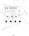
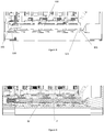
- the figures 1 and 2 represent a schematic view of a set of boxes each comprising at least one electrical device according to an embodiment of the invention.
- the whole figure 1 consists of a box 1 comprising a differential device on the right on the figure 1 and three boxes 2, 2 ', 2 "each comprising a circuit breaker module (or each an electrical device of the circuit breaker or modular circuit breaker type) to the left of the differential module.
- Each box of each modular electrical appliance (or electrical appliance) has a generally parallelepiped appearance and is delimited by two large faces F1 and F2 for example for the differential appliance 1.
- These housings form a row.
- the housing comprising the differential module 1 is positioned on the outside of the assembly, on the right on the figure 1 , and constitutes a first end housing of the assembly.
- this differential device includes a differential measurement toroid T and an actuator (capable of triggering the opening of adjacent devices in the event of a differential fault in the electrical installation to be protected.
- Three boxes 2, 2 ', 2 "circuit breakers phase-neutral type are attached to each other and to the differential module 1 housing by their large parallel faces.
- the circuit breakers D, D ', D "of the figure 1 are phase-neutral magnetothermal type.
- the housing D of the device 2 located at the left end of the row constitutes the other end housing of this row.
- This assembly has input connections E and output connection terminals S.
- the block has the particularity of distributing the 3 input phases L1, L2, L3 after their passage in the differential module , and in particular through the toroid T respectively to each of the three circuit breakers D, D ', D ".
- the neutral N is distributed after its passage in the differential module, in particular through the torus T to each of the three circuit breakers D, D ', D ".
- the neutral is distributed by a mechanical and electrical connection system SD between the output connection terminal of the differential device STN and the input connection terminal of each of the circuit breakers Em.
- the differential device includes a set of four output connection terminals ST1, ST2, ST3, STN, one for each of the three phases L1, L2, L3 and one for neutral N.
- This system thus realizes the distribution of the neutral potential between the terminal of output connection STN of the differential device 1 and the input connection terminals En of circuit breakers D, D ', D "In addition, this includes mechanical connection means (not shown) of the boxes in a row in which their large faces are joined in. In addition, in this embodiment, the assembly is such that the input connection terminals E of the differential module extend over the entire surface of the product thus formed.
- the figure 2 represents an assembly according to another embodiment of the invention similar to that of the figure 1 comprising two housings each comprising a circuit breaker type apparatus and a housing comprising a differential type apparatus.
- Another embodiment of the invention consists of an assembly comprising only boxes, each comprising a device of the circuit breaker type such as those of the figure 1 .
- the input connection terminals E are directly connected to the input connection terminals of the circuit breakers
- the neutral N is distributed to the three circuit breakers by the mechanical and electrical connection system SD which comprises connection means mechanics of the circuit breaker boxes in a row in which their large faces are joined.
- the electrical diagram of the assembly is equivalent to those described above, but the electrical and mechanical connection system distributes one of the phases L1 to L3 and keeps the various housings joined together on their large faces. 2 2 '2 "of the devices constituting said assembly.
- the term distributing a phase between two electrical devices is equivalent to electrically connecting these two devices to the same potential. All conceivable combinations are then possible, the electrical and mechanical connection system being able to distribute, neutral and / or one or more phases.
- the figure 3 represents a connector C according to an embodiment of the invention.
- This connector of the connection terminal is intended to be mechanically and electrically connected to a transverse rod 100 identical to those described in Figures 5 to 11 , this transverse rod being intended to be inserted in the connector.
- This connector is made up of two parts, one M having a generally cylindrical appearance or a sleeve intended to receive a transverse rod, the other P forming a radial protrusion of generally planar appearance, in the form of a folded or unfolded tab, and intended to be electrically and / or mechanically connected to the input or output connection terminal of the electrical devices constituting the assembly.
- the arrow F indicates the direction of insertion of the transverse rod into the sleeve.
- the sleeve consists of a sheet of conductive material, rolled on itself in order to form the peripheral wall of the sleeve of general cylindrical appearance M.
- One end of this cylinder has an expandable zone formed, in this example, by 4 tabs 10 each formed between two slots 11, 15 of axial shape formed in the peripheral wall of the sleeve, these tongues being curved towards the axis of the sleeve in order to ensure contact with the transverse rod when the latter is inserted into the sleeve M, in this example this part of the sleeve preferably has a generally frustoconical shape. Optionally (not shown) this shape can also be cylindrical.
- this expendable zone is preferably formed on the side where the transverse rod exits from the sleeve during its insertion, this in order to facilitate the insertion of the transverse rod into the sleeve.
- a chamfer 14 of the same type as the previous one can also be provided at the level of the expandable zones 10, this in order to facilitate the extraction of the transverse rod when the expandable zones are clamped on said rod.
- the sleeve includes 4 tabs.
- This number of expandable tongues can vary from one, two to as many tongues as there are contact points necessary to ensure quality electrical contact between the sleeve and the rod.
- the axial-looking slot 15 formed in the peripheral wall of the sleeve opens at the two ends of the latter, which makes it possible to manufacture the sleeve and the radial protrusion P in one piece.
- the figure 4 presents the connector of the figure 3 in a view along the axis of the sleeve M in the opposite direction to the arrow F.
- the connector is connected by the radial protrusion P to a terminal 16 input or output of an electrical apparatus of the assembly.
- This connection ensures an electrical connection between the two elements, in order to ensure the distribution of the potential of the transverse rod to the electrical device to be supplied, but also a mechanical connection between the connector C and the terminal 16 to ensure the holding C of the connector vis-à-vis the connection terminal when inserting the transverse rod into the sleeve M.
- This connection can conventionally be made by soldering with or without addition of material, by clinching or any other process assembly.
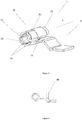
- the transverse rod 100 is in position inserted in the connector C3 and being inserted in the connectors C2 and C1. The direction and direction of insertion being always symbolized by the arrow F.
- the transverse rod is equipped with a head 101 at one of its ends.
- the head 101 has a general shape of a disc perpendicular to the axis of the rod 100, this disc being equipped with a radial groove.
- the conductor 110 is shaped in this example to pass through a measurement toroid T (not shown in this figure) in a device of the differential type.
- the ends 111 and 112 of this conductor are respectively the input and output connection terminals of the differential module.
- the connection terminal 112 corresponds to one of the connection terminals STN of the figure 1 and the connection terminal 111 corresponds to the connection terminal intended for neutral N, of the figure 1 .
- the output connection terminal 112 of the differential device is connected to the head 101 of the rod 100. This connection is provided by soldering, clinching or any other assembly process ensuring a mechanical and electrical connection between these two elements.
- the output terminal 112 of the differential device is preferably connected to the radial rib of the head 101. This link can be produced directly on the head 101 (not shown in this figure).
- a radial rib can also make it possible to block the rod 100 in rotation.
- the head 101 can also be provided with a screw head type imprint.
- the conductor 110 can be flexible or rigid.
- the other end of the rod 100 may be provided with an internal thread intended to receive the screw 102.
- the tightening of the screw 102 in the rod 100 is facilitated by the presence of the radial rib on the head 101 or by any other system allowing the blocking in rotation or the rotary drive of the rod 100 during the tightening of the screw 102 in the rod 100.
- the two elements the rod 100 and the screw 102 ensuring the mechanical maintenance of the housings comprised between the head 101 and the head of the screw 102.
- the electrical connection of the rod to the various devices being carried out by means of three connectors C1, C2, C3 and the head 101 of the rod 100. This connection could also be made by four connectors. Once the rod 100 is inserted into the connectors C1, C2, C3, these can be permanently linked to the rod by a soldering operation. Such an operation ensures an electrical connection between the rod and the various connectors. A clinching operation of the connectors on the rod would have the same effect.
- the figure 6 represents the same embodiment as that of the figure 5 , the rod 100 being in position inserted in the three connectors.
- the figure 10 is a cross section of the assembly of the figure 5 at the axis of the rod 100.
- the hole 103 is threaded to allow the assembly of the screw 102 in the rod 100.
- the rod 100 is in the position inserted in the sleeves of the connectors C1, C2, C3.
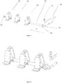
- the figure 11 is a perspective view of a transverse rod 100 according to another embodiment than that presented in the figure 10 .
- the rod 100 is provided with an external thread 104 at one of its ends and the other end is provided with a head 101.
- the thread 104 is intended to be screwed into a barrel of a first housing. .
- This screwing is possible by the presence on the face of the head 101 opposite the rod 100 of means for driving the rod 100 in rotation such as a screwing impression or a hollow or bump radial groove like that of the figure 5 .
- the part of the head 101 on the side of the rod 100 comes at the end of screwing in abutment on a wall of a housing opposite the first.
- the rod 100 allows the tightening of the housings included between the two end housings.
- the conductor 110 is electrically connected to the rod 100 by the connection terminal 112.
- the connection terminal 112 is in the form of a ring.
- the means for fixing the rod to the housings or the different versions of the head of the rod 100 are permutable and constitute only non-limiting examples of the possible solutions for producing these assemblies.
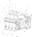
- the figure 7 is a perspective view of an electrical appliance according to the electrical diagram of the figure 1 .
- the outer cover of the differential case being removed.
- An important aspect resides in the fact that normally, such an assembly made up of several housings is mechanically assembled by means of rivets, well known from one skilled in the art. These rivets are slid into the barrels 120 and crimped so as, on the one hand, to hold each unit of the electrical appliance unitarily and on the other hand to hold the housings of the assembly together In this case the electrical distribution of a potential between the different devices must be done outside the volume occupied by the said boxes.
- the electrical and mechanical connection system according to the embodiment has the particularity of occupying the place of one of these assembly rivets, in fact it does not collide with constituent elements of the various electrical modules.
- the system therefore takes up the assembly functions of the various electrical boxes constituting the assembly and it also has the particularity of making it possible to distribute an electrical potential to each of the electrical devices. This potential distribution is carried out via the transverse rod and the various connectors C, C1, C2, C3 present in each device.
- the head 101 which represents the end of the transverse rod housed in one of the assembly drums 120.
- the assembly consisting of three circuit breaker type devices and a differential device whose housing is partially open, has four input connection terminals opening out to the lower surface (inf) of said assembly. These four terminals constitute the four input terminals of the differential device of the assembly according to the embodiment.
- each of these connection terminals has two possible connection points with an external conductor.
- the first of the four input connection terminals corresponding to input E for phase L1 of the figure 1 , has on the underside of the block (Inf) a connection point E11 intended to connect cables with the input connection terminal and a connection point E12 intended to connect rigid conductors of comb type with the terminal input L1.
- each of the input connection terminals may have only one type of connection for cable or bridging comb or may be of the spring type and not of the screw type, all combinations being possible.
- the assembly having the following particularity: the four input connection terminals extend over the entire surface Inf of the assembly constituted by the assembly of the various housings. So on the figure 7 , the connection points E11, E21, E31, E41 extend regularly spaced over the entire lower surface inf of said block. Thus the electrician operator has all this surface in order to be able to connect the various input connection terminals of said differential device to the electrical network. In addition, the input connection terminals being distributed over this entire surface, the maximum size of each conductor to be connected is thus optimized.
- each sleeve M can preferably be positioned in a barrel F made of insulating materials of the plastic type.
- this barrel has a generally hollow cylindrical shape.
- the mechanical connection system is produced by the screw 102, the rod 100 in combination with parts of the housings of the electrical devices constituting said assembly.
- the row of boxes has two end boxes, the first one to the left of the figure 8 and a second on the right of this same figure, opposite the first.
- the screw 102 screwed into the rod 100 comes to bear on a wall 120 of the housing located on the left on the figure 8
- the other end of the rod 100 comprises a head 101 which comes to bear on a wall 121 of the housing located on the right on the figure 8 and opposite the first case cited.
- the pressure generated by this assembly makes it possible to clamp between them all the housings included between the two end housings in a row in which their large faces are joined.
- two adjacent electrical devices for example the two circuit breakers contained in the boxes 2 and 2 ', are separated by a joint part (Int).
- This joint part includes the large consecutive parallel faces and facing these two housings 2 and 2 'in the row of the assembly.
- the two consecutive large parallel faces of these two consecutive boxes 2, 2 ′ of the row of the set being integrated in this adjoining room, the two consecutive and adjacent electrical devices are no longer separated by a double wall, which saves material.
- the Int part can also be positioned between the 2 'and 2 "boxes.
- the two consecutive large parallel faces of these two devices are integrated in this part.
- the figure 12 shows a partial perspective view of an assembly according to an embodiment of the invention from a viewing angle which allows the head of the screw 102 to be seen.
- This screw is accessible through a cylindrical hole 105 opening into a side wall of one of the boxes of the assembly.
- This hole allows, during the assembly of the mechanical and electrical connection system according to the embodiment, to access the head of the screw 102, this in order to carry out the screwing of the screw 102 on the rod 100.
- the hole cylindrical 105 ends with a counterbore which allows the head of the screw 102 to be supported on an end box of the assembly.
- the screw 102 being in contact with the rod 100 which distributes an electrical potential, it is therefore itself at the same electrical potential as that of the rod 100.
- the head of the screw 102 is therefore accessible to a user and presents a risk of electric shock when the apparatuses of the assembly are in service.
- One possible solution is to offset the counterbore from the bottom of the hole 105 so that the head of the screw is no longer accessible by the user's finger. In this case the head of the screw 102 remains always visible to the user and he is protected.
- Another option is the one shown in the figures 13 and 14 .
- the hole 105 is surrounded by a surface 106 parallel to the face of the housing and offset from the latter so as to allow the installation of a shutter 107. Thanks to this surface offset, the surface 106 is set back by relative to the lateral face of the housing, once in place the shutter 107 is flush with the lateral surface of the housing and is thus almost invisible and does not affect the dimension of the row of boxes as can be seen in the figure 14 .
- the shutter has a rectangular shape, the shape of the shutter has no influence on its function from the moment its surface covers the through hole 105.
Landscapes
- Breakers (AREA)
- Details Of Connecting Devices For Male And Female Coupling (AREA)
Claims (20)
- Anordnung mit einer Reihe von mindestens zwei getrennten Isoliergehäusen (1, 2, 2, 2, 2', 2"), die jeweils zwei große parallele Flächen (F1, F2) aufweisen und jeweils mindestens ein modulares elektrisches Gerät aufweisen, zum Beispiel vom Typ Leistungsschalter, Schutzschalter, Differenzialschutzschalter, wobei jedes der elektrischen Geräte mindestens einen elektrischen Verbindungsanschluss (Em, L1, L2, L3, L3, L3, L4, ST) aufweist, welche Anordnung mindestens ein mechanisches und elektrisches Verbindungssystem (SD, 100, 101, 102) umfasst, das die Gehäuse mechanisch miteinander verbindet,
wobei das System den Anschluss oder einen der Anschlüsse (ST, EM, L1, L2, L3, L4, 16) mindestens eines elektrischen Geräts mit dem Anschluss oder einem der Anschlüsse eines anderen elektrischen Geräts elektrisch verbindet, um ein elektrisches Potential zwischen diesen zu verteilen,
und wobei das System zumindest teilweise in dem durch die Gehäuse definierten Volumen aufgenommen ist,
dadurch gekennzeichnet, dass das mechanische und elektrische Verbindungssystem (SD, 100, 101, 102) die Gehäuse durch Ausübung einer Presskraft auf zwei Gehäuse in der Reihe mechanisch miteinander verbindet, welche Presskraft im Wesentlichen senkrecht zu den beiden großen parallelen Flächen (F1, F2) gerichtet ist. - Anordnung mit einer Reihe aus mindestens zwei getrennten Isoliergehäusen nach dem vorhergehenden Anspruch, dadurch gekennzeichnet, dass die Reihe zwei Endgehäuse (1, 2) aufweist, nämlich ein erstes Endgehäuse (1) an einem Ende der Reihe und ein zweites Endgehäuse (2) am anderen Ende der Reihe,
wobei das mechanische und elektrische Verbindungssystem (SD, 100, 101, 102) die Gehäuse unter anderem durch Ausübung einer Presskraft mechanisch miteinander verbindet, welche Presskraft im Wesentlichen senkrecht zu den beiden großen parallelen Flächen (F1, F2) an den Endgehäusen gerichtet ist. - Anordnung nach einem der vorhergehenden Ansprüche, dadurch gekennzeichnet, dass das mechanische und elektrische Verbindungssystem (SD, 100, 101, 102) vollständig in dem durch die Gehäuse definierten Volumen aufgenommen ist.
- Anordnung nach einem der vorhergehenden Ansprüche, dadurch gekennzeichnet, dass jedes der elektrischen Geräte mindestens einen elektrischen Eingangs-Verbindungsanschluss und mindestens einen elektrischen Ausgangs-Verbindungsanschluss aufweist, wobei das mechanische und elektrische Verbindungssystem (SD, 100, 101, 102) mindestens einen Ausgangs-Verbindungsanschluss (112) wenigstens eines ersten elektrischen Geräts mit mindestens einem Eingangs-Verbindungsanschluss (Em, 16, 111) wenigstens eines anderen elektrischen Geräts elektrisch verbindet.
- Anordnung nach einem der Ansprüche 1 bis 3, dadurch gekennzeichnet, dass jedes der elektrischen Geräte mindestens einen elektrischen Eingangs-Verbindungsanschluss und mindestens einen elektrischen Ausgangs-Verbindungsanschluss umfasst, und dass das Verbindungssystem (SD, 100, 101, 102) wenigstens zwei elektrische Eingangs-Verbindungsanschlüsse (Em, 16, 111) von mindestens zwei elektrischen Geräten elektrisch verbindet.
- Anordnung nach einem der vorhergehenden Ansprüche, dadurch gekennzeichnet, dass das mechanische und elektrische Verbindungssystem (SD, 100, 101, 102) eine Querstange (100) umfasst, wobei jeder der elektrischen Eingangs- und/oder Ausgangs-Verbindungsanschlüsse wenigstens eines elektrischen Geräts der Anordnung einen Verbinder (C, 112) innerhalb des/der Gehäuse(s) umfasst, wobei die Stange (100) dazu ausgebildet ist, mit den elektrischen Verbindern (C, 112) innerhalb der Gehäuse verbunden zu werden.
- Anordnung nach dem vorhergehenden Anspruch, dadurch gekennzeichnet, dass mindestens einer der Verbinder (C, 112) mit dem mechanischen und elektrischen Verbindungssystem (SD, 100, 101, 102), vorzugsweise mit der Querstange (100), verlötet ist.
- Anordnung nach einem der Ansprüche 6 und 7, dadurch gekennzeichnet, dass mindestens einer der Verbinder (C) aus einer zylindrischen leitfähigen Hülse (M) gebildet ist, die mindestens eine unter der Einwirkung der Querstange (100) bei deren Einführung in die Hülse nach außen vergrößerbare Zone (10) aufweist, wobei die Hülse (M) außerdem mit einem äußeren radialen Vorsprung (P) versehen ist, der an einem Eingangs- oder Ausgangsanschluss einer der elektrischen Geräte befestigt ist.
- Anordnung nach dem vorhergehenden Anspruch, dadurch gekennzeichnet, dass jede vergrößerbare Zone (10) zwischen zwei axialen Schlitzen (11) in der Umfangswand der Hülse (M) ausgebildet ist.
- Anordnung nach dem vorhergehenden Anspruch, dadurch gekennzeichnet, dass einer der axialen Schlitze (15) derart ausgebildet ist, dass er zu beiden Enden der Hülse (M) öffnet, wobei der äußere Vorsprung (P) integral mit einem der Ränder des Schlitzes ausgebildet ist.
- Anordnung nach einem der Ansprüche 8 bis 10, dadurch gekennzeichnet, dass die vergrößerbare(n) Zone(n) (10) in einem Abschnitt der Hülse (M) ausgebildet ist/sind, in dem diese kegelstumpfförmig ausgebildet ist.
- Anordnung nach einem der Ansprüche 8 bis 11, dadurch gekennzeichnet, dass die beiden axialen Enden der Hülse angefast (12, 14) sind.
- Anordnung nach einem der Ansprüche 8 bis 12, dadurch gekennzeichnet, dass die Hülsen (M) jeweils in einem Behälter (F) aus Isoliermaterial vom Typ Kunststoff angeordnet sind, wobei der Behälter (F) Teil eines der Isoliergehäuse ist und die vergrößerbaren Zonen (10) einen Druck auf die Innenwand des Behälters ausüben, wenn die Querstange (100) dort eingeführt ist.
- Anordnung nach einem der Ansprüche 6 bis 13, dadurch gekennzeichnet, dass die Querstange (100) an einem Ende einen Kopf (101) aufweist, der mit Mitteln zum Antreiben der Stange in einer Drehbewegung versehen ist, beispielsweise vom Typ eines Schraubenkopfs, wobei der Kopf (101) an einer Seitenwand (121) eines Isoliergehäuses in der Reihe anliegt, vorzugsweise eines der beiden Endgehäuse (1, 2).
- Anordnung nach einem der Ansprüche 6 bis 14, dadurch gekennzeichnet, dass die Querstange (100) einen der Position des Kopfes (101) gegenüberliegenden Gewindeendabschnitt (104) zum Einschrauben in ein Gewinde aufweist, das in einer Seitenwand eines der Isoliergehäuse (1, 2, 2', 2") angeordnet ist.
- Anordnung nach einem der Ansprüche 6 bis 14, dadurch gekennzeichnet, dass die Querstange (100) einen Gewindeendabschnitt im Inneren der Stange (103) gegenüber dem Kopf der Stange (101) aufweist, wobei die Anordnung ferner eine Schraube (102) umfasst, die in dem Gewindeendabschnitt aufgenommen ist, wobei die Schraube (102) an einer Seitenwand (120) eines der Isoliergehäuse (1, 2, 2', 2") anliegt.
- Anordnung nach einem der vorhergehenden Ansprüche, dadurch gekennzeichnet, dass eines der elektrischen Geräte ein Differenzialmodul (1) ist, das mindestens einen elektrischen Ausgangs-Verbindungsanschluss (ST, 112) umfasst, wobei mindestens eines der anderen elektrischen Geräte ein Schutzschalter (2) ist, der mindestens einen elektrischen Eingangs-Verbindungsanschluss (Em, 16) umfasst, wobei das mechanische und elektrische Verbindungssystem (SD, 100, 101, 102) einen elektrischen Ausgangs-Verbindungsanschluss (ST, 112) mit mindestens einem elektrischen Eingangs-Verbindungsanschluss (Em, 16) verbindet.
- Anordnung nach dem vorhergehenden Anspruch, dadurch gekennzeichnet, dass sie vier elektrische Geräte umfasst, zum Beispiel vom Typ Leistungsschalter, Schutzschalter, Differenzialschutzschalter, und dadurch, dass eines der elektrischen Geräte ein Differenzialmodul (1) mit mindestens einem elektrischen Ausgangs-Verbindungsanschluss (ST, 112) ist, wobei die anderen drei elektrischen Geräte Schutzschalter (2, 2', 2") sind, die jeweils mindestens einen elektrischen Eingangs-Verbindungsanschluss (Em, 16) aufweisen, wobei das mechanische und elektrische Verbindungssystem (SD, 100, 101, 101, 101, 102) einen elektrischen Ausgangs-Verbindungsanschluss (ST, 112) mit mindestens einem elektrischen Eingangs-Verbindungsanschluss (Em, 16) jedes der Schutzschalter verbindet, um ein elektrisches Potential zwischen diesen zu verteilen.
- Anordnung nach einem der Ansprüche 17 bis 18, dadurch gekennzeichnet, dass sich die elektrischen Eingangsanschlüsse (E11, E21, E31, E41) des Differenzialmoduls über eine ganze Fläche (inf) der Anordnung erstrecken.
- Anordnung nach einem der vorhergehenden Ansprüche, dadurch gekennzeichnet, dass die beiden großen parallelen Flächen (F1, F2) von mindestens zwei aufeinanderfolgenden Gehäusen der Reihe (2, 2'), (2', 2"), (2", 1) aus einem an die beiden aufeinanderfolgenden Kästen der Reihe angrenzenden Teil (Int) bestehen.
Applications Claiming Priority (2)
| Application Number | Priority Date | Filing Date | Title |
|---|---|---|---|
| FR1557439A FR3039698B1 (fr) | 2015-07-31 | 2015-07-31 | Ensemble de boitiers d'appareils electriques mecaniquement et electriquement relies entre eux |
| PCT/FR2016/051957 WO2017021623A1 (fr) | 2015-07-31 | 2016-07-28 | Ensemble de boîtiers d'appareils electriques mecaniquement et electriquement relies entre eux |
Publications (2)
| Publication Number | Publication Date |
|---|---|
| EP3300530A1 EP3300530A1 (de) | 2018-04-04 |
| EP3300530B1 true EP3300530B1 (de) | 2020-02-19 |
Family
ID=55345895
Family Applications (1)
| Application Number | Title | Priority Date | Filing Date |
|---|---|---|---|
| EP16756726.2A Active EP3300530B1 (de) | 2015-07-31 | 2016-07-28 | Anordnung von mechanisch und elektrisch verbundenen gehäusen elektrischer vorrichtungen |
Country Status (4)
| Country | Link |
|---|---|
| EP (1) | EP3300530B1 (de) |
| CN (1) | CN107924793B (de) |
| FR (1) | FR3039698B1 (de) |
| WO (1) | WO2017021623A1 (de) |
Families Citing this family (3)
| Publication number | Priority date | Publication date | Assignee | Title |
|---|---|---|---|---|
| CN108054067A (zh) * | 2017-12-06 | 2018-05-18 | 俊朗电气有限公司 | 一种小型自动重合闸 |
| CN108321041A (zh) * | 2018-02-06 | 2018-07-24 | 俊朗电气有限公司 | 一种模块化设计取电装置 |
| FR3103626B1 (fr) * | 2019-11-21 | 2022-07-08 | Hager Electro Sas | Système électromécanique d’interruption d’un courant électrique |
Family Cites Families (8)
| Publication number | Priority date | Publication date | Assignee | Title |
|---|---|---|---|---|
| DE7105414U (de) * | 1971-02-13 | 1971-05-06 | Bbc Ag | Mehrpoliger Fehlerstromschutzschalter |
| CH672859A5 (en) * | 1987-03-27 | 1989-12-29 | Maier & Cie C | Terminal arrangement for fault protection switch - has input current terminals and neutral terminals in separate planes w.r.t. front face |
| FR2841376B1 (fr) * | 2002-06-25 | 2004-08-06 | Schneider Electric Ind Sa | Ensemble de protection et de commande electromagnetique |
| EP1432001B1 (de) | 2002-12-20 | 2008-06-11 | Hager Electro | Elektrisches Gerät, beispielsweise modulares elektrisches Gerät mit einem zweiteiligen Gehäuse |
| DE602007006940D1 (de) * | 2007-07-26 | 2010-07-15 | Bticino Spa | Differentialschutzblock für einen elektrischen Schalter |
| JP5084779B2 (ja) * | 2008-11-27 | 2012-11-28 | 東京エレクトロン株式会社 | プラグインユニット |
| US9196441B2 (en) * | 2013-04-19 | 2015-11-24 | Abl Ip Holding Llc | Modular relay sub-assembly |
| DE112014003884T5 (de) * | 2013-08-23 | 2016-05-12 | Mitsubishi Electric Corporation | Antriebsvorrichtung |
-
2015
- 2015-07-31 FR FR1557439A patent/FR3039698B1/fr not_active Expired - Fee Related
-
2016
- 2016-07-28 EP EP16756726.2A patent/EP3300530B1/de active Active
- 2016-07-28 CN CN201680043787.7A patent/CN107924793B/zh active Active
- 2016-07-28 WO PCT/FR2016/051957 patent/WO2017021623A1/fr not_active Ceased
Non-Patent Citations (1)
| Title |
|---|
| None * |
Also Published As
| Publication number | Publication date |
|---|---|
| FR3039698B1 (fr) | 2019-08-30 |
| FR3039698A1 (fr) | 2017-02-03 |
| CN107924793A (zh) | 2018-04-17 |
| CN107924793B (zh) | 2020-04-07 |
| WO2017021623A1 (fr) | 2017-02-09 |
| EP3300530A1 (de) | 2018-04-04 |
Similar Documents
| Publication | Publication Date | Title |
|---|---|---|
| CA2871272C (fr) | Module de stockage d'energie contenant une pluralite d'elements de stockage d'energie et des moyens de dissipation thermique perfectionnes et procede d'assemblage | |
| EP1376638B1 (de) | Elektromagnetischer Schutz und Steuereinheit | |
| EP3300530B1 (de) | Anordnung von mechanisch und elektrisch verbundenen gehäusen elektrischer vorrichtungen | |
| EP2146400B1 (de) | Verbindungseinheit und Montageverfahren einer solchen Verbindungseinheit | |
| EP2849287A1 (de) | Elektrische Anschlussvorrichtung mit mindestens einem Leiter in einer Klemme, die zu einem elektrischen Gerät gehört | |
| EP2299552A1 (de) | Gehäuse zur Aufnahme eines Niedrigspannungsgeräts, das mit einer Schaltgerätzelle mittlerer Spannung verbunden ist | |
| FR2899023A1 (fr) | Perfectionnements introduits dans les systemes de connexion par interverrouillage applicables aux dispositifs electriques | |
| EP3227966A1 (de) | Elektrisches verbindungselement, das einen stromdrahtisolierungsmantel penetriert | |
| FR2919764A1 (fr) | Dispositif de raccordement electrique entre deux cellules a moyenne ou haute tension et poste de distribution comportant au moins un tel dispositif | |
| FR2797353A1 (fr) | Connecteur electrique utlisant des organes penetrant dans l'isolation | |
| FR2990570A1 (fr) | Embout de branchement pour cable d'alimentation electrique isole et procede de fabrication de cet embout de branchement | |
| EP3409084B1 (de) | Kabelbaumanschlussplatte | |
| FR2926393A1 (fr) | Bloc de transformation d'un declencheur electronique a double passage | |
| EP0860901B1 (de) | Gehäuse für elektrischen Gerät und elektrische Vorrichtung mit einem solchen Gehäuse | |
| FR2802024A1 (fr) | Repartiteur modulaire monopolaire et bloc de connexion pour un tel repartiteur | |
| EP3349305B1 (de) | Verbessertes elektrisches anschlusskit | |
| FR3028356A1 (fr) | Borne de connexion electrique a vis imperdable | |
| EP3709445A1 (de) | Elektrischer schalter für elektrisches gerät | |
| EP2439815B1 (de) | Anordnung bestehend aus einem Kabelkanal und einer elektrische Verbindungsvorrichtung | |
| FR2900508A1 (fr) | Barre omnibus pour repartition electrique | |
| EP2068411A1 (de) | Elektrische Einbau-Ausrüstung mit Schnellanschluss | |
| EP3435398B1 (de) | Elektrisches differentialschutzgerät | |
| EP3312948B1 (de) | Elektrische steckdose, die ein monoblockteil zur halterung und aufnahme von höckereinsätzen umfasst, und verfahren zum zusammenbau einer solchen elektrischen steckdose | |
| EP4557526A1 (de) | Leistungsanschlussmodul zum klemmen eines elektrischen kabelabschlusses durch ein blatt, dessen mindestens ein verformbares teil zur bildung eines anschlussblockteils einer verbindungsanordnung bildet | |
| FR2948823A1 (fr) | Connecteur, grille de fausse coupure comprenant un tel connecteur et coffret de raccordement equipe d'une telle grille |
Legal Events
| Date | Code | Title | Description |
|---|---|---|---|
| STAA | Information on the status of an ep patent application or granted ep patent |
Free format text: STATUS: THE INTERNATIONAL PUBLICATION HAS BEEN MADE |
|
| PUAI | Public reference made under article 153(3) epc to a published international application that has entered the european phase |
Free format text: ORIGINAL CODE: 0009012 |
|
| STAA | Information on the status of an ep patent application or granted ep patent |
Free format text: STATUS: REQUEST FOR EXAMINATION WAS MADE |
|
| 17P | Request for examination filed |
Effective date: 20171228 |
|
| AK | Designated contracting states |
Kind code of ref document: A1 Designated state(s): AL AT BE BG CH CY CZ DE DK EE ES FI FR GB GR HR HU IE IS IT LI LT LU LV MC MK MT NL NO PL PT RO RS SE SI SK SM TR |
|
| AX | Request for extension of the european patent |
Extension state: BA ME |
|
| RIN1 | Information on inventor provided before grant (corrected) |
Inventor name: SCHMITT, CEDRIC Inventor name: HECHT, JEAN GEORGES Inventor name: CHARLES, BENJAMIN |
|
| RAP1 | Party data changed (applicant data changed or rights of an application transferred) |
Owner name: HAGER-ELECTRO SAS |
|
| DAV | Request for validation of the european patent (deleted) | ||
| DAX | Request for extension of the european patent (deleted) | ||
| GRAP | Despatch of communication of intention to grant a patent |
Free format text: ORIGINAL CODE: EPIDOSNIGR1 |
|
| STAA | Information on the status of an ep patent application or granted ep patent |
Free format text: STATUS: GRANT OF PATENT IS INTENDED |
|
| INTG | Intention to grant announced |
Effective date: 20191111 |
|
| GRAS | Grant fee paid |
Free format text: ORIGINAL CODE: EPIDOSNIGR3 |
|
| GRAA | (expected) grant |
Free format text: ORIGINAL CODE: 0009210 |
|
| STAA | Information on the status of an ep patent application or granted ep patent |
Free format text: STATUS: THE PATENT HAS BEEN GRANTED |
|
| AK | Designated contracting states |
Kind code of ref document: B1 Designated state(s): AL AT BE BG CH CY CZ DE DK EE ES FI FR GB GR HR HU IE IS IT LI LT LU LV MC MK MT NL NO PL PT RO RS SE SI SK SM TR |
|
| REG | Reference to a national code |
Ref country code: CH Ref legal event code: EP |
|
| REG | Reference to a national code |
Ref country code: DE Ref legal event code: R096 Ref document number: 602016030126 Country of ref document: DE |
|
| REG | Reference to a national code |
Ref country code: AT Ref legal event code: REF Ref document number: 1235908 Country of ref document: AT Kind code of ref document: T Effective date: 20200315 |
|
| REG | Reference to a national code |
Ref country code: IE Ref legal event code: FG4D Free format text: LANGUAGE OF EP DOCUMENT: FRENCH |
|
| REG | Reference to a national code |
Ref country code: NL Ref legal event code: FP |
|
| REG | Reference to a national code |
Ref country code: CH Ref legal event code: NV Representative=s name: DR. GRAF AND PARTNER AG INTELLECTUAL PROPERTY, CH |
|
| PG25 | Lapsed in a contracting state [announced via postgrant information from national office to epo] |
Ref country code: RS Free format text: LAPSE BECAUSE OF FAILURE TO SUBMIT A TRANSLATION OF THE DESCRIPTION OR TO PAY THE FEE WITHIN THE PRESCRIBED TIME-LIMIT Effective date: 20200219 Ref country code: NO Free format text: LAPSE BECAUSE OF FAILURE TO SUBMIT A TRANSLATION OF THE DESCRIPTION OR TO PAY THE FEE WITHIN THE PRESCRIBED TIME-LIMIT Effective date: 20200519 Ref country code: FI Free format text: LAPSE BECAUSE OF FAILURE TO SUBMIT A TRANSLATION OF THE DESCRIPTION OR TO PAY THE FEE WITHIN THE PRESCRIBED TIME-LIMIT Effective date: 20200219 |
|
| REG | Reference to a national code |
Ref country code: LT Ref legal event code: MG4D |
|
| PG25 | Lapsed in a contracting state [announced via postgrant information from national office to epo] |
Ref country code: IS Free format text: LAPSE BECAUSE OF FAILURE TO SUBMIT A TRANSLATION OF THE DESCRIPTION OR TO PAY THE FEE WITHIN THE PRESCRIBED TIME-LIMIT Effective date: 20200619 Ref country code: HR Free format text: LAPSE BECAUSE OF FAILURE TO SUBMIT A TRANSLATION OF THE DESCRIPTION OR TO PAY THE FEE WITHIN THE PRESCRIBED TIME-LIMIT Effective date: 20200219 Ref country code: LV Free format text: LAPSE BECAUSE OF FAILURE TO SUBMIT A TRANSLATION OF THE DESCRIPTION OR TO PAY THE FEE WITHIN THE PRESCRIBED TIME-LIMIT Effective date: 20200219 Ref country code: SE Free format text: LAPSE BECAUSE OF FAILURE TO SUBMIT A TRANSLATION OF THE DESCRIPTION OR TO PAY THE FEE WITHIN THE PRESCRIBED TIME-LIMIT Effective date: 20200219 Ref country code: BG Free format text: LAPSE BECAUSE OF FAILURE TO SUBMIT A TRANSLATION OF THE DESCRIPTION OR TO PAY THE FEE WITHIN THE PRESCRIBED TIME-LIMIT Effective date: 20200519 Ref country code: GR Free format text: LAPSE BECAUSE OF FAILURE TO SUBMIT A TRANSLATION OF THE DESCRIPTION OR TO PAY THE FEE WITHIN THE PRESCRIBED TIME-LIMIT Effective date: 20200520 |
|
| PG25 | Lapsed in a contracting state [announced via postgrant information from national office to epo] |
Ref country code: DK Free format text: LAPSE BECAUSE OF FAILURE TO SUBMIT A TRANSLATION OF THE DESCRIPTION OR TO PAY THE FEE WITHIN THE PRESCRIBED TIME-LIMIT Effective date: 20200219 Ref country code: EE Free format text: LAPSE BECAUSE OF FAILURE TO SUBMIT A TRANSLATION OF THE DESCRIPTION OR TO PAY THE FEE WITHIN THE PRESCRIBED TIME-LIMIT Effective date: 20200219 Ref country code: SM Free format text: LAPSE BECAUSE OF FAILURE TO SUBMIT A TRANSLATION OF THE DESCRIPTION OR TO PAY THE FEE WITHIN THE PRESCRIBED TIME-LIMIT Effective date: 20200219 Ref country code: LT Free format text: LAPSE BECAUSE OF FAILURE TO SUBMIT A TRANSLATION OF THE DESCRIPTION OR TO PAY THE FEE WITHIN THE PRESCRIBED TIME-LIMIT Effective date: 20200219 Ref country code: ES Free format text: LAPSE BECAUSE OF FAILURE TO SUBMIT A TRANSLATION OF THE DESCRIPTION OR TO PAY THE FEE WITHIN THE PRESCRIBED TIME-LIMIT Effective date: 20200219 Ref country code: CZ Free format text: LAPSE BECAUSE OF FAILURE TO SUBMIT A TRANSLATION OF THE DESCRIPTION OR TO PAY THE FEE WITHIN THE PRESCRIBED TIME-LIMIT Effective date: 20200219 Ref country code: RO Free format text: LAPSE BECAUSE OF FAILURE TO SUBMIT A TRANSLATION OF THE DESCRIPTION OR TO PAY THE FEE WITHIN THE PRESCRIBED TIME-LIMIT Effective date: 20200219 Ref country code: SK Free format text: LAPSE BECAUSE OF FAILURE TO SUBMIT A TRANSLATION OF THE DESCRIPTION OR TO PAY THE FEE WITHIN THE PRESCRIBED TIME-LIMIT Effective date: 20200219 Ref country code: PT Free format text: LAPSE BECAUSE OF FAILURE TO SUBMIT A TRANSLATION OF THE DESCRIPTION OR TO PAY THE FEE WITHIN THE PRESCRIBED TIME-LIMIT Effective date: 20200712 |
|
| REG | Reference to a national code |
Ref country code: AT Ref legal event code: MK05 Ref document number: 1235908 Country of ref document: AT Kind code of ref document: T Effective date: 20200219 |
|
| REG | Reference to a national code |
Ref country code: DE Ref legal event code: R097 Ref document number: 602016030126 Country of ref document: DE |
|
| PLBE | No opposition filed within time limit |
Free format text: ORIGINAL CODE: 0009261 |
|
| STAA | Information on the status of an ep patent application or granted ep patent |
Free format text: STATUS: NO OPPOSITION FILED WITHIN TIME LIMIT |
|
| 26N | No opposition filed |
Effective date: 20201120 |
|
| PG25 | Lapsed in a contracting state [announced via postgrant information from national office to epo] |
Ref country code: IT Free format text: LAPSE BECAUSE OF FAILURE TO SUBMIT A TRANSLATION OF THE DESCRIPTION OR TO PAY THE FEE WITHIN THE PRESCRIBED TIME-LIMIT Effective date: 20200219 Ref country code: AT Free format text: LAPSE BECAUSE OF FAILURE TO SUBMIT A TRANSLATION OF THE DESCRIPTION OR TO PAY THE FEE WITHIN THE PRESCRIBED TIME-LIMIT Effective date: 20200219 |
|
| PG25 | Lapsed in a contracting state [announced via postgrant information from national office to epo] |
Ref country code: MC Free format text: LAPSE BECAUSE OF FAILURE TO SUBMIT A TRANSLATION OF THE DESCRIPTION OR TO PAY THE FEE WITHIN THE PRESCRIBED TIME-LIMIT Effective date: 20200219 Ref country code: PL Free format text: LAPSE BECAUSE OF FAILURE TO SUBMIT A TRANSLATION OF THE DESCRIPTION OR TO PAY THE FEE WITHIN THE PRESCRIBED TIME-LIMIT Effective date: 20200219 Ref country code: SI Free format text: LAPSE BECAUSE OF FAILURE TO SUBMIT A TRANSLATION OF THE DESCRIPTION OR TO PAY THE FEE WITHIN THE PRESCRIBED TIME-LIMIT Effective date: 20200219 |
|
| GBPC | Gb: european patent ceased through non-payment of renewal fee |
Effective date: 20200728 |
|
| REG | Reference to a national code |
Ref country code: BE Ref legal event code: MM Effective date: 20200731 |
|
| PG25 | Lapsed in a contracting state [announced via postgrant information from national office to epo] |
Ref country code: LU Free format text: LAPSE BECAUSE OF NON-PAYMENT OF DUE FEES Effective date: 20200728 Ref country code: GB Free format text: LAPSE BECAUSE OF NON-PAYMENT OF DUE FEES Effective date: 20200728 |
|
| PG25 | Lapsed in a contracting state [announced via postgrant information from national office to epo] |
Ref country code: BE Free format text: LAPSE BECAUSE OF NON-PAYMENT OF DUE FEES Effective date: 20200731 |
|
| PG25 | Lapsed in a contracting state [announced via postgrant information from national office to epo] |
Ref country code: IE Free format text: LAPSE BECAUSE OF NON-PAYMENT OF DUE FEES Effective date: 20200728 |
|
| PG25 | Lapsed in a contracting state [announced via postgrant information from national office to epo] |
Ref country code: TR Free format text: LAPSE BECAUSE OF FAILURE TO SUBMIT A TRANSLATION OF THE DESCRIPTION OR TO PAY THE FEE WITHIN THE PRESCRIBED TIME-LIMIT Effective date: 20200219 Ref country code: MT Free format text: LAPSE BECAUSE OF FAILURE TO SUBMIT A TRANSLATION OF THE DESCRIPTION OR TO PAY THE FEE WITHIN THE PRESCRIBED TIME-LIMIT Effective date: 20200219 Ref country code: CY Free format text: LAPSE BECAUSE OF FAILURE TO SUBMIT A TRANSLATION OF THE DESCRIPTION OR TO PAY THE FEE WITHIN THE PRESCRIBED TIME-LIMIT Effective date: 20200219 |
|
| PG25 | Lapsed in a contracting state [announced via postgrant information from national office to epo] |
Ref country code: MK Free format text: LAPSE BECAUSE OF FAILURE TO SUBMIT A TRANSLATION OF THE DESCRIPTION OR TO PAY THE FEE WITHIN THE PRESCRIBED TIME-LIMIT Effective date: 20200219 Ref country code: AL Free format text: LAPSE BECAUSE OF FAILURE TO SUBMIT A TRANSLATION OF THE DESCRIPTION OR TO PAY THE FEE WITHIN THE PRESCRIBED TIME-LIMIT Effective date: 20200219 |
|
| P01 | Opt-out of the competence of the unified patent court (upc) registered |
Effective date: 20230606 |
|
| PGFP | Annual fee paid to national office [announced via postgrant information from national office to epo] |
Ref country code: NL Payment date: 20250726 Year of fee payment: 10 |
|
| PGFP | Annual fee paid to national office [announced via postgrant information from national office to epo] |
Ref country code: DE Payment date: 20250729 Year of fee payment: 10 |
|
| PGFP | Annual fee paid to national office [announced via postgrant information from national office to epo] |
Ref country code: FR Payment date: 20250728 Year of fee payment: 10 |
|
| PGFP | Annual fee paid to national office [announced via postgrant information from national office to epo] |
Ref country code: CH Payment date: 20250801 Year of fee payment: 10 |