EP1432071A2 - Kompakte und Kleinprofileantennenvorrichtung mit breitem Resonanzfrequenzbereich - Google Patents
Kompakte und Kleinprofileantennenvorrichtung mit breitem Resonanzfrequenzbereich Download PDFInfo
- Publication number
- EP1432071A2 EP1432071A2 EP03257819A EP03257819A EP1432071A2 EP 1432071 A2 EP1432071 A2 EP 1432071A2 EP 03257819 A EP03257819 A EP 03257819A EP 03257819 A EP03257819 A EP 03257819A EP 1432071 A2 EP1432071 A2 EP 1432071A2
- Authority
- EP
- European Patent Office
- Prior art keywords
- conductor plate
- radiating conductor
- antenna device
- radiating
- capacitive
- Prior art date
- Legal status (The legal status is an assumption and is not a legal conclusion. Google has not performed a legal analysis and makes no representation as to the accuracy of the status listed.)
- Withdrawn
Links
Images


Classifications
-
- H—ELECTRICITY
- H01—ELECTRIC ELEMENTS
- H01Q—ANTENNAS, i.e. RADIO AERIALS
- H01Q21/00—Antenna arrays or systems
- H01Q21/30—Combinations of separate antenna units operating in different wavebands and connected to a common feeder system
-
- H—ELECTRICITY
- H01—ELECTRIC ELEMENTS
- H01Q—ANTENNAS, i.e. RADIO AERIALS
- H01Q5/00—Arrangements for simultaneous operation of antennas on two or more different wavebands, e.g. dual-band or multi-band arrangements
- H01Q5/30—Arrangements for providing operation on different wavebands
- H01Q5/307—Individual or coupled radiating elements, each element being fed in an unspecified way
- H01Q5/342—Individual or coupled radiating elements, each element being fed in an unspecified way for different propagation modes
- H01Q5/357—Individual or coupled radiating elements, each element being fed in an unspecified way for different propagation modes using a single feed point
- H01Q5/364—Creating multiple current paths
- H01Q5/371—Branching current paths
-
- H—ELECTRICITY
- H01—ELECTRIC ELEMENTS
- H01Q—ANTENNAS, i.e. RADIO AERIALS
- H01Q9/00—Electrically-short antennas having dimensions not more than twice the operating wavelength and consisting of conductive active radiating elements
- H01Q9/04—Resonant antennas
- H01Q9/30—Resonant antennas with feed to end of elongated active element, e.g. unipole
- H01Q9/32—Vertical arrangement of element
- H01Q9/36—Vertical arrangement of element with top loading
-
- H—ELECTRICITY
- H01—ELECTRIC ELEMENTS
- H01Q—ANTENNAS, i.e. RADIO AERIALS
- H01Q9/00—Electrically-short antennas having dimensions not more than twice the operating wavelength and consisting of conductive active radiating elements
- H01Q9/04—Resonant antennas
- H01Q9/30—Resonant antennas with feed to end of elongated active element, e.g. unipole
- H01Q9/42—Resonant antennas with feed to end of elongated active element, e.g. unipole with folded element, the folded parts being spaced apart a small fraction of the operating wavelength
Definitions
- the present invention relates to a compact and low-profile antenna device suitable for being incorporated in in-car communication devices.
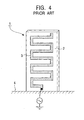
- Antenna devices having a meandering radiating conductor formed on the surface of a substrate by patterning, as shown in Fig. 4, have been known as compact and low-profile antennas which can be incorporated in in-car communication devices (refer to, for example, Japanese Unexamined Patent Application Publication No. 2000-349532, in particular, pages 3 to 4 and Fig. 1).
- a meandering radiating conductor 3 composed of a copper film is disposed on the surface of a dielectric substrate 2, which is vertically mounted on a ground conductor plate 4.
- Predetermined high-frequency power is fed to the bottom end of the radiating conductor 3 via a feed line, such as a coaxial cable.
- the radiating conductor 3 formed in a zigzag meandering shape has a significantly decreased height compared to a radiating conductor formed in a straight shape having the same electrical length, thereby advantageously reducing the profile of the whole body of the antenna.
- antenna devices having a radiating conductor composed of two connected meandering lines with different pitches on the surface of a substrate, as shown in Fig. 5, have been known as compact antennas which are capable of transmitting or receiving signal waves in two frequency bands (refer to, for example, Japanese Unexamined Patent Application Publication No. 2001-68918, in particular, pages 3 to 4 and Fig. 1).
- a radiating conductor 8 composed of a copper film is formed, by patterning, on the surface of a dielectric substrate 7 which is vertically mounted on a ground conductor plate 6, and the radiating conductor 8 is formed such that a first radiating conductor portion 8a, which extends from the vicinity of a feed point in a meandering fashion with a relatively wide pitch, is connected to a second radiating conductor portion 8b, which extends from the top of the first radiating conductor portion 8a in a meandering fashion with a relatively narrow pitch.
- the whole radiating conductor 8 from the first radiating conductor portion 8a to the second radiating conductor portion 8b can be resonated at a first frequency f 1 .
- the first radiating conductor portion 8a can be resonated at a second frequency f 2 which is higher than the first frequency f 1 . That is, since hardly any higher frequency electrical current flows in the meandering line with the narrow pitch (the second radiating conductor portion 8b), only the first radiating conductor portion 8a can be operated as a radiating element for the second frequency f 2 .
- the radiating conductors 3 and 8 may be composed of narrower ribbons.
- the narrow radiating conductors 3 and 8 cause a narrow resonance frequency band, making it difficult to reduce the profile of the antenna devices 1 and 5 while ensuring a sufficient frequency bandwidth.
- the two radiating conductor portions 8a and 8b having different meander pitches are connected in series. Consequently, the length of the radiating conductor 8 becomes long, thus making it difficult to reduce the profile of the whole body of the antenna.
- an object of the present invention to provide an antenna device having a wide resonance frequency band and allowing for easy reduction of the size and the height. It is a second object of the present invention to provide a dual-band antenna device having a wide resonance frequency band and allowing for easy reduction of the size and the height.
- an antenna device includes a radiating conductor plate composed of a metal ribbon having a predetermined width that is folded a plurality of times so as to meander and a supporting substrate having a ground conductor thereon, wherein the radiating conductor plate is vertically mounted on the supporting substrate and high-frequency power is fed to the bottom end of the radiating conductor plate.
- the radiating conductor plate composed of a metal ribbon folded to meander can be folded a large number of times within a limited height without excessively decreasing the meander pitch.
- the radiating conductor plate advantageously allows for easy reduction of the size and the height, compared to a radiating conductor formed in a meandering shape by patterning.
- the radiating conductor plate can advantageously have sufficient width to provide a wide frequency band.
- the antenna device is advantageously cost-effective.
- the antenna device may include a capacitive conductor plate disposed substantially parallel to the ground conductor and connected to the top end of the radiating conductor plate and a connection conductor plate for electrically shorting the capacitive conductor plate to the ground conductor.
- the capacitive conductor plate functions as a shortening or loading capacitor, thereby decreasing the resonance frequency of the radiating conductor plate. Consequently, the electrical length of the radiating conductor plate required for resonating at a predetermined frequency becomes short, thereby further decreasing the height of the antenna device.
- the capacitive conductor plate is shorted to the ground conductor via a connection conductor plate, impedance mismatching is avoided.
- the top end of the radiating conductor plate is connected to substantially the center of the capacitive conductor plate so as to obtain a high antenna gain in the horizontal direction.
- the radiating conductor plate may be composed of a folded metal ribbon that is a cut and bent portion of a flat metal sheet and the capacitive conductor plate may be composed of the remaining portion of the metal sheet.
- the radiating conductor plate and the capacitive conductor plate may be formed from a single metal sheet by a pressing process. A soldering operation that connects and fixes the both conductor plates together is not required, and so the antenna device can be manufactured at a low cost.
- the antenna device includes a second radiating conductor plate extending upwardly in a vertical direction and being connected to the bottom end of the above-described radiating conductor plate, wherein high-frequency power that has a higher frequency than that of the above-described high-frequency power is fed to the bottom end of the second radiating conductor plate.
- the second radiating conductor plate can operate as a monopole antenna whose electrical length is much shorter than that of the above-described meandering radiating conductor plate. Therefore, the meandering radiating conductor plate functions as a radiating element resonating at the first resonance frequency while the second radiating conductor plate functions as a radiating element resonating at a second frequency that is higher than the first resonance frequency. Accordingly, a high-performance dual-band antenna allowing for easy reduction of the size and the height can be obtained.
- Fig. 1 is a perspective view of an antenna device according to a first embodiment of the present invention.
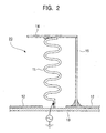
- Fig. 2 is a side elevation view of an antenna device according to a second embodiment of the present invention.
- Fig. 3 is a perspective view of an antenna device according to a third embodiment of the present invention.
- An antenna device 10 shown in Fig. 1 includes a meandering radiating conductor plate 11 composed of a metal conductor plate, for example, a copper plate, having a predetermined width that is folded a plurality of times and a supporting substrate 13 having a ground conductor 12, wherein the radiating conductor plate 11 is vertically mounted on the supporting substrate 13 and high-frequency power is fed to the bottom end of the radiating conductor plate 11.
- the radiating conductor plate 11 is folded so as to meander with a meander pitch sufficient to suppress high-order modes by a bending process.
- the ground conductor 12 is composed of a conductive film such as a copper film, which is formed over substantially the entire surface of the insulating supporting substrate 13.
- the electrical length of the radiating conductor plate 11 is set to about one fourth of the selected wavelength so that the antenna device 10 can transmit or receive radio waves in a resonance frequency band by feeding predetermined high-frequency power to the radiating conductor plate 11 to excite it.
- the radiating conductor plate 11 composed of a metal ribbon folded in a meandering fashion can be folded a large number of times within a limited height without excessively decreasing the meander pitch. As a result, the height of the thin radiating conductor plate 11 does not increase while ensuring the required electrical length and a sufficient meander pitch to suppress high-order modes. Therefore, the size and the height of the antenna device 10 can easily be reduced.
- the radiating conductor plate 11 has sufficient width to provide a wide resonance frequency band, and hence the antenna device 10 provides a wide frequency band and ease of use. Since the radiating conductor plate 11 is easily manufactured from a metal conductor plate such as a copper plate by pressing, the antenna device 10 is advantageously cost-effective.
- the main difference between an antenna device 20 shown in Fig. 2 and the antenna device 10 according to the first embodiment is as follows: in the structure of the antenna device 20, a capacitive conductor plate 14 disposed parallel to a ground conductor 12 is electrically and mechanically connected to the top end of a radiating conductor plate 11 and the capacitive conductor plate 14 is electrically shorted to the ground conductor 12 via a connection conductor plate 15.
- the capacitive conductor plate 14 is composed of a metal conductor plate like a copper plate, which is the same material as the radiating conductor plate 11.
- the top end of the radiating conductor plate 11 is soldered to substantially the center of the capacitive conductor plate 14.
- the connection conductor plate 15 is mounted at an appropriate position where impedance mismatching can be avoided.
- a metal ribbon downwardly extending from the capacitive conductor plate 14 serves as the connection conductor plate 15.
- the capacitive conductor plate 14 functions as a shortening capacitor, thereby decreasing the resonance frequency of the radiating conductor plate 11. Consequently, the electrical length of the radiating conductor plate 11 required for resonating at a predetermined frequency becomes short, thereby decreasing the height of the antenna device. Further, since the top end of the radiating conductor plate 11 is connected to substantially the center of the capacitive conductor plate 14, the antenna device 20 has a high antenna gain in the horizontal direction, thereby providing high-sensitivity transmission and reception in the horizontal direction.
- a straight radiating conductor plate 16 is formed from a rising section of a ribbon which extends from the bottom end of the meandering radiating conductor plate 11.
- the straight radiating conductor plate 16 resonates at a second frequency f 2 that is higher than a first resonance frequency f 1 of the radiating conductor plate 11. That is, the straight radiating conductor plate 16 operates as a monopole antenna whose electrical length is much shorter than that of the meandering radiating conductor plate 11.
- the one radiating conductor plate 11 functions as a radiating element resonating at the first resonance frequency f 1 while the other radiating conductor plate 16 functions as a radiating element resonating at a second frequency f 2 that is higher than the first resonance frequency f 1 . Accordingly, the antenna device 30 is an excellent dual-band antenna allowing for easy reduction of the size and the height and having a wide frequency band.
- the meandering radiating conductor plate 11 is composed of a folded metal ribbon that is a cut and bent portion of a flat metal sheet and the capacitive conductor plate 14 is composed of the remaining portion of the metal sheet. Accordingly, the capacitive conductor plate 14, the radiating conductor plate 11, and the straight radiating conductor plate 16 can be formed from a single metal sheet by a pressing process. A soldering operation that connects and fixes the conductor plates 14, 11, and 16 together is not required so that the antenna device 30, even though it is a dual-band antenna, can be manufactured at a relatively low cost.
Landscapes
- Details Of Aerials (AREA)
- Waveguide Aerials (AREA)
- Variable-Direction Aerials And Aerial Arrays (AREA)
Applications Claiming Priority (2)
| Application Number | Priority Date | Filing Date | Title |
|---|---|---|---|
| JP2002363888A JP2004200772A (ja) | 2002-12-16 | 2002-12-16 | アンテナ装置 |
| JP2002363888 | 2002-12-16 |
Publications (2)
| Publication Number | Publication Date |
|---|---|
| EP1432071A2 true EP1432071A2 (de) | 2004-06-23 |
| EP1432071A3 EP1432071A3 (de) | 2004-07-07 |
Family
ID=32376207
Family Applications (1)
| Application Number | Title | Priority Date | Filing Date |
|---|---|---|---|
| EP03257819A Withdrawn EP1432071A3 (de) | 2002-12-16 | 2003-12-12 | Kompakte und Kleinprofileantennenvorrichtung mit breitem Resonanzfrequenzbereich |
Country Status (3)
| Country | Link |
|---|---|
| US (1) | US20040155832A1 (de) |
| EP (1) | EP1432071A3 (de) |
| JP (1) | JP2004200772A (de) |
Cited By (3)
| Publication number | Priority date | Publication date | Assignee | Title |
|---|---|---|---|---|
| WO2006125925A1 (fr) * | 2005-05-27 | 2006-11-30 | Thomson Licensing | Antenne monopole |
| CN102396104A (zh) * | 2009-11-30 | 2012-03-28 | 纽帕尔斯有限公司 | 具有垂直定向的辐射器的内置天线及其制造方法 |
| CN108604732A (zh) * | 2015-11-17 | 2018-09-28 | 深谷波股份公司 | 自接地可表面安装的蝴蝶结天线组件、天线瓣及制造方法 |
Families Citing this family (52)
| Publication number | Priority date | Publication date | Assignee | Title |
|---|---|---|---|---|
| TWI239122B (en) * | 2004-04-29 | 2005-09-01 | Ind Tech Res Inst | Omnidirectional broadband monopole antenna |
| JP4623272B2 (ja) * | 2004-09-02 | 2011-02-02 | ミツミ電機株式会社 | アンテナ装置 |
| US10992185B2 (en) | 2012-07-06 | 2021-04-27 | Energous Corporation | Systems and methods of using electromagnetic waves to wirelessly deliver power to game controllers |
| US9876394B1 (en) | 2014-05-07 | 2018-01-23 | Energous Corporation | Boost-charger-boost system for enhanced power delivery |
| US10256657B2 (en) | 2015-12-24 | 2019-04-09 | Energous Corporation | Antenna having coaxial structure for near field wireless power charging |
| US10992187B2 (en) | 2012-07-06 | 2021-04-27 | Energous Corporation | System and methods of using electromagnetic waves to wirelessly deliver power to electronic devices |
| US9787103B1 (en) | 2013-08-06 | 2017-10-10 | Energous Corporation | Systems and methods for wirelessly delivering power to electronic devices that are unable to communicate with a transmitter |
| US10063105B2 (en) | 2013-07-11 | 2018-08-28 | Energous Corporation | Proximity transmitters for wireless power charging systems |
| US9867062B1 (en) | 2014-07-21 | 2018-01-09 | Energous Corporation | System and methods for using a remote server to authorize a receiving device that has requested wireless power and to determine whether another receiving device should request wireless power in a wireless power transmission system |
| US10965164B2 (en) | 2012-07-06 | 2021-03-30 | Energous Corporation | Systems and methods of wirelessly delivering power to a receiver device |
| US9825674B1 (en) | 2014-05-23 | 2017-11-21 | Energous Corporation | Enhanced transmitter that selects configurations of antenna elements for performing wireless power transmission and receiving functions |
| US11502551B2 (en) | 2012-07-06 | 2022-11-15 | Energous Corporation | Wirelessly charging multiple wireless-power receivers using different subsets of an antenna array to focus energy at different locations |
| US12057715B2 (en) | 2012-07-06 | 2024-08-06 | Energous Corporation | Systems and methods of wirelessly delivering power to a wireless-power receiver device in response to a change of orientation of the wireless-power receiver device |
| US10312715B2 (en) | 2015-09-16 | 2019-06-04 | Energous Corporation | Systems and methods for wireless power charging |
| KR101481287B1 (ko) * | 2013-07-01 | 2015-01-14 | 현대자동차주식회사 | 이동통신 서비스를 위한 차량용 안테나 |
| US10778041B2 (en) | 2015-09-16 | 2020-09-15 | Energous Corporation | Systems and methods for generating power waves in a wireless power transmission system |
| US11710321B2 (en) | 2015-09-16 | 2023-07-25 | Energous Corporation | Systems and methods of object detection in wireless power charging systems |
| US10734717B2 (en) | 2015-10-13 | 2020-08-04 | Energous Corporation | 3D ceramic mold antenna |
| US10063108B1 (en) * | 2015-11-02 | 2018-08-28 | Energous Corporation | Stamped three-dimensional antenna |
| US10038332B1 (en) | 2015-12-24 | 2018-07-31 | Energous Corporation | Systems and methods of wireless power charging through multiple receiving devices |
| US11863001B2 (en) | 2015-12-24 | 2024-01-02 | Energous Corporation | Near-field antenna for wireless power transmission with antenna elements that follow meandering patterns |
| US10079515B2 (en) | 2016-12-12 | 2018-09-18 | Energous Corporation | Near-field RF charging pad with multi-band antenna element with adaptive loading to efficiently charge an electronic device at any position on the pad |
| JP2016226056A (ja) * | 2016-10-04 | 2016-12-28 | 株式会社デンソーウェーブ | アンテナ装置 |
| US10923954B2 (en) | 2016-11-03 | 2021-02-16 | Energous Corporation | Wireless power receiver with a synchronous rectifier |
| JP6691273B2 (ja) | 2016-12-12 | 2020-04-28 | エナージャス コーポレイション | 配送される無線電力を最大化するために近接場充電パッドのアンテナ区域を選択的に活性化する方法 |
| WO2018110671A1 (ja) * | 2016-12-16 | 2018-06-21 | 株式会社ヨコオ | アンテナ装置 |
| US10680319B2 (en) | 2017-01-06 | 2020-06-09 | Energous Corporation | Devices and methods for reducing mutual coupling effects in wireless power transmission systems |
| US10439442B2 (en) | 2017-01-24 | 2019-10-08 | Energous Corporation | Microstrip antennas for wireless power transmitters |
| WO2018183892A1 (en) | 2017-03-30 | 2018-10-04 | Energous Corporation | Flat antennas having two or more resonant frequencies for use in wireless power transmission systems |
| US10511097B2 (en) | 2017-05-12 | 2019-12-17 | Energous Corporation | Near-field antennas for accumulating energy at a near-field distance with minimal far-field gain |
| US12074460B2 (en) | 2017-05-16 | 2024-08-27 | Wireless Electrical Grid Lan, Wigl Inc. | Rechargeable wireless power bank and method of using |
| US11462949B2 (en) | 2017-05-16 | 2022-10-04 | Wireless electrical Grid LAN, WiGL Inc | Wireless charging method and system |
| US12074452B2 (en) | 2017-05-16 | 2024-08-27 | Wireless Electrical Grid Lan, Wigl Inc. | Networked wireless charging system |
| US10848853B2 (en) | 2017-06-23 | 2020-11-24 | Energous Corporation | Systems, methods, and devices for utilizing a wire of a sound-producing device as an antenna for receipt of wirelessly delivered power |
| US11342798B2 (en) | 2017-10-30 | 2022-05-24 | Energous Corporation | Systems and methods for managing coexistence of wireless-power signals and data signals operating in a same frequency band |
| EP3503293B1 (de) * | 2017-12-19 | 2024-12-11 | Institut Mines Telecom - IMT Atlantique - Bretagne - Pays de la Loire | Konfigurierbare mehrbanddrahtantennenanordnung und designverfahren dafür |
| US11437735B2 (en) | 2018-11-14 | 2022-09-06 | Energous Corporation | Systems for receiving electromagnetic energy using antennas that are minimally affected by the presence of the human body |
| KR20210117283A (ko) | 2019-01-28 | 2021-09-28 | 에너저스 코포레이션 | 무선 전력 전송을 위한 소형 안테나에 대한 시스템들 및 방법들 |
| JP2022519749A (ja) | 2019-02-06 | 2022-03-24 | エナージャス コーポレイション | アンテナアレイ内の個々のアンテナに使用するための最適位相を推定するシステム及び方法 |
| US12155231B2 (en) | 2019-04-09 | 2024-11-26 | Energous Corporation | Asymmetric spiral antennas for wireless power transmission and reception |
| WO2021055901A1 (en) | 2019-09-20 | 2021-03-25 | Energous Corporation | Asymmetric spiral antennas with parasitic elements for wireless power transmission |
| WO2021055900A1 (en) | 2019-09-20 | 2021-03-25 | Energous Corporation | Classifying and detecting foreign objects using a power amplifier controller integrated circuit in wireless power transmission systems |
| US11381118B2 (en) | 2019-09-20 | 2022-07-05 | Energous Corporation | Systems and methods for machine learning based foreign object detection for wireless power transmission |
| US11411441B2 (en) | 2019-09-20 | 2022-08-09 | Energous Corporation | Systems and methods of protecting wireless power receivers using multiple rectifiers and establishing in-band communications using multiple rectifiers |
| WO2021055898A1 (en) | 2019-09-20 | 2021-03-25 | Energous Corporation | Systems and methods for machine learning based foreign object detection for wireless power transmission |
| US11355966B2 (en) | 2019-12-13 | 2022-06-07 | Energous Corporation | Charging pad with guiding contours to align an electronic device on the charging pad and efficiently transfer near-field radio-frequency energy to the electronic device |
| US10985617B1 (en) | 2019-12-31 | 2021-04-20 | Energous Corporation | System for wirelessly transmitting energy at a near-field distance without using beam-forming control |
| US11799324B2 (en) | 2020-04-13 | 2023-10-24 | Energous Corporation | Wireless-power transmitting device for creating a uniform near-field charging area |
| US11469629B2 (en) | 2020-08-12 | 2022-10-11 | Energous Corporation | Systems and methods for secure wireless transmission of power using unidirectional communication signals from a wireless-power-receiving device |
| US12306285B2 (en) | 2020-12-01 | 2025-05-20 | Energous Corporation | Systems and methods for using one or more sensors to detect and classify objects in a keep-out zone of a wireless-power transmission field, and antennas with integrated sensor arrangements |
| US11916398B2 (en) | 2021-12-29 | 2024-02-27 | Energous Corporation | Small form-factor devices with integrated and modular harvesting receivers, and shelving-mounted wireless-power transmitters for use therewith |
| US12142939B2 (en) | 2022-05-13 | 2024-11-12 | Energous Corporation | Integrated wireless-power-transmission platform designed to operate in multiple bands, and multi-band antennas for use therewith |
Family Cites Families (9)
| Publication number | Priority date | Publication date | Assignee | Title |
|---|---|---|---|---|
| US2566491A (en) * | 1946-03-15 | 1951-09-04 | Belmont Radio Corp | Antenna construction |
| US5181044A (en) * | 1989-11-15 | 1993-01-19 | Matsushita Electric Works, Ltd. | Top loaded antenna |
| DE4205851C2 (de) * | 1992-02-26 | 1995-10-12 | Flachglas Ag | In die Fensteröffnung einer metallischen Kraftfahrzeugkarosserie einzusetzende Antennenscheibe |
| US5600339A (en) * | 1994-12-06 | 1997-02-04 | Oros; Edward A. | Antenna |
| SE515504C2 (sv) * | 1999-11-29 | 2001-08-20 | Smarteq Wireless Ab | Kapacitivt belastad antenn och ett antennaggregat |
| DE10114012B4 (de) * | 2000-05-11 | 2011-02-24 | Amtran Technology Co., Ltd., Chung Ho | Chipantenne |
| US6459413B1 (en) * | 2001-01-10 | 2002-10-01 | Industrial Technology Research Institute | Multi-frequency band antenna |
| DE20106005U1 (de) * | 2001-04-05 | 2001-08-30 | RecepTec GmbH, 31135 Hildesheim | Antennenmodul, insbesondere für Frequenzen im GHz-Bereich zum Einsatz in Kraftfahrzeugen, vorzugsweise für einen Dualband- bzw. Multibandfunkbetrieb |
| JP3651594B2 (ja) * | 2001-10-24 | 2005-05-25 | 日本電気株式会社 | アンテナ素子 |
-
2002
- 2002-12-16 JP JP2002363888A patent/JP2004200772A/ja not_active Withdrawn
-
2003
- 2003-12-12 EP EP03257819A patent/EP1432071A3/de not_active Withdrawn
- 2003-12-15 US US10/737,488 patent/US20040155832A1/en not_active Abandoned
Cited By (6)
| Publication number | Priority date | Publication date | Assignee | Title |
|---|---|---|---|---|
| WO2006125925A1 (fr) * | 2005-05-27 | 2006-11-30 | Thomson Licensing | Antenne monopole |
| FR2886468A1 (fr) * | 2005-05-27 | 2006-12-01 | Thomson Licensing Sa | Antenne monopole |
| CN102396104A (zh) * | 2009-11-30 | 2012-03-28 | 纽帕尔斯有限公司 | 具有垂直定向的辐射器的内置天线及其制造方法 |
| CN108604732A (zh) * | 2015-11-17 | 2018-09-28 | 深谷波股份公司 | 自接地可表面安装的蝴蝶结天线组件、天线瓣及制造方法 |
| EP3378123A4 (de) * | 2015-11-17 | 2019-06-19 | Gapwaves AB | Selbstgeerdete oberflächenmontierbare bowtie-antennenanordnung, antennenblatt und herstellungsverfahren |
| US10720709B2 (en) | 2015-11-17 | 2020-07-21 | Gapwaves Ab | Self-grounded surface mountable bowtie antenna arrangement, an antenna petal and a fabrication method |
Also Published As
| Publication number | Publication date |
|---|---|
| US20040155832A1 (en) | 2004-08-12 |
| EP1432071A3 (de) | 2004-07-07 |
| JP2004200772A (ja) | 2004-07-15 |
Similar Documents
| Publication | Publication Date | Title |
|---|---|---|
| EP1432071A2 (de) | Kompakte und Kleinprofileantennenvorrichtung mit breitem Resonanzfrequenzbereich | |
| US6603430B1 (en) | Handheld wireless communication devices with antenna having parasitic element | |
| US6809687B2 (en) | Monopole antenna that can easily be reduced in height dimension | |
| JP4231867B2 (ja) | 無線装置および電子機器 | |
| EP1263083B1 (de) | Invertierte F-Antenne und tragbares Kommunikationsgerät mit einer solchen Antenne | |
| US5451966A (en) | Ultra-high frequency, slot coupled, low-cost antenna system | |
| US6946997B2 (en) | Dual band antenna allowing easy reduction of size and height | |
| US20050057401A1 (en) | Small-size, low-height antenna device capable of easily ensuring predetermined bandwidth | |
| US20050057416A1 (en) | Small-size, low-height antenna device capable of easily ensuring predetermined bandwidth | |
| US20050035919A1 (en) | Multi-band printed dipole antenna | |
| EP0790666A1 (de) | Kombinierte Struktur einer Helixantenne und einer dielektrischen Platte | |
| US9660347B2 (en) | Printed coupled-fed multi-band antenna and electronic system | |
| JP2003163528A (ja) | プリント回路板、表面実装装置アンテナ及び通信装置 | |
| JP4169696B2 (ja) | 高バンド幅マルチバンド・アンテナ | |
| US7173567B2 (en) | Antenna | |
| US7106253B2 (en) | Compact antenna device | |
| EP1363359A1 (de) | Ein Antennenmodul | |
| JPH07303005A (ja) | 車両用アンテナ装置 | |
| KR101049724B1 (ko) | 독립 조절이 가능하고 절곡부를 가지는 다중 대역 안테나 | |
| US20040125033A1 (en) | Dual-band antenna having high horizontal sensitivity | |
| JPH1041741A (ja) | 送受信装置 | |
| JPH09232854A (ja) | 移動無線機用小型平面アンテナ装置 | |
| JP5006000B2 (ja) | 多周波共用アンテナ | |
| JP2000134029A (ja) | アンテナ装置および通信装置 | |
| JPH04369902A (ja) | 車載アンテナ |
Legal Events
| Date | Code | Title | Description |
|---|---|---|---|
| PUAI | Public reference made under article 153(3) epc to a published international application that has entered the european phase |
Free format text: ORIGINAL CODE: 0009012 |
|
| PUAL | Search report despatched |
Free format text: ORIGINAL CODE: 0009013 |
|
| AK | Designated contracting states |
Kind code of ref document: A2 Designated state(s): AT BE BG CH CY CZ DE DK EE ES FI FR GB GR HU IE IT LI LU MC NL PT RO SE SI SK TR |
|
| AX | Request for extension of the european patent |
Extension state: AL LT LV MK |
|
| AK | Designated contracting states |
Kind code of ref document: A3 Designated state(s): AT BE BG CH CY CZ DE DK EE ES FI FR GB GR HU IE IT LI LU MC NL PT RO SE SI SK TR |
|
| AX | Request for extension of the european patent |
Extension state: AL LT LV MK |
|
| 17P | Request for examination filed |
Effective date: 20040823 |
|
| 17Q | First examination report despatched |
Effective date: 20041222 |
|
| AKX | Designation fees paid |
Designated state(s): DE FI FR GB |
|
| STAA | Information on the status of an ep patent application or granted ep patent |
Free format text: STATUS: THE APPLICATION HAS BEEN WITHDRAWN |
|
| 18W | Application withdrawn |
Effective date: 20060313 |