EP1432111A2 - Steuerungsverfahren und Vorrichtung für einen Ultraschallmotor sowie Ultraschallmotor-Steuerungsvorrichtung - Google Patents
Steuerungsverfahren und Vorrichtung für einen Ultraschallmotor sowie Ultraschallmotor-Steuerungsvorrichtung Download PDFInfo
- Publication number
- EP1432111A2 EP1432111A2 EP03257767A EP03257767A EP1432111A2 EP 1432111 A2 EP1432111 A2 EP 1432111A2 EP 03257767 A EP03257767 A EP 03257767A EP 03257767 A EP03257767 A EP 03257767A EP 1432111 A2 EP1432111 A2 EP 1432111A2
- Authority
- EP
- European Patent Office
- Prior art keywords
- driving
- displacement
- targeted
- velocity
- normative
- Prior art date
- Legal status (The legal status is an assumption and is not a legal conclusion. Google has not performed a legal analysis and makes no representation as to the accuracy of the status listed.)
- Withdrawn
Links
Images







Classifications
-
- H—ELECTRICITY
- H02—GENERATION; CONVERSION OR DISTRIBUTION OF ELECTRIC POWER
- H02N—ELECTRIC MACHINES NOT OTHERWISE PROVIDED FOR
- H02N2/00—Electric machines in general using piezoelectric effect, electrostriction or magnetostriction
- H02N2/02—Electric machines in general using piezoelectric effect, electrostriction or magnetostriction producing linear motion, e.g. actuators; Linear positioners ; Linear motors
- H02N2/06—Drive circuits; Control arrangements or methods
- H02N2/062—Small signal circuits; Means for controlling position or derived quantities, e.g. for removing hysteresis
Definitions
- the present invention relates to a control method and apparatus of an ultrasonic motor, and an ultrasonic motor driver and controller, especially to a control method and apparatus of an ultrasonic motor, and an ultrasonic motor driver and controller enabling to control accurately the displacement and/or the velocity of a driven object driven by the ultrasonic motor.
- An ultrasonic motor consists of a piezoelectric element, which makes elastic movement when a voltage is applied across the piezoelectric element, and an elastic body, which transfers the elastic motion of the piezoelectric element to a driven object driven by the ultrasonic motor.
- the ultrasonic motor drives the driven object linearly, by applying an alternative voltage to vibrate the piezoelectric element with the elastic body contacting to the driven object.
- the ultrasonic motor drives the driven object linearly, by applying an alternative voltage to vibrate the piezoelectric element with the elastic body contacting to the driven object.
- the above-mentioned control method cannot accurately control the displacement and/or the velocity of the driven object, because of the characteristic difference between individual ultrasonic motors and the difference of contacting status of the ultrasonic motor to the driven object.
- an object of the present invention to provide a control method and apparatus of an ultrasonic motor enabling to control accurately the displacement and/or the velocity of a driven object driven by an ultrasonic motor.
- a control apparatus of an ultrasonic motor comprising: a driving pulse receiving means for receiving one or a plurality of driving pulses to energize an ultrasonic motor which drives a driven object every predetermined interval; a normative driving wave generating means for generating continuously normative driving waves, the numbers of which are equal to the numbers of driving pulses received at the driving pulse receiving means multiplied by a predetermined number; and a driving wave generating means for generating driving waves having a predetermined frequency and a predetermined amplitude based on the normative driving waves generated at the normative driving wave generating means.
- the controller of the ultrasonic motor thus constructed can accurately displace the driven object, because the driving waves are supplied every a predetermined interval.
- a control apparatus of an ultrasonic motor comprising: a driving wave number determining means for determining a driving wave number based on the targeted displacement of a driven object driven by the ultrasonic motor; a normative driving wave generating means for generating continuously normative driving waves in the number of times determined at the driving wave number determining means, inserted an interval determined based on the targeted velocity of the driven object, every at least one cycle of the normative driving waves; and a driving wave generating means for generating driving waves having the predetermined frequency and the predetermined amplitude based on the normative driving waves generated at the normative driving wave generating means.
- the normative driving wave generating means may make the interval longer as the targeted velocity of the driven object is smaller.
- the controller of the ultrasonic motor thus constructed can accurately displace the driven object based on the targeted displacement, because the driving waves in the number of times determined based on the targeted displacement are supplied every a predetermined interval.
- a control apparatus of an ultrasonic motor comprising; a displacement deviation calculating means for calculating a displacement deviation defined by a deviation between the targeted displacement of a driven object driven by the ultrasonic motor and the actual displacement of the driven object; a driving wave number determining means for determining a driving wave number based on the displacement deviation calculated at the displacement deviation calculating means; a normative driving wave generating means for generating continuously normative driving waves in the number of times determined at the driving wave number determining means, inserted an interval determined based on the targeted velocity of the driven object, every at least one cycle of the normative driving waves; and a driving wave generating means for generating driving waves having the predetermined frequency and the predetermined amplitude based on the normative driving waves generated at the normative driving wave generating means.
- the normative driving wave generating means may make the interval longer as the targeted velocity of the driven object is smaller.
- the controller of the ultrasonic motor thus constructed can accurately control the displacement of the driven object so that the actual displacement corresponds to the targeted displacement, because the driving waves in the number of times determined based on the displacement deviation are supplied every a predetermined interval.
- a control apparatus of an ultrasonic motor comprising; a displacement deviation calculating means for calculating a displacement deviation defined by a deviation between the targeted displacement of a driven object driven by the ultrasonic motor and the actual displacement of the driven object; a driving wave number determining means for determining a driving wave number based on the displacement deviation calculated at the displacement deviation calculating means; a velocity deviation calculating means for calculating a velocity deviation defined by a deviation between the targeted velocity of the driven object and the actual velocity of the driven object; a normative driving wave generating means for generating continuously normative driving waves in the number of times determined at the driving wave number determining means, inserted an interval determined based on the velocity deviation calculated at the velocity deviation calculating means, every at least one cycle of the normative driving waves; and a driving wave generating means for generating driving waves having the predetermined frequency and the predetermined amplitude based on the normative driving waves generated at the normative driving wave generating means.
- the normative driving wave generating means may make the interval longer as the targeted velocity of the driven object is smaller.
- the controller of the ultrasonic motor thus constructed can accurately control the displacement and velocity of the driven object so that the actual displacement and velocity correspond to the targeted displacement and velocity, because the driving waves in the number of times determined based on the displacement deviation are supplied every a interval determined based on the velocity deviation.
- an ultrasonic motor driver comprising: a driving pulse receiving part to receive one or a plurality of driving pulses to energize an ultrasonic motor which drives a driven object every predetermined interval; a multiplier setting part to set a multiplier; a manual-mode normative driving wave generating part to generate continuously manual-mode normative driving waves, the numbers of which are equal to the numbers of driving pulses received at the driving pulse receiving part multiplied by the multiplier set at the multiplier setting part; a targeted displacement receiving part to receive a targeted displacement of the driven object; a displacement deviation calculating part to calculate a displacement deviation defined by a deviation between the targeted displacement received by the targeted displacement receiving part and the actual displacement of the driven object; a displacement control signal choosing part to choose between the targeted displacement received by said targeted displacement receiving part and the displacement deviation calculated by the displacement deviation calculating part, as a displacement control signal; a driving wave number determining part to determine a driving wave number based on the displacement control signal chose by the displacement feedback signal
- the normative driving wave generating part may make the interval longer as the targeted velocity of the driven object is smaller.
- the driving wave generating part may include either at least one of a frequency changing part to change the frequency of the normative driving waves and an amplitude changing part to change the amplitude of the normative driving waves.
- the ultrasonic motor controller such constructed can accurately control the driving number of times and the operating velocity of the ultrasonic motor driving the driven object.
- an ultrasonic motor controller comprising: an ultrasonic motor driver comprised of a driving pulse receiving part to receive one or a plurality of driving pulses to energize an ultrasonic motor which drives a driven object every predetermined interval, a multiplier setting part to set a multiplier, a manual-mode normative driving wave generating part to generate continuously manual-mode normative driving waves, the numbers of which are equal to the numbers of driving pulses received at the driving pulse receiving part multiplied by the multiplier set at the multiplier setting part, a targeted displacement receiving part to receive a targeted displacement of the driven object, a displacement deviation calculating part to calculate a displacement deviation defined by a deviation between the targeted displacement received by the targeted displacement receiving part and the actual displacement of the driven object, a displacement control signal choosing part to choose between the targeted displacement received by the targeted displacement receiving part and the displacement deviation calculated by said displacement deviation calculating part, based on a displacement control choosing signal, a driving wave number determining part to determine driving wave number based on
- the normative driving wave generating part may make the interval longer as the targeted velocity of the driven object is smaller.
- the driving wave generating part may include either at least one of a frequency changing part to change the frequency of the normative driving waves and an amplitude changing part to change the amplitude of the normative driving waves.
- the ultrasonic motor controller thus constructed can accurately control the displacement and velocity of the driven object driven by the ultrasonic motor.
- a first embodiment of a control apparatus 1 of an ultrasonic motor includes a driving pulse receiving means 101 for receiving one or a plurality of driving pulses to energize an ultrasonic motor 62, which drives a driven object 61 every predetermined interval, a normative driving wave generating means 102 for generating continuously normative driving waves, the numbers of which are equal to the numbers of driving pulses received at the driving pulse receiving means 101 multiplied by a predetermined multiplier, and a driving wave generating means 11 for generating driving waves having a predetermined frequency and a predetermined amplitude based on the normative driving waves generated at the normative driving wave generating means 102.
- the control apparatus is comprised of a microprocessor 10, which works as the driving pulse receiving means 101 and the normative driving wave generating means 102, and the driving wave generating means 11 is comprised of discrete elements.
- the driving wave generating means 11 includes a frequency-changing unit 111 and an amplitude-changing unit 112.
- the microprocessor 10 also works as a targeted frequency setting unit 103 and a targeted amplitude setting unit 104.
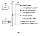
- the microprocessor 10 consists of a CPU 10b, a memory 10c, and an interfaces 10d, which are connected each other by a bus 10a.
- the microprocessor 10 fetches driving pulses through the interface 10d, and outputs normative driving waves, and the targeted frequency and the targeted amplitude of the normative driving waves.
- the driving pulses are generated at a driving pulse generating part 63, which consists of a rotary encoder, for example, and are transmitted to the driving pulse receiving means 101 in the microprocessor 10.through the interface 10d.
- a multiplier is output from a multiplier setting part 64, which consists of a potentiometer, for example, and is transmitted to the normative driving wave generating means 102 in the microprocessor 10 through the interface 10d.
- the frequency-changing unit 111 in the driving wave generating means is configured so as to generate the driving waves based on the normative driving waves generated at the normative driving wave generating means 102.
- the frequency changing unit 111 is configured so that the frequency of the driving waves can be changed by changing the targeted frequency set at the targeted amplitude setting part 103.
- the amplitude-changing unit 112 in the driving wave generating means 11 is configured so as to generate a first driving waves having the same phase as the driving waves generated at the frequency-changing unit 111, and a second driving waves having a phase difference in 90 degrees to the driving waves in order to amplify the first driving waves and the second driving waves supplied to the ultrasonic motor 62.
- the amplitude-changing unit 112 is configured so that the amplitude of the amplified first and second driving waves can be changed by changing the targeted amplitude set at the targeted amplitude setting part 104.
- the first and second driving waves output from the amplitude-changing unit 112 are supplied to the piezoelectric element of the ultrasonic motor 62.
- the piezoelectric element moves elliptically, and drives the driven object 61 linearly.
- the wave pattern of the normative driving waves generated at the normative driving wave generating means assumes the pattern of 1000 continuous driving waves to which a one second interval is added if the multiplier m is 10.
- a second embodiment of a control apparatus of an ultrasonic motor according to the present invention 2 includes a driving wave number determining means 105 for determining a driving wave number based on the targeted displacement of a driven object 61 driven by the ultrasonic motor 62, a normative driving wave generating means 102 for generating continuously normative driving waves in the number of times determined at the driving wave number determining means 105, inserted an interval determined based on the targeted velocity of the driven object 61, every at least one cycle of the normative driving waves, and a driving wave generating means 11 for generating driving waves having the predetermined frequency and the predetermined amplitude based on the normative driving waves generated at the normative driving wave generating means 102.
- the control apparatus consists of a microprocessor 10, which works as the driving wave number determining means 105 and the normative driving wave generating means 102, and the driving wave generating means 11 consisting of discrete elements.
- the driving wave generating means 11 includes a frequency-changing unit 111 and an amplitude-changing unit 112.
- the microprocessor 10 also works as a targeted frequency setting part 103 and a targeted amplitude setting part 104.
- microprocessor 10 of this embodiment has the same configuration as the first embodiment, the explanation of the configuration of the microprocessor 10 is omitted.
- the microprocessor 10 fetches a targeted displacement and a targeted velocity of the driven object 61 and outputs the normative driving waves, the targeted frequency and the targeted amplitude through the interface 10d.
- the targeted displacement Xd is transferred from the targeted displacement setting part 65 consisting of a rotary encoder to the driving wave number determining means 105 in the microprocessor 10 through the interface 10d.
- the targeted velocity Vd is transferred from the targeted velocity setting part 66 consisting of another rotary encoder to the normative driving wave generating means 102 in the microprocessor 10 through the interface 10d.
- the interval D is a decreasing function of the targeted velocity Vd.
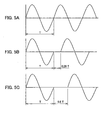
- the period of the normative driving wave is defined as T
- h is a decreasing function of the targeted velocity Vd.
- the normative driving wave generating means 102 is configured so as to insert the interval D determined based on equation (4), every at least one cycle of the normative driving waves.
- the microprocessor 10 executes the control program represented by the flowchart of FIG. 4, and works as the driving wave number determining means 105, the normative driving wave generating means 102, the targeted frequency setting means 103, and the targeted amplitude setting means 104.
- the microprocessor 10 fetches the targeted displacement Xd from the targeted displacement setting part 65 at step S41, and determines the driving wave number based on the targeted displacement Xd at step S42.
- the microprocessor 10 fetches the targeted velocity Vd from the targeted velocity setting part 66 at step S43, and generates the normative driving waves in which the interval determined based on the targeted velocity Vd every at least one cycle of the normative driving waves at step S44.
- the microprocessor 10 outputs the normative driving waves at step S45, the targeted frequency at step S46, and the targeted amplitude at step S47.
- the interval may be inserted every two cycles of the normative driving waves as shown in FIG. 6A, and may be inserted every four cycles of the normative driving waves as shown in FIG. 6B.
- the driving wave generating means 11 of this embodiment has the same configuration and function as the first embodiment, the explanation is omitted.
- a third embodiment of a control apparatus of an ultrasonic motor according to the present invention 3 includes a displacement deviation calculating means 106 for calculating a displacement deviation defined by a deviation between the targeted displacement of a driven object 61 driven by the ultrasonic motor 62 and the actual displacement of the driven object 61, a driving wave number determining means 105 for determining a driving wave number based on the displacement deviation calculated at the displacement deviation calculating means 106, a normative driving wave generating means 102 for generating continuously normative driving waves in the number of times determined at the driving wave number determining means 105, inserted an interval determined based on the targeted velocity of the driven object 61, every at least one cycle of the normative driving waves, and a driving wave generating means 11 for generating driving waves having the predetermined frequency and the predetermined amplitude based on the normative driving waves generated at the normative driving wave generating means 102.
- the control apparatus consists of a microprocessor 10, which works as the displacement deviation calculating means 106, the driving wave number determining means 105 and the normative driving wave generating means 102, and the driving wave generating means 11 consisting of discrete elements.
- the driving wave generating means 11 includes a frequency-changing unit 111 and an amplitude-changing unit 112.
- the microprocessor 10 also works as a frequency setting part 103 and an amplitude setting part 104.
- the targeted displacement Xd is transferred from the targeted displacement setting part 65 consisting of a rotary encoder to the displacement deviation calculating means 106 in the microprocessor 10 through the interface 10d.
- An actual displacement measuring means 67 to measure the actual displacement of the driven object 61 consisting of a linear encoder is attached to the driven object 61, and feedbacks the actual displacement Xa of the driven object 61 to the displacement deviation calculating means 106.
- An actual displacement measuring means 67 consisting of a linear encoder to measure the actual displacement of the driven object 61 is attached to the driven object 61, and feedbacks the actual displacement Xa of the driven object 61 to the displacement deviation calculating means 106.
- the targeted velocity Vd is transferred from the targeted velocity setting part 66 consisting of another rotary encoder to the normative driving wave generating means 102 in the microprocessor 10 through the interface 10d.
- the normative driving wave generating means 102 is configured so as to insert the interval D determined based on equation (6), every at least one cycle of the normative driving waves.
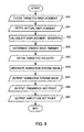
- the microprocessor 10 executes the control program represented by the flowchart of FIG. 8, and functions as the displacement deviation calculating means 106, the driving wave number determining means 105, the normative driving wave generating means 102, the targeted frequency setting means 103, and the targeted amplitude setting means 104.
- step S81 and step S82 are added, the program behavior will be explained focus on step S81 and step S82.
- the microprocessor 10 fetches the actual displacement Xa of the driven object 61 measured by the displacement measuring means 67 at step S81 after fetching the targeted displacement at step S41.
- step S43 The program behavior after step S43 is the same as that of FIG 3, and the explanation is omitted.
- the normative driving waves generated by the normative driving wave generating means 102 is supplied to the driving wave generating means 11, but the explanation of the driving wave generating means 11 is omitted because its behavior is the same as the controller according to the second invention.
- a forth embodiment of a control apparatus of an ultrasonic motor 4 includes a displacement deviation calculating means 106 for calculating a displacement deviation defined by a deviation between the targeted displacement of a driven object 61 driven by the ultrasonic motor 62 and the actual displacement of the driven object 61, a driving wave number determining means 105 for determining a driving wave number based on the displacement deviation calculated at the displacement deviation calculating means 106, a velocity deviation calculating means 107 for calculating a velocity deviation defined by a deviation between the targeted velocity of the driven object 61 and the actual velocity of the driven object 61, a normative driving wave generating means 102 for generating continuously normative driving waves in the number of times determined at the driving wave number determining means 105, inserted an interval determined based on the velocity deviation calculated at the velocity deviation calculating means 107, every at least one cycle of the normative driving waves, and a driving wave generating means 11 for generating driving waves having the predetermined frequency and the predetermined amplitude based
- the control apparatus is comprised of a microprocessor 10, which works as the displacement deviation calculating means 106, the driving wave number determining means 105, the normative driving wave generating means 102 and the velocity displacement calculating means 107, and the driving wave generating means 11 consist of discrete elements.
- the driving wave generating means 11 includes a frequency changing unit 111 and an amplitude changing unit 112.
- microprocessor 10 works as a frequency setting part 103 and an amplitude setting part 104.
- the hardware constitution of the microprocessor 10 is the same as the first embodiment of the ultrasonic motor, the explanation of the hardware constitution of the microprocessor 10 is omitted.
- the targeted displacement Xd is transferred from the targeted displacement setting part 65 consisting of a rotary encoder to the displacement deviation calculating means 106 in the microprocessor 10 through the interface 10d.
- An actual displacement measuring means 67 configured by a linear encoder to measure the actual displacement of the driven object 61 is attached to the driven object 61, and feedbacks the actual displacement Xa of the driven object 61 to the displacement deviation calculating means 106.
- the displacement deviation calculating means 106 calculates a displacement deviation defined by the deviation between the targeted displacement Xd and the actual displacement Xa.
- the targeted velocity Vd is transferred from the targeted velocity setting part 66 consisting of another rotary encoder to the velocity deviation calculating means 107 in the microprocessor 10 through the interface 10d.
- An actual velocity measuring means 68 to measure the actual velocity of the driven object 61 is attached to the driven object 61, and feedbacks the actual velocity Va of the driven object 61 to the velocity deviation calculating means 107.
- the actual velocity may be determined by differentiating the actual displacement measured by the actual displacement measuring means 67 with respect to time, or by using a known observer.
- the velocity deviation calculating means 107 calculates a velocity deviation Dv defined by the deviation between the targeted velocity Vd and the actual velocity Va supplied to the normative driving wave generating means 102.
- the normative driving wave generating means 102 is configured so as to determine the interval D as the function of the velocity deviation Dv .
- the interval D is calculated by compensating a normative interval Do with a compensating factor B which is a function of the velocity deviation Dv based on equation (9).
- D Do(1-B)T
- the compensating factor B is defined as an increasing function of the velocity deviation Dv as shown in FIG. 10.
- the normative driving wave generating means 102 is configured so as to generate the normative driving waves by inserting the interval D determined based on the equation (9), every at least one cycle of the normative driving waves.
- the microprocessor 10 executes the program shown by the flowchart of FIG. 11, and functions as the displacement deviation calculating means 106, the driving wave number determining means 105, the normative driving wave generating means 102, the velocity deviation calculating means 107, the targeted frequency setting means 103, and the targeted amplitude setting means 104.
- step S111 and step S112 are added, the program behavior will be explained focus on step S111 and step S112.
- step S41 has been explained referring the flowchart shown in FIG. 8, the explanation is omitted.
- the microprocessor 10 fetches the actual velocity Va of the driven object 61 measured by the actual velocity measuring means 68 at step S111 after fetching the targeted velocity Vd at step S43.
- the microprocessor 10 subtracts the actual velocity Va from the targeted velocity Vd to calculate the velocity deviation Dv at step S112, and determines the interval D based on equation (10) at step S44.
- D Do(1-B)T
- step S45 has been explained referring the flowchart shown in FIG 8, the explanation is omitted.
- the normative driving waves generated by the normative driving wave generating means 102 is supplied to the driving wave generating means 11, and the explanation of the driving wave generating means 11 is omitted because its behavior is the same as the controller according to the second invention.
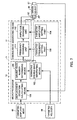
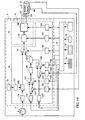
- a fifth embodiment of a control apparatus of an ultrasonic motor includes a driving pulse receiving part 121 to receive one or a plurality of driving pulses to energize an ultrasonic motor 16 which drives a driven object 61 every predetermined interval, a multiplier setting part 151 to set a multiplier, a manual-mode normative driving wave generating part 122 to generate continuously manual-mode normative driving waves, the numbers of which are equal to the numbers of driving pulses received at the driving pulse receiving part 121 multiplied by the multiplier set at the multiplier setting part 151.
- the fifth embodiment further includes a targeted displacement receiving part 123 to receive a targeted displacement of the driven object 61, a displacement deviation calculating part 124 to calculate a displacement deviation defined by a deviation between the targeted displacement received by the targeted displacement receiving part 123 and the actual displacement of the driven object 61, a displacement control signal choosing part 125 to choose between the targeted displacement received by the targeted displacement receiving part 123 and the displacement deviation calculated by the displacement deviation calculating part 124, as a displacement control signal, a driving wave number determining part 126 to determine a driving wave number based on the displacement control signal chosen by the displacement control signal choosing part 125.
- the fifth embodiment further includes a targeted velocity receiving part 127 to receive a targeted velocity of the driven object 61, a velocity deviation calculating part 128 to calculate a velocity deviation defined by a deviation between the targeted velocity received by the targeted velocity receiving part 127 and the actual velocity of the driven object 61, a velocity control signal choosing part 129 to choose between the targeted velocity received by said targeted velocity receiving part 127 and the velocity deviation calculated by the velocity deviation calculating part 128, as a velocity control signal, an auto-mode normative driving wave generating part 130 to generate continuously auto-mode normative driving waves in the number of times determined by the driving wave number determining part 126, inserted an interval determined based on the velocity control signal chosen by the velocity control signal choosing part 129, every at least one cycle of the auto-mode normative driving waves.
- the fifth embodiment further includes a normative driving wave choosing part 131 to choose normative driving waves between the manual-mode normative driving waves generated by the manual-mode normative driving wave generating part 122 and the auto-mode normative driving waves generated by the auto-mode normative driving wave generating part 139, and a driving wave generating part 14 to generate driving waves having the predetermined frequency and the predetermined amplitude based on the normative driving waves chosen by said normative driving wave choosing part.
- a normative driving wave choosing part 131 to choose normative driving waves between the manual-mode normative driving waves generated by the manual-mode normative driving wave generating part 122 and the auto-mode normative driving waves generated by the auto-mode normative driving wave generating part 139
- a driving wave generating part 14 to generate driving waves having the predetermined frequency and the predetermined amplitude based on the normative driving waves chosen by said normative driving wave choosing part.
- the control apparatus is comprised of a microprocessor 12, and the driving wave generating means 14 consists of discrete elements.
- the driving pulse receiving part 121 receives the driving pulses generated by the driving pulse generating part consisting of a rotary encoder to output the driving pulses to the manual-mode normative driving wave generating means 122.
- the manual-mode normative driving wave generating means 122 multiplies the number of the driving pulses by the multiplier set at the multiplier setting part 151 to output the product to one terminal of the normative driving wave choosing part 131.
- the targeted displacement receiving part 123 receives the targeted displacement generated by the targeted displacement generating part consisting of a rotary encoder, and outputs the targeted displacement to the displacement deviation calculating part 124 and one terminal of the displacement control signal choosing part 125.
- the displacement deviation calculating part 124 calculates the displacement deviation Dd defined by the deviation between the targeted displacement Xd and the actual displacement Xa fetched from the actual displacement receiving part 152 to output the displacement deviation Dd to another terminal of the displacement control mode choosing part 125.
- the displacement control signal choosing part 125 outputs the targeted displacement Xd or the displacement deviation Dd depending on the displacement control mode choosing signal received by the displacement control mode choosing signal receiving part 153.
- the driving wave number determining part 126 determines the driving wave number n as the function of the targeted displacement Xd based on equation (11), and outputs the driving wave number n to the auto-mode normative driving wave generating part 130.
- n f(Xd)
- the driving wave number determining part 126 determines the driving wave number n as the function of the displacement deviation Dd based on equation (12), and outputs the driving wave number n to the auto-mode normative driving wave generating part 130.
- n f(Dd)
- the targeted velocity receiving part 127 receives the targeted velocity generated by the targeted velocity generating part consisting of a rotary encoder, and outputs the targeted velocity to the velocity deviation calculating part 128 and one terminal of the velocity control signal choosing part 129.
- the velocity deviation calculating part 128 calculates the velocity deviation Dv defined by the deviation between the targeted velocity Vd and the actual velocity Va fetched from the actual velocity receiving part 154 to output the velocity deviation Dv to other terminal of the velocity control mode choosing part 129.
- the velocity control signal choosing part 129 outputs the targeted displacement Xd or the displacement deviation Dd depending on the displacement control mode choosing signal received by the displacement control signal choosing signal receiving part 155.
- the auto-mode normative driving wave generating part 130 When the velocity deviation control mode is selected, the auto-mode normative driving wave generating part 130 generates the auto-mode driving waves by inserting the interval D determined based on equation (14), which is a function of the velocity deviation Dv, every at least one cycle of the normative driving waves.
- D g(Dv)
- the normative driving wave generating part 130 is configured so as to generate the auto-mode normative driving waves by inserting the interval D, every at least one cycle of the normative driving waves in the number of times determined by the driving wave number determining part 126 to output the auto-mode normative driving wave to another terminal of the normative driving wave choosing part 131.
- the normative driving wave choosing part 131 outputs the manual-mode normative driving waves or the auto-mode normative driving waves to the driving wave generating part 14, depending to the manual-auto mode selecting signal received by the manual-auto mode selecting signal receiving part 156.
- the driving wave generating part 14 includes a frequency-changing unit 141 and an amplitude-changing unit 142.
- the frequency-changing unit 141 is configured so as to generate a first driving waves having the same phase as the normative driving waves selected at the normative driving wave choosing part 131, and a second driving waves having a phase difference in 90 degrees to the normative driving waves.
- the amplitude-changing unit 142 is configured so as to amplify the first driving waves and the second driving waves to supply them to the ultrasonic motor 62.
- the frequency of the amplified first and second driving waves can be modified by changing the targeted frequency set at the targeted frequency setting part 157.
- the amplitude of the amplified first and second driving waves can be modified by changing the targeted amplitude set at the targeted amplitude setting part 158.
- the first and second driving waves output from the power amplifying unit 142 are supplied to the piezoelectric element of the ultrasonic motor 62 at right angles each other. In result, the piezoelectric element moves elliptically, and drives the driven object 61 linearly.
- the microprocessor 12 executes the program shown in FIG. 13 to generate the normative driving waves.
- the microprocessor 10 fetches the normative driving wave choosing at step S131, and determines whether or not the auto-mode is selected at step S132.
- the microprocessor 10 fetches the targeted displacement Xd at step S41 and the displacement control-mode choosing signal at step 133, and determines whether or not the displacement feedback mode is selected at step S 134, when the microprocessor 12 determines that the auto-mode is chosen.
- the microprocessor 10 fetches the actual displacement of the driven object 61 at step S81, calculates the displacement deviation defined by the deviation between the targeted displacement and the actual displacement at step S82, and determines the driving wave number n based on the displacement deviation at step S42, when the microprocessor 12 determines that the displacement feedback mode is selected.
- the microprocessor 10 determines the driving wave number based on the targeted displacement at step S138, when the microprocessor determined that the displacement feedback mode is not chosen.
- the microprocessor 10 fetches the targeted velocity Vd at step S43, and the velocity control-mode choosing signal at step S135, and determines whether or not the velocity feedback mode is chosen at step S136.
- the microprocessor 10 fetches the actual velocity of the driven object 61 at step S111, calculates the velocity deviation defined as the deviation between the targeted velocity and the actual velocity at step S112, and generates the auto-mode normative driving waves in which the interval determined based on the velocity deviation is inserted every at least one cycle of the normative driving waves at step S137, when the microprocessor 12 determines that the velocity feedback mode is chosen.
- the microprocessor 10 generates the auto-mode normative driving waves in which the interval determined based on the targeted velocity is inserted every at least one cycle of the normative driving waves at step S139, when the microprocessor 12 determines that the velocity feedback mode is not chosen.
- the microprocessor 12 fetches the driving pulses at step S140, and the multiplier at step S141, when the microprocessor 12 determines that the manual mode is chosen.
- the microprocessor 12 multiplies the number of the driving pulses by the multiplier at step S142, and generates the manual-mode normative driving waves in the number of times equal to the product at step S 143.
- the microprocessor 12 outputs the auto-mode normative driving waves generated at step S137 or step S139, when the auto mode is selected.
- the microprocessor 12 outputs the manual-mode normative driving waves generated at step S 143, when the manual-mode is selected.
- microprocessor 12 outputs the targeted frequency at step S46, and the targeted amplitude at step S47.
- One ultrasonic motor driver can control a plurality of ultrasonic motors, when the driven object is moved with respect to a plurality of directions or axes.
- the ultrasonic motor driver applying the control apparatus of the ultrasonic motor according to the forth invention
- the control apparatus of the ultrasonic motor according to one of the first, the second, or the third invention may be applied to the ultrasonic motor driver.
- An ultrasonic motor controller includes not only the ultrasonic motor driver according to the fifth invention, but also a driving pulse generating part 71 such as a rotary encoder to generate driving pulses supplied to the driving pulse receiving part 121, a multiplier changing part to change the multiplier set at the multiple number setting part 151, an actual displacement measuring part to measure the actual displacement of the driven object 61, an actual velocity measuring part to measure the actual velocity of the driven object 61, and an operation controlling part 73 functioning as a targeted displacement generating part, a targeted velocity generating part, a displacement control-mode choosing signal outputting part, a velocity control-mode choosing signal outputting part, and a normative driving wave choosing signal outputting part.
- a driving pulse generating part 71 such as a rotary encoder to generate driving pulses supplied to the driving pulse receiving part 121
- a multiplier changing part to change the multiplier set at the multiple number setting part 151
- an actual displacement measuring part to measure the actual displacement of the driven object 61
- an actual velocity measuring part to measure
- a keyboard 74 To the operation controlling part 73, a keyboard 74, a display panel 75, a buzzer 76, and a communication interface 77 are connected.
- the operation controlling part 73 controls the ultrasonic motor driver based on the operation signals input from the keyboard 74, displays the operating status on the display panel 75, and activates the buzzer if required.
- the operation controlling part 73 can be connected to a personal computer and/or an instrument using RS-232C or GP-IP though the communication interface 77.
- the displacement of the driven object may be set by the personal computer, and the auto-manual mode, the displacement control mode and the velocity control mode may be changed by the personal computer.
- the ultrasonic motor controller includes an electric power equipment to generate a first electric power for driving the ultrasonic motor driver and a second electric power for supplying to the ultrasonic motor.
- the ultrasonic motor controller moves the driven object with respect to a specific one direction, but the ultrasonic motor controller may move the driven object with respect to a plurality of directions and/or axes.
- the X-axis displacement measured by the linear encoder 83 attached to the X-axis of the stage 8, and the Y-axis displacement measured by the linear encoder 84 attached to the Y-axis of the stage 8 are fed back to the ultrasonic motor controller 7. In this system, the velocity feedback is not applied.
- the ultrasonic motor controller 7 is connected to a personal computer 85 through RS-232C, and the personal computer 85 works as a maintenance tool and/or an operation tool.
- the ultrasonic motor controller 7 may be connected to measuring instruments not shown in FIG. 15, in order to monitor the operating status of the ultrasonic motor controller 7.
- the multiplier set in the multiplier setting part 151 is changed by the multiplier changing part 72, but the multiplier may be changed by the operation controlling part 73.
- the ultrasonic motor controller applying the ultrasonic motor driver according to the fifth embodiment
- the ultrasonic motor controller can be configured with the ultrasonic motor driver applying one of the first to the third embodiment.
Landscapes
- General Electrical Machinery Utilizing Piezoelectricity, Electrostriction Or Magnetostriction (AREA)
Applications Claiming Priority (4)
| Application Number | Priority Date | Filing Date | Title |
|---|---|---|---|
| JP2002366699 | 2002-12-18 | ||
| JP2002366699A JP2004201405A (ja) | 2002-12-18 | 2002-12-18 | 超音波モータにより駆動される可動体の速度及び変位制御方法及び装置 |
| JP2003004695 | 2003-01-10 | ||
| JP2003004695A JP2004222372A (ja) | 2003-01-10 | 2003-01-10 | 超音波モータドライバ及び超音波モータコントローラ |
Publications (2)
| Publication Number | Publication Date |
|---|---|
| EP1432111A2 true EP1432111A2 (de) | 2004-06-23 |
| EP1432111A3 EP1432111A3 (de) | 2006-04-12 |
Family
ID=32396331
Family Applications (1)
| Application Number | Title | Priority Date | Filing Date |
|---|---|---|---|
| EP03257767A Withdrawn EP1432111A3 (de) | 2002-12-18 | 2003-12-10 | Steuerungsverfahren und Vorrichtung für einen Ultraschallmotor sowie Ultraschallmotor-Steuerungsvorrichtung |
Country Status (2)
| Country | Link |
|---|---|
| US (3) | US7154209B2 (de) |
| EP (1) | EP1432111A3 (de) |
Families Citing this family (6)
| Publication number | Priority date | Publication date | Assignee | Title |
|---|---|---|---|---|
| EP1432111A3 (de) * | 2002-12-18 | 2006-04-12 | Hephaist Seiko Co., Ltd. | Steuerungsverfahren und Vorrichtung für einen Ultraschallmotor sowie Ultraschallmotor-Steuerungsvorrichtung |
| US7560869B2 (en) * | 2005-09-29 | 2009-07-14 | The Trustees Of Princeton University | Method and apparatus for remotely monitoring properties of gases and plasmas |
| JP2009153229A (ja) * | 2007-12-18 | 2009-07-09 | Sanyo Electric Co Ltd | ピエゾアクチュエータ制御回路及び防振制御回路 |
| FR2983742B1 (fr) * | 2011-12-09 | 2013-12-20 | Sinaptec | Dispositif electronique et systeme de commande d'applications mettant en oeuvre au moins un transducteur piezoelectrique, electrostrictif ou magnetostrictif |
| KR101686193B1 (ko) * | 2013-12-30 | 2016-12-15 | 주식회사 엠플러스 | 피에조 구동 장치 및 방법, 그를 이용한 피에조 |
| CN115556104B (zh) * | 2022-10-20 | 2023-06-09 | 北京精准医械科技有限公司 | 一种机器人单个关节位置的控制方法和系统及相关设备 |
Family Cites Families (16)
| Publication number | Priority date | Publication date | Assignee | Title |
|---|---|---|---|---|
| US6411008B1 (en) * | 1919-09-11 | 2002-06-25 | Canon Kabushiki Kaisha | Drive device for vibration type motor and image forming apparatus |
| JPH03220932A (ja) | 1990-01-26 | 1991-09-30 | Fujitsu Ltd | 主信号に制御情報を付加した伝送方式 |
| US5366504A (en) * | 1992-05-20 | 1994-11-22 | Boston Scientific Corporation | Tubular medical prosthesis |
| JPH05281370A (ja) * | 1992-03-31 | 1993-10-29 | Seiko Instr Inc | アナログ電子時計 |
| JP2757810B2 (ja) * | 1995-03-08 | 1998-05-25 | 日本電気株式会社 | 電源装置 |
| JPH09140168A (ja) * | 1995-11-15 | 1997-05-27 | Nikon Corp | 振動モータの駆動装置 |
| JP3347654B2 (ja) * | 1997-10-29 | 2002-11-20 | キヤノン株式会社 | 駆動装置 |
| JPH11150962A (ja) | 1997-11-13 | 1999-06-02 | Olympus Optical Co Ltd | 超音波モータの駆動回路 |
| JPH11191977A (ja) * | 1997-12-26 | 1999-07-13 | Asmo Co Ltd | モータの駆動回路 |
| US6476537B1 (en) * | 1999-11-03 | 2002-11-05 | New Focus, Inc. | Apparatus for controlling a piezoelectric assembly of a piezo actuator coupled with a driven member |
| JP2002060041A (ja) * | 2000-08-11 | 2002-02-26 | Ykk Corp | 圧電振動式パーツフィーダの制御方法と装置 |
| US6617758B2 (en) * | 2001-05-22 | 2003-09-09 | Texas Instruments Incorporated | Integrated charge and voltage mode drive circuit for piezo actuators used in mass data storage devices, or the like |
| JP2003284367A (ja) * | 2002-03-26 | 2003-10-03 | Seiko Instruments Inc | 超音波モータの制御システム |
| EP1432111A3 (de) * | 2002-12-18 | 2006-04-12 | Hephaist Seiko Co., Ltd. | Steuerungsverfahren und Vorrichtung für einen Ultraschallmotor sowie Ultraschallmotor-Steuerungsvorrichtung |
| US7037343B2 (en) * | 2002-12-23 | 2006-05-02 | Python, Inc. | Stomach prosthesis |
| JP4358544B2 (ja) * | 2003-04-08 | 2009-11-04 | オリンパス株式会社 | 超音波アクチュエータ駆動装置及び超音波アクチュエータ駆動方法 |
-
2003
- 2003-12-10 EP EP03257767A patent/EP1432111A3/de not_active Withdrawn
- 2003-12-16 US US10/737,632 patent/US7154209B2/en not_active Expired - Fee Related
-
2006
- 2006-05-04 US US11/418,039 patent/US20070001546A1/en not_active Abandoned
- 2006-05-04 US US11/417,989 patent/US20060197410A1/en not_active Abandoned
Also Published As
| Publication number | Publication date |
|---|---|
| US20060197410A1 (en) | 2006-09-07 |
| US20070001546A1 (en) | 2007-01-04 |
| US20040164646A1 (en) | 2004-08-26 |
| EP1432111A3 (de) | 2006-04-12 |
| US7154209B2 (en) | 2006-12-26 |
Similar Documents
| Publication | Publication Date | Title |
|---|---|---|
| JP5650052B2 (ja) | 振動試験装置及びその制御方法 | |
| US8450905B2 (en) | Methods for controlling velocity of at least partially resonant actuators systems and systems thereof | |
| Do et al. | A new approach of friction model for tendon-sheath actuated surgical systems: Nonlinear modelling and parameter identification | |
| DE102013113689B4 (de) | Dichte-Meßgerät | |
| US7590502B2 (en) | Testing apparatus for steering apparatus | |
| JP6129409B2 (ja) | 入出力装置、ステアリング測定装置、および、制御装置 | |
| US7085484B2 (en) | Driving device, position controller provided with driving device, and camera provided with position controller | |
| US7154209B2 (en) | Control method and apparatus of an ultrasonic motor, and an ultrasonic motor driver and controller | |
| CN111174995B (zh) | 机床以及振动诊断辅助方法 | |
| US11077552B2 (en) | Control system, machine learning apparatus, maintenance assistance apparatus, data generating method, and maintenance assisting method | |
| US5396804A (en) | Apparatus and method for force-controlled fatigue testing | |
| JP6988989B2 (ja) | 異常検出装置及び異常検出方法 | |
| Barsomian et al. | Dynamic characterization and control of a back-support exoskeleton 3D-printed cycloidal actuator | |
| EP2130008A1 (de) | Vibrationsdosimeter zur ermittlung der vibrationsbelastung | |
| CN109195750A (zh) | 通过脉冲式紧固估算夹紧力 | |
| JP2009081923A (ja) | モータ制御システムとそのパラメータ調整方法 | |
| JP2004222372A (ja) | 超音波モータドライバ及び超音波モータコントローラ | |
| Pacas et al. | Identification of the mechanical system of a drive in the frequency domain | |
| JP4210921B2 (ja) | サーボ制御装置の指令作成方法および装置 | |
| Mangeot | Operation of a quasi-static piezomotor in transitory frequency range up to resonance | |
| KR20010107996A (ko) | 제어장치 | |
| US10481598B2 (en) | Motion system with sensor outputs and haptic controls | |
| JP2000141262A (ja) | ロボット制御装置 | |
| KR100854557B1 (ko) | 직류 모터 시뮬레이션 시스템 및 방법. | |
| KR100391452B1 (ko) | 서보 드라이브/모터 시뮬레이터 |
Legal Events
| Date | Code | Title | Description |
|---|---|---|---|
| PUAI | Public reference made under article 153(3) epc to a published international application that has entered the european phase |
Free format text: ORIGINAL CODE: 0009012 |
|
| AK | Designated contracting states |
Kind code of ref document: A2 Designated state(s): AT BE BG CH CY CZ DE DK EE ES FI FR GB GR HU IE IT LI LU MC NL PT RO SE SI SK TR |
|
| AX | Request for extension of the european patent |
Extension state: AL LT LV MK |
|
| PUAL | Search report despatched |
Free format text: ORIGINAL CODE: 0009013 |
|
| AK | Designated contracting states |
Kind code of ref document: A3 Designated state(s): AT BE BG CH CY CZ DE DK EE ES FI FR GB GR HU IE IT LI LU MC NL PT RO SE SI SK TR |
|
| AX | Request for extension of the european patent |
Extension state: AL LT LV MK |
|
| 17P | Request for examination filed |
Effective date: 20060518 |
|
| 17Q | First examination report despatched |
Effective date: 20060628 |
|
| AKX | Designation fees paid |
Designated state(s): CH DE FR GB IT LI |
|
| STAA | Information on the status of an ep patent application or granted ep patent |
Free format text: STATUS: THE APPLICATION IS DEEMED TO BE WITHDRAWN |
|
| 18D | Application deemed to be withdrawn |
Effective date: 20061109 |