EP1434037B1 - Distributeur de fluide et tubes distributeurs associés - Google Patents
Distributeur de fluide et tubes distributeurs associés Download PDFInfo
- Publication number
- EP1434037B1 EP1434037B1 EP04008332A EP04008332A EP1434037B1 EP 1434037 B1 EP1434037 B1 EP 1434037B1 EP 04008332 A EP04008332 A EP 04008332A EP 04008332 A EP04008332 A EP 04008332A EP 1434037 B1 EP1434037 B1 EP 1434037B1
- Authority
- EP
- European Patent Office
- Prior art keywords
- valve block
- discharge tube
- valve
- channel
- liquid
- Prior art date
- Legal status (The legal status is an assumption and is not a legal conclusion. Google has not performed a legal analysis and makes no representation as to the accuracy of the status listed.)
- Expired - Lifetime
Links
Images


Classifications
-
- B—PERFORMING OPERATIONS; TRANSPORTING
- B05—SPRAYING OR ATOMISING IN GENERAL; APPLYING FLUENT MATERIALS TO SURFACES, IN GENERAL
- B05B—SPRAYING APPARATUS; ATOMISING APPARATUS; NOZZLES
- B05B11/00—Single-unit hand-held apparatus in which flow of contents is produced by the muscular force of the operator at the moment of use
- B05B11/01—Single-unit hand-held apparatus in which flow of contents is produced by the muscular force of the operator at the moment of use characterised by the means producing the flow
- B05B11/10—Pump arrangements for transferring the contents from the container to a pump chamber by a sucking effect and forcing the contents out through the dispensing nozzle
- B05B11/1001—Piston pumps
- B05B11/1015—Piston pumps actuated without substantial movement of the nozzle in the direction of the pressure stroke
-
- B—PERFORMING OPERATIONS; TRANSPORTING
- B05—SPRAYING OR ATOMISING IN GENERAL; APPLYING FLUENT MATERIALS TO SURFACES, IN GENERAL
- B05B—SPRAYING APPARATUS; ATOMISING APPARATUS; NOZZLES
- B05B11/00—Single-unit hand-held apparatus in which flow of contents is produced by the muscular force of the operator at the moment of use
- B05B11/0005—Components or details
-
- B—PERFORMING OPERATIONS; TRANSPORTING
- B05—SPRAYING OR ATOMISING IN GENERAL; APPLYING FLUENT MATERIALS TO SURFACES, IN GENERAL
- B05B—SPRAYING APPARATUS; ATOMISING APPARATUS; NOZZLES
- B05B1/00—Nozzles, spray heads or other outlets, with or without auxiliary devices such as valves, heating means
- B05B1/30—Nozzles, spray heads or other outlets, with or without auxiliary devices such as valves, heating means designed to control volume of flow, e.g. with adjustable passages
- B05B1/3093—Recirculation valves, i.e. the valve element opens a passage to the nozzle and simultaneously closes at least partially a return passage the feeding means
-
- B—PERFORMING OPERATIONS; TRANSPORTING
- B05—SPRAYING OR ATOMISING IN GENERAL; APPLYING FLUENT MATERIALS TO SURFACES, IN GENERAL
- B05B—SPRAYING APPARATUS; ATOMISING APPARATUS; NOZZLES
- B05B11/00—Single-unit hand-held apparatus in which flow of contents is produced by the muscular force of the operator at the moment of use
- B05B11/01—Single-unit hand-held apparatus in which flow of contents is produced by the muscular force of the operator at the moment of use characterised by the means producing the flow
- B05B11/10—Pump arrangements for transferring the contents from the container to a pump chamber by a sucking effect and forcing the contents out through the dispensing nozzle
- B05B11/1001—Piston pumps
- B05B11/1005—Piston pumps with means for adjusting or modifying pump stroke
- B05B11/1007—Piston pumps with means for adjusting or modifying pump stroke by adjusting or modifying the pump end-of-sucking-stroke position
-
- B—PERFORMING OPERATIONS; TRANSPORTING
- B05—SPRAYING OR ATOMISING IN GENERAL; APPLYING FLUENT MATERIALS TO SURFACES, IN GENERAL
- B05B—SPRAYING APPARATUS; ATOMISING APPARATUS; NOZZLES
- B05B15/00—Details of spraying plant or spraying apparatus not otherwise provided for; Accessories
- B05B15/50—Arrangements for cleaning; Arrangements for preventing deposits, drying-out or blockage; Arrangements for detecting improper discharge caused by the presence of foreign matter
-
- G—PHYSICS
- G01—MEASURING; TESTING
- G01F—MEASURING VOLUME, VOLUME FLOW, MASS FLOW OR LIQUID LEVEL; METERING BY VOLUME
- G01F11/00—Apparatus requiring external operation adapted at each repeated and identical operation to measure and separate a predetermined volume of fluid or fluent solid material from a supply or container, without regard to weight, and to deliver it
- G01F11/02—Apparatus requiring external operation adapted at each repeated and identical operation to measure and separate a predetermined volume of fluid or fluent solid material from a supply or container, without regard to weight, and to deliver it with measuring chambers which expand or contract during measurement
- G01F11/021—Apparatus requiring external operation adapted at each repeated and identical operation to measure and separate a predetermined volume of fluid or fluent solid material from a supply or container, without regard to weight, and to deliver it with measuring chambers which expand or contract during measurement of the piston type
- G01F11/025—Apparatus requiring external operation adapted at each repeated and identical operation to measure and separate a predetermined volume of fluid or fluent solid material from a supply or container, without regard to weight, and to deliver it with measuring chambers which expand or contract during measurement of the piston type with manually operated pistons
- G01F11/028—Apparatus requiring external operation adapted at each repeated and identical operation to measure and separate a predetermined volume of fluid or fluent solid material from a supply or container, without regard to weight, and to deliver it with measuring chambers which expand or contract during measurement of the piston type with manually operated pistons the dosing device being provided with a dip tube and fitted to a container, e.g. to a bottleneck
-
- G—PHYSICS
- G01—MEASURING; TESTING
- G01F—MEASURING VOLUME, VOLUME FLOW, MASS FLOW OR LIQUID LEVEL; METERING BY VOLUME
- G01F15/00—Details of, or accessories for, apparatus of groups G01F1/00 - G01F13/00 insofar as such details or appliances are not adapted to particular types of such apparatus
- G01F15/12—Cleaning arrangements; Filters
Definitions
- the invention relates to a device for dispensing a liquid with the features of the preamble of claim 1 and an output cannula for such a device.
- the known device for dispensing a liquid, from which the invention proceeds ( WO 97/49974 ), has an output cannula attached to the valve block of the conveyor and in which the outflow line is formed.
- the dispensing cannula is made in one piece and designed arcuate, so that the liquid in the outflow first flows horizontally away from the valve block and is then deflected vertically downwards by the arcuate guide the outflow line.
- the teaching is based on the problem to improve the aforementioned device for dispensing a liquid, from which the invention proceeds, in terms of the design of the dispensing area.
- the dispensing cannula is provided at its end facing away from the valve block with a spout element which can be brought into a dispensing position relative to the dispensing cannula, in which the liquid emerging from the outflow line is deflected vertically downwards.
- the return line can be connected to the outflow line, so that the outflow line can also be completely rinsed in the context of a rinsing process which possibly comprises a plurality of pump strokes.
- the discharge line and the return line are formed together in the preferably made of a plastic material, or in a particularly high-quality embodiment made of stainless steel dispensing cannula.
- a configuration of the dispensing cannula proves to be particularly advantageous, especially with regard to production-related aspects with regard to simple assembly, and also enables effective stiffening of the dispensing cannula.
- the outflow line and the return line are preferably of equal length and advantageously each have the same channel cross section.
- the two lines advantageously each have a circular cross-section and, in the case of a sprayed Ausshingningsform in the longitudinal direction each tapers slightly tapered.
- particularly high surface qualities can be achieved with regard to the line inner walls delimiting the two lines.
- the ejection cannula is advantageously of cylindrical or prismatic shape.
- the outflow line and the return line are advantageously designed such that the outlet opening of the outflow line of an inlet opening of the return line is arranged directly adjacent in an outlet region of the dispensing cannula.
- an immediate bridging of the two lines is possible by means of a flushing connection formed in the connecting device.
- the outflow line and the return line are designed such that their longitudinal axes are parallel to each other.
- the dispensing cannula is advantageously designed in such a way that it has a circular, elliptical or preferably "8" -shaped cross-section in a sectional plane perpendicular to the longitudinal axis of the outflow line.
- the spout element is advantageously provided with a handle device for manual switching between a bridging position, a dispensing position and possibly also a closed position in which the outlet opening of the dispensing cannula is closed.
- Said gripping device is advantageously formed integrally with the spout element formed from a plastic material, for example.
- the spout is pivotally mounted or slidably mounted on the dispensing cannula.
- the pivoting or displacement axis in this case runs essentially in the longitudinal direction of the dispensing cannula.
- the spout element is designed in an advantageous manner closure cap-like and mounted on an outer peripheral surface of the dispensing cannula pivotable or displaceable.
- the dispensing cannula is connected to a valve block in which a fluid supply channel and a fluid return channel are formed, which are respectively connected to the outflow line and the return line.
- This valve block is advantageously made of a plastic material by injection molding or machining.
- the fluid supply channel formed in the valve block and the fluid return channel also formed in the valve block can be formed on production technology particularly advantageous manner by cylindrical core elements formed in the formation of the valve block in a mold Penetrate molding space and can be removed after curing of the plastic material from this.
- the dispensing cannula is preferably formed as a separate component and pressed into the valve block only during an assembly step. This makes it possible on the one hand in an advantageous manner to combine different dispensing cannulas and possibly also different valve blocks as needed with each other.
- the use of a press-connection device allows a particularly firmly adhering, high-density attachment of the dispensing cannula to the valve block.
- the dispensing cannula may also be attached to the valve block via threaded means.
- the dispensing cannula or a union nut is preferably provided with a threaded portion.
- the valve block may also be formed from a block material, for example by machining.
- a block material for example by machining.
- PP polypropylene
- PE polyethylene
- polyamide material preferably made of a Teflon, polypropylene (PP), polyethylene (PE) or polyamide material.
- a particularly stable embodiment of the device which is highly dense in the region of the metering cylinder base is provided in that the conveying or metering cylinder is formed integrally with the valve block.
- the delivery or metering cylinder and the valve block and possibly also the output cannula can be formed within a single plastic injection process inside a corresponding mold, so that after opening the mold a consisting at least of conveying or metering cylinder and valve block assembly the mold can be removed.
- the mold is advantageously formed in two parts at least, wherein a separating surface extending between the two mold parts preferably extends substantially parallel to a plane which contains a central axis of the conveying or metering cylinder.
- the conveying or metering cylinder comprises a cylinder insert formed from a glass, ceramic, thermoplastic or thermosetting plastic material, in a received integrally with the valve block formed shell portion, in particular injected.
- This advantageously makes it possible to ensure an extremely high sealing effect between the inner wall of the conveying or metering cylinder and a conveying or metering piston which can be moved back and forth smoothly therein. Due to the preferably integrally formed with the valve block shell portion is given for the cylinder insert effective reinforcement and an effective splinter protection.
- valve block is formed as a skeleton construction with spaced ridges these spaced apart webs extend in an advantageous manner substantially parallel to a central axis of the conveying or dosing.
- the individual webs can be stiffened for further stiffening of the valve block by further, truss-like arranged cross connecting webs.
- a receiving recess for receiving a foot portion of the dispensing cannula is arranged in such an advantageous manner that it passes through one of the axially extending webs radially.
- a central axis of the preferably cylindrical receiving recess extends in an advantageous manner in a corresponding median plane of the axially extending stiffening web.
- the receiving recess is received in an advantageous manner in a pot-like wall section.
- This pot-like wall section can be further stiffened by further, for example radial Querversteifungsstege even further.
- a positioning device is advantageously formed by corresponding sections of the valve block and the dispensing cannula, by means of which the fastening position of the dispensing cannula to the valve block is clearly established.
- this positioning device can either have a cannula-side engagement section which can be brought into engagement with an engagement counterpart section formed on the valve block side, or an engagement section formed on the valve block in the region of the receiving recess, which can be brought into engagement with a cannula-side engagement counterpart section.
- a plurality of sealing lamellae are preferably formed on a mounting portion of the dispensing cannula, which contact under high surface pressure with a corresponding inner peripheral portion of a receiving recess formed in the valve block.
- the invention also provides a dispensing cannula for such a liquid dispenser according to the invention, as mentioned in claim 22.
- advantageous embodiments and developments are the subject of the subsequent sub-claims.
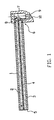
- dispensing cannula comprises a base body 1, which is preferably made of a plastic material.
- a base body 1 which is preferably made of a plastic material.
- both an outflow 2 and a return line 3 are formed.
- the outflow line 2 and the return line 3 are separated from one another by a partition wall section 4, which is formed integrally with the base body 1.
- Both the outflow line 2 and the return line 3 have a circular cross-section and open in the embodiment shown here in a plane-shaped end face. 5
- the dispensing cannula On a side facing away from the end face 5 of the base body 1, the dispensing cannula is provided with a mounting portion 6, via which the dispensing cannula is attachable to a here designated by the reference numeral 7 valve block.
- the mounting portion 6 comprises in the embodiment shown here a substantially cylindrical Einpreßzapfenabites 8, which is pressed in close fit, sealingly into a correspondingly formed fitting bore of the valve block 7.
- the threaded device is advantageously designed such that in the tightened state no cavity remains between the thread flanks. This can be achieved in particular by a slightly conical thread.
- a fluid supply channel 9 and a fluid return channel 10 are formed.
- the fluid supply channel 9 comprises a suction valve, not shown here, and opens into the outflow line 2 via an end opening formed in the attachment section 6.
- the return line 3 formed in the base body 1 communicates with the through-hole boring radially through the fastening or press-in pin section 8 or threaded pin section the fluid return passage 10 in connection.
- the fluid return passage 10 is formed here as a substantially rectilinear channel and extends slightly inclined from a lower portion of the valve block 7 to the mounting portion 8.
- the high surface pressure between the mounting portion 8 and the inner wall of the formed in the valve block 7 mounting hole is a high density the transition region between the return line 3 and formed in the valve block 7 fluid return passage 10 is reached.
- the discharge line 2 and the return line 3 are formed in a side-by-side manner. It is also possible to design the discharge line 2 and the return line 3 coaxially with one another, so that one of the two lines is formed by a correspondingly dimensioned annular space.
- the return line 3 extends continuously uninterrupted from the outlet opening of the discharge line 2 back to the valve block. 7
- a complete flushing of the outflow line 2 can be achieved, for example, by placing a cap element on the base body 1 in the region of the end face 5, which establishes a connection between the outflow line 2 and the return line 3.
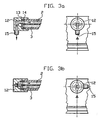
- a spout element 12 may be used, as described below in connection with FIGS 2a and 2 B is described.
- Deviating from the illustration according to Fig.1 is provided for receiving the dispensing cannula valve block 7 with a designated by the reference numeral 11 (only partially shown) conveying or metering cylinder shown here completely.
- the dispensing cannula shown here is attached to the valve block 7 in the same way as previously in connection with Fig.1 was explained.
- the dispensing cannula is provided with a spout element 12, which is attached pivotably or displaceably to the base body 1. In the position shown here, the spout is in a dispensing position and allows the outflow of a first by the delivery or metering cylinder via a suction, not shown suction fluid through the fluid supply channel 9 and the Ausström strig 2.
- two sliding discs 13, 14 are provided, which via the spout 12 and an engagement structure not shown here between the spout element 12 and the base body 1 in close contact with the in Fig.1 are held by the reference numeral 5 designated end face.
- the sliding discs 13, 14 are preferably formed of a glass, plastic or ceramic material and provided with through holes, which can be brought into line depending on the position of the spout 12.
- the spout element 12 is pivotable about a pivot axis extending parallel to the central axis of the main body 1 of the dispensing cannula.
- a short deflection bore 15 or deflection channel is formed, via which the fluid emerging from the discharge line 2 is deflected.
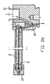
- the representation according to Figure 4 shows an axial sectional view through a Dosierdispenser with an integrally formed with the valve block 7 conveying or metering cylinder 11, wherein the delivery or metering cylinder 11 is accommodated in a formed integrally with the valve block 7 shell portion 16.
- the delivery or metering piston is designed as a precision ground piston and delimits a delivery or metering chamber 19 which can be varied in volume in the delivery or metering cylinder 11.
- the allowable stroke of the delivery or delivery Metering piston 18 and thus the maximum volume of the delivery or metering 19 are set.
- the adjusting device 20 acts together with a stop 21 which is formed integrally with the shell portion 16.
- the stop 21 surrounds an upper end region of the delivery or metering cylinder 11 and also forms a reinforcing member for reinforcing the upper opening of the conveying or metering cylinder eleventh
- a container valve 22 which in the embodiment shown here comprises a valve ball 23 which rests on a precision valve seat 24, which is formed in the embodiment shown here by a precision-formed surface portion of the valve body 7.
- a suction channel 26 formed in a hose pin 25 extends below the container valve 22, a suction channel 26 formed in a hose pin 25 extends.
- the opening stroke of the valve ball 23 is limited by a sleeve member 27, which is pressed into the valve block 7 through the conveying or metering cylinder 11.
- the bushing element 27 forms a fluid passageway 28, which connects the intake channel 26 via the container valve 22 with the conveying or metering chamber 19.
- the bush element 27 is provided with a radial passage opening 29, which connects the fluid passageway 28 with a valve 30 accommodated in the base body 1 of the dispensing cannula.
- the valve 30 accommodated in the base body 1 comprises a valve ball 32 urged into a closed position by means of a spring 31 and a valve seat element 33 pressed into the main body 1 of the dispensing cannula, which in the embodiment shown here is formed from a plastic, glass or ceramic material ,
- Said valve spring 31 is seated in the outflow conduit 2 formed in the dispensing cannula, which extends continuously from the valve 30 to its outlet opening.
- the outlet opening of the outflow line 2 is arranged immediately adjacent to the inlet opening of the return line 3.
- the return line 3 extending in the dispensing cannula has essentially the same length as the outflow line 2 formed in the dispensing cannula.
- the dispensing cannula is pressed into the valve block 7 via the press-in spigot section 8.
- the Einpreßzapfenabites 8 is provided with a radial through-hole, which is connected to a formed in the valve block fluid path means, via which any fluid conveyed back through the return line can get back into the container.
- the valve block 7 is designed here as a skeleton construction and attachable by means of a union nut 34 to a container or, for example, to a supply base of an automatically operated metering device.
- a union nut 34 to a container or, for example, to a supply base of an automatically operated metering device.
- the valve block 7 and the sheath section 16 to be made in one piece, ie. form as an integral part.
- a corresponding integral embodiment advantageously eliminates the valve seat member 33, and a corresponding valve seat surface is formed by a peripheral wall of, the sleeve member 27 radially passing through hole.
- valve ball 32 and possibly also the valve spring 31 can either be inserted into the valve block 7 before the female element 27 is pressed in or, alternatively, can be introduced through the discharge line 2 into the valve block 7.
- the discharge line 2 and the return line 3 are formed coaxially with each other, wherein preferably the outflow line 2 surrounds the return line 3.
- the invention is not limited to the embodiments described above.
- the dispensing cannula in a curved manner, so that the outlet opening located in the outlet area of the outflow line points downwards in the use position of a corresponding device. It is also possible to close the dispensing cannula in the region of its end face 5 and to carry out a fluid discharge, in particular with respect to the outflow line, by means of a radial bore passing through the peripheral wall of the dispensing cannula.
- the outer fluid path means the discharge line.
- valve in particular a ball valve, which prevents fluid leakage, for example, due to a pressure change in the container.
- This valve is advantageously arranged in the region of the inlet mouth of the return line or in the valve block.
- the spout element is advantageously designed such that it can be brought into a non-use position, in which the two lines formed in the dispensing cannula are shut off towards the outside.
Landscapes
- Physics & Mathematics (AREA)
- Fluid Mechanics (AREA)
- General Physics & Mathematics (AREA)
- Containers And Packaging Bodies Having A Special Means To Remove Contents (AREA)
- Infusion, Injection, And Reservoir Apparatuses (AREA)
- Sampling And Sample Adjustment (AREA)
- Coating Apparatus (AREA)
- Feeding, Discharge, Calcimining, Fusing, And Gas-Generation Devices (AREA)
- Injection Moulding Of Plastics Or The Like (AREA)
- Processing And Handling Of Plastics And Other Materials For Molding In General (AREA)
- Reciprocating Pumps (AREA)
Claims (30)
- Dispositif pour distribuer un liquide comprenant un système de transport avec un cylindre de transport ou de dosage (11),
avec un piston de transport ou de dosage (18) déplaçable de manière alternative dans le cylindre de transport ou de dosage (11), qui limite dans le cylindre de transport ou de dosage (11) un espace de transport ou de dosage (19) de volume variable, pour transporter ou doser le liquide provenant d'un récipient dans une conduite d'écoulement (2),
avec une ouverture d'écoulement au niveau de laquelle le liquide transporté s'écoule hors de la conduite d'écoulement (2),
avec une conduite de retour (3) pour ramener le liquide dans le récipient,
avec un système d'ajustement (20) pour l'ajustement de la course du piston de transport ou de dosage (18),
avec un bloc de soupape (7) auquel est connecté le cylindre de transport ou de dosage (11), et qui est accouplé d'une part à une soupape du récipient (22) pour aspirer du liquide dans le cylindre de transport ou de dosage (11) et d'autre part à une soupape (30) pour transporter du liquide hors du cylindre de transport ou de dosage (11) dans la conduite d'écoulement (2), et
avec un tube d'évacuation qui est monté sur le bloc de soupape (7) et qui est réalisé dans la conduite d'écoulement (2),
caractérisé en ce que
le tube d'évacuation est pourvu sur son extrémité opposée au bloc de soupape (7) d'un élément verseur (12) qui est monté de manière pivotante ou coulissante sur un corps de base (1), contenant la conduite d'écoulement (2), du tube d'évacuation,
en ce que dans l'élément verseur (12) est réalisé un canal de déviation court (15),
en ce que dans une position de distribution de l'élément verseur (12), le canal de déviation (15) dévie verticalement vers le bas le liquide sortant de la conduite d'écoulement (2) et
en ce que dans une position de contournement de l'élément verseur (12), la conduite d'écoulement (2) est connectée à la conduite de retour (3). - Dispositif selon la revendication 1, caractérisé en ce que la conduite de retour (3) s'étend le long de la conduite d'écoulement (2) et est réalisée de préférence dans le tube d'évacuation à côté de la conduite d'écoulement (2), notamment est formée intégralement dans le tube d'évacuation.
- Dispositif selon la revendication 1 ou 2, caractérisé en ce que la conduite d'écoulement (2) et la conduite de retour (3) sont réalisées coaxialement dans le tube d'évacuation.
- Dispositif selon l'une quelconque des revendications 1 à 3, caractérisé en ce que l'élément verseur (12) formant le canal de déviation (15) est enfiché sur le corps de base (1) du tube d'évacuation.
- Dispositif selon l'une quelconque des revendications 1 à 4, caractérisé en ce que le bloc de soupape (7) peut être connecté au récipient par le biais d'un écrou d'accouplement (34).
- Dispositif selon l'une quelconque des revendications 1 à 5, caractérisé en ce que la conduite d'écoulement (2) et la conduite de retour (3) sont réalisées essentiellement avec la même longueur.
- Dispositif selon l'une quelconque des revendications 1 à 6, caractérisé en ce que l'ouverture de sortie de la conduite d'écoulement (2) est disposée à côté d'une ouverture d'entrée de la conduite de retour (3).
- Dispositif selon l'une quelconque des revendications 1 à 7, caractérisé en ce que l'élément verseur (12) est pourvu d'un système de préhension (17) pour commuter manuellement entre la position de contournement et la position de distribution.
- Dispositif selon la revendication 8, caractérisé en ce que l'élément verseur (12) peut être commuté dans une position de fermeture dans laquelle le tube d'évacuation est bloqué vers l'extérieur.
- Dispositif selon l'une quelconque des revendications 1 à 9, caractérisé en ce que l'élément verseur (12) peut être déplacé de manière pivotante autour d'un axe de pivotement qui s'étend essentiellement dans la direction longitudinale du tube d'évacuation.
- Dispositif selon l'une quelconque des revendications 1 à 10, caractérisé en ce que dans le bloc de soupape (7) sont réalisés un canal d'alimentation en liquide (9) et un canal de retour de liquide (10), qui sont connectés de manière correspondante à la conduite d'écoulement (2) et à la conduite de retour (3).
- Dispositif selon l'une quelconque des revendications 1 à 11, caractérisé en ce que dans la course de liquide ramenant dans le récipient est disposée une soupape, notamment une soupape sphérique.
- Dispositif selon l'une quelconque des revendications 1 à 12, caractérisé en ce que le tube d'évacuation est pressé dans le bloc de soupape (7).
- Dispositif selon l'une quelconque des revendications 1 à 13, caractérisé en ce que le cylindre de transport ou de dosage (11) est réalisé d'une seule pièce avec le bloc de soupape (7).
- Dispositif selon la revendication 14, caractérisé en ce que le cylindre de transport ou de dosage (11) comprend un insert cylindrique formé en un matériau en verre, en céramique, ou en plastique thermoplastique ou duroplastique, qui est reçu, notamment par injection, dans une portion d'enveloppe (16) réalisée d'une seule pièce avec le bloc de soupape (7).
- Dispositif selon l'une quelconque des revendications 1 à 13, caractérisé en ce que le cylindre de transport ou de dosage (11) est vissé dans le bloc de soupape (7).
- Dispositif selon l'une quelconque des revendications 1 à 16, caractérisé en ce que le bloc de soupape (7) est réalisé sous forme de construction squelette avec des nervures espacées.
- Dispositif selon la revendication 17, caractérisé en ce que le bloc de soupape (7) est pourvu d'un évidement de réception pour recevoir une portion de base du tube d'évacuation, l'évidement de réception étant réalisé sur le bloc de soupape (7) de telle sorte qu'il traverse radialement une nervure s'étendant dans un plan axial.
- Dispositif selon l'une quelconque des revendications 1 à 18, caractérisé en ce que l'on prévoit un système de positionnement de tube d'évacuation, pour fixer la position du tube d'évacuation sur le bloc de soupape (7).
- Dispositif selon la revendication 19, caractérisé en ce que le système de positionnement de tube d'évacuation présente une portion d'engagement (8) réalisée du côté du tube, qui peut être amenée en prise avec une portion d'engagement conjuguée réalisée du côté du bloc de soupape.
- Dispositif selon la revendication 18, caractérisé en ce qu'une portion d'engagement est réalisée sur le bloc de soupape (7) dans la région de l'évidement de réception, laquelle peut être amenée en prise avec une portion d'engagement conjuguée du tube d'évacuation.
- Tube d'évacuation pour un distributeur doseur de liquide selon l'une quelconque des revendications 1 à 21, comprenant un premier système de canal (2) pour distribuer un liquide par le biais d'une ouverture de sortie et un deuxième système de canal (3) qui s'étend le long du premier système de canal (2), les systèmes de canaux (2, 3) étant prévus dans le tube d'évacuation et les deux systèmes de canaux (2, 3) pouvant être connectés pour le transfert d'un liquide transporté par le premier système de canal (2) dans le deuxième système de canal (3) dans la région de l'ouverture de sortie,
caractérisé en ce que
dans la région de l'ouverture de sortie du premier système de canal (2), un élément verseur (12) est prévu, lequel est monté de manière pivotante ou coulissante sur un corps de base (1), contenant la conduite d'écoulement (2), du tube d'évacuation,
en ce que dans l'élément verseur (12) est réalisé un canal de déviation court (15),
en ce que dans une position de distribution de l'élément verseur (12), le canal de déviation (15) dévie le liquide sortant de la conduite d'écoulement (2) et
en ce que l'élément verseur (12) peut être amené dans une position de contournement, dans laquelle le liquide s'écoulant hors de l'ouverture de sortie du premier système de canal (2) peut être ramené dans le deuxième système de canal (3). - Tube d'évacuation selon la revendication 22, caractérisé en ce que le tube d'évacuation présente un corps de base allongé (1) sur une extrémité duquel est réalisée l'ouverture de sortie.
- Tube d'évacuation selon la revendication 23, caractérisé en ce que le corps de base (1) présente une surface frontale plane (5) et en ce que l'élément verseur (12) est posé sur la surface frontale plane (5), et de préférence, des canaux sont réalisés dans la surface frontale (5) du corps de base (1) et dans une surface frontale de l'élément verseur (12).
- Tube d'évacuation selon la revendication 24, caractérisé en ce qu'au moins une rondelle de glissement (13, 14) est prévue entre l'élément verseur (12) et la surface frontale plane (5), la rondelle de glissement (13, 14) présentant une ouverture de passage qui forme de manière sélective une connexion fluidique entre l'ouverture de sortie de la conduite d'écoulement (2) et la conduite de retour (3).
- Tube d'évacuation selon l'une quelconque des revendications 23 à 25, caractérisé en ce que
le premier et le deuxième système de canal (2, 3) sont réalisés parallèlement l'un à l'autre et notamment sont formés intégralement dans le corps de base (1), notamment la paroi définissant à chaque fois le premier et le deuxième système de canal est formée par le corps de base (1). - Tube d'évacuation selon l'une quelconque des revendications 23 à 26, caractérisé en ce que
le corps de base (1) présente sur son extrémité opposée à l'ouverture de sortie une portion de connexion (6) par le biais de laquelle le corps de base (1) peut être connecté à un bloc de soupape (7) du distributeur doseur. - Tube d'évacuation selon la revendication 27, caractérisé en ce qu'au moins l'un des premier et deuxième systèmes de canaux dans la région de la portion de connexion (6) traverse une portion d'extrémité frontale du corps de base (1) ou une surface extérieure périphérique du corps de base (1).
- Tube d'évacuation selon la revendication 27 ou 28, caractérisé en ce que la portion de connexion (6) du tube d'évacuation est réalisée sous forme de portion de tourillon à enfoncer (8) ou sous forme de tourillon fileté.
- Tube d'évacuation selon l'une quelconque des revendications 23 à 29, caractérisé en ce que
le premier système de canal (2) prévu pour distribuer le liquide par le biais de l'ouverture de sortie traverse la portion d'extrémité frontale du corps de base (1) et est en liaison fluidique par le biais de l'embouchure d'entrée ainsi formée, avec un canal d'amenée de fluide (9) formé dans le bloc de soupape (7)
et/ou
le deuxième système de canal formant la conduite de retour (3) traverse la surface extérieure périphérique du corps de base (1) dans la région d'une portion de fixation et l'embouchure de retour ainsi formée est en liaison fluidique avec un canal d'écoulement de fluide sous pression (10) formé dans le bloc de soupape (7).
Applications Claiming Priority (3)
| Application Number | Priority Date | Filing Date | Title |
|---|---|---|---|
| DE19807647A DE19807647C5 (de) | 1998-02-23 | 1998-02-23 | Vorrichtung zur Abgabe eines Fluides sowie Ausgabekanüle hierfür |
| DE19807647 | 1998-02-23 | ||
| EP99102395A EP0937967B1 (fr) | 1998-02-23 | 1999-02-08 | Distributeur de fluide et tubes distributeurs associés |
Related Parent Applications (3)
| Application Number | Title | Priority Date | Filing Date |
|---|---|---|---|
| EP99102395.3 Division | 1999-02-08 | ||
| EP99102395A Division-Into EP0937967B1 (fr) | 1998-02-23 | 1999-02-08 | Distributeur de fluide et tubes distributeurs associés |
| EP99102395A Division EP0937967B1 (fr) | 1998-02-23 | 1999-02-08 | Distributeur de fluide et tubes distributeurs associés |
Publications (3)
| Publication Number | Publication Date |
|---|---|
| EP1434037A2 EP1434037A2 (fr) | 2004-06-30 |
| EP1434037A3 EP1434037A3 (fr) | 2006-01-04 |
| EP1434037B1 true EP1434037B1 (fr) | 2010-10-27 |
Family
ID=7858698
Family Applications (2)
| Application Number | Title | Priority Date | Filing Date |
|---|---|---|---|
| EP04008332A Expired - Lifetime EP1434037B1 (fr) | 1998-02-23 | 1999-02-08 | Distributeur de fluide et tubes distributeurs associés |
| EP99102395A Expired - Lifetime EP0937967B1 (fr) | 1998-02-23 | 1999-02-08 | Distributeur de fluide et tubes distributeurs associés |
Family Applications After (1)
| Application Number | Title | Priority Date | Filing Date |
|---|---|---|---|
| EP99102395A Expired - Lifetime EP0937967B1 (fr) | 1998-02-23 | 1999-02-08 | Distributeur de fluide et tubes distributeurs associés |
Country Status (4)
| Country | Link |
|---|---|
| EP (2) | EP1434037B1 (fr) |
| AT (1) | ATE286240T1 (fr) |
| DE (3) | DE19861333B4 (fr) |
| ES (1) | ES2236974T3 (fr) |
Cited By (1)
| Publication number | Priority date | Publication date | Assignee | Title |
|---|---|---|---|---|
| CN108367856A (zh) * | 2015-11-25 | 2018-08-03 | 科劲市场管理有限公司 | 具有回流机构的流体分配器 |
Families Citing this family (2)
| Publication number | Priority date | Publication date | Assignee | Title |
|---|---|---|---|---|
| DE10234930A1 (de) | 2002-07-31 | 2004-02-19 | Poulten & Graf Gmbh | Flüssigkeitsdispenser, Ausgabekanülen-Baukastensystem hierfür und Ausgabekanüle |
| WO2012159028A1 (fr) * | 2011-05-18 | 2012-11-22 | Nigel Kelly | Distributeur de fluide |
Family Cites Families (7)
| Publication number | Priority date | Publication date | Assignee | Title |
|---|---|---|---|---|
| JPS601383Y2 (ja) * | 1979-04-19 | 1985-01-16 | 株式会社ニチリヨー | デイスペンサ |
| DE3208436C2 (de) * | 1982-02-22 | 1985-09-26 | Glasgerätebau Hirschmann, 7101 Eberstadt | Flaschendispenser |
| DE4143693B4 (de) * | 1991-11-13 | 2006-10-26 | Vitlab Gmbh | Flaschendispenser |
| DE9218204U1 (de) * | 1991-11-13 | 1993-09-16 | Walu-Apparatetechnik GmbH, 97877 Wertheim | Flaschendispenser |
| DE4334974C2 (de) * | 1993-10-14 | 2002-11-14 | Poulten & Graf Gmbh | Vorrichtung zum Dosieren von Flüssigkeiten, insbesondere Flaschenaufsatzdispenser und Verfahren zur Herstellung einer solchen Vorrichtung |
| FR2767073B1 (fr) * | 1997-08-05 | 1999-10-22 | Sedat | Tete de distribution de liquide et conditionnement de fluide la comportant |
| DE19754558B4 (de) * | 1997-12-09 | 2005-07-07 | Hirschmann Laborgeräte GmbH & Co. KG | Flaschendosierer |
-
1998
- 1998-02-23 DE DE19861333A patent/DE19861333B4/de not_active Expired - Fee Related
-
1999
- 1999-02-08 AT AT99102395T patent/ATE286240T1/de active
- 1999-02-08 EP EP04008332A patent/EP1434037B1/fr not_active Expired - Lifetime
- 1999-02-08 DE DE59915216T patent/DE59915216D1/de not_active Expired - Lifetime
- 1999-02-08 ES ES99102395T patent/ES2236974T3/es not_active Expired - Lifetime
- 1999-02-08 DE DE59911345T patent/DE59911345D1/de not_active Expired - Lifetime
- 1999-02-08 EP EP99102395A patent/EP0937967B1/fr not_active Expired - Lifetime
Cited By (1)
| Publication number | Priority date | Publication date | Assignee | Title |
|---|---|---|---|---|
| CN108367856A (zh) * | 2015-11-25 | 2018-08-03 | 科劲市场管理有限公司 | 具有回流机构的流体分配器 |
Also Published As
| Publication number | Publication date |
|---|---|
| EP0937967B1 (fr) | 2004-12-29 |
| DE19861333B4 (de) | 2005-08-18 |
| DE59915216D1 (de) | 2010-12-09 |
| EP1434037A3 (fr) | 2006-01-04 |
| ES2236974T3 (es) | 2005-07-16 |
| ATE286240T1 (de) | 2005-01-15 |
| EP0937967A1 (fr) | 1999-08-25 |
| EP1434037A2 (fr) | 2004-06-30 |
| DE59911345D1 (de) | 2005-02-03 |
Similar Documents
| Publication | Publication Date | Title |
|---|---|---|
| DE3025597C2 (de) | Spritzkopf zum Spritzgießen von Mehrschicht-Formteilen aus zwei unterschiedlichen, aus zwei getrennten Spritzzylindern einführbaren Kunststoffen | |
| DE69228683T2 (de) | Düse für gasunterstütztes spritzgiessen | |
| DE102009011900B3 (de) | Vorrichtung zum Herstellen von mit Verstärkungsfasern durchsetzten Kunststoffteilen | |
| DE2502971B2 (de) | Vorrichtung zum Ausstoßen einer Mischung von Flüssigkeiten | |
| EP2134475A1 (fr) | Dispositif pour pulvériser des liquides pigmentés | |
| EP1670380A1 (fr) | Jet dentaire et manche de jet dentaire | |
| EP0519967B1 (fr) | Tete d'applicateur pour substances | |
| DE10056557A1 (de) | Rückspülvorsatzgerät für eine Filtereinrichtung | |
| EP0285551A2 (fr) | Buse d'injection pour matière thermoplastique | |
| DE10392296B4 (de) | Vorrichtung zum Ausrichten eines Stromes eines Fluids und Kraftstoff-Zapfpistole mit einer solchen Vorrichtung | |
| DE1704791B2 (de) | Vorrichtung zum herstellen von im querschnitt ringfoermigen koerpern aus thermoplastischem kunststoff | |
| DE3534901A1 (de) | Hochdruck-mischkopf | |
| DE4008070A1 (de) | Austragkopf fuer medien-austragvorrichtungen | |
| EP1434037B1 (fr) | Distributeur de fluide et tubes distributeurs associés | |
| DE19807647C5 (de) | Vorrichtung zur Abgabe eines Fluides sowie Ausgabekanüle hierfür | |
| EP0992289B1 (fr) | Distributeur de fluides | |
| DE102009024278B4 (de) | Füllvorrichtung | |
| EP0363848A2 (fr) | Pistolet de distribution | |
| EP1525436B1 (fr) | Distributeur de liquide, systeme modulaire de canule de distribution pour ce distributeur et canule de distribution | |
| DE19715709B4 (de) | Flüssigkeitsdispenser, Förder-und Dosierzylinder, Förder-und Dosiervorrichtung und Verfahren zur Herstellung eines Flüssigkeitsdispensers | |
| DE69724616T2 (de) | Flüssigkeitsspender und sein herstellungsverfahren | |
| DE20019540U1 (de) | Dosierpumpe aus Kunststoff für pastenartige Medien | |
| DE202010014740U1 (de) | Nadelverschlussdüse zum Injizieren von flüssigem Kunststoffmaterial | |
| EP1384518B1 (fr) | Procédé ainsi qu'ensemble de valves pour commander le changement de couleur dans une installation de revêtement | |
| DE19644979A1 (de) | Medizinisches oder dentales Handstück mit einer Einrichtung zur Abgabe der Medien Luft, Wasser oder einem Spray |
Legal Events
| Date | Code | Title | Description |
|---|---|---|---|
| PUAI | Public reference made under article 153(3) epc to a published international application that has entered the european phase |
Free format text: ORIGINAL CODE: 0009012 |
|
| AC | Divisional application: reference to earlier application |
Ref document number: 0937967 Country of ref document: EP Kind code of ref document: P |
|
| AK | Designated contracting states |
Kind code of ref document: A2 Designated state(s): AT BE CH DE ES FI FR GB IT LI NL |
|
| PUAL | Search report despatched |
Free format text: ORIGINAL CODE: 0009013 |
|
| AK | Designated contracting states |
Kind code of ref document: A3 Designated state(s): AT BE CH DE ES FI FR GB IT LI NL |
|
| 17P | Request for examination filed |
Effective date: 20060330 |
|
| AKX | Designation fees paid |
Designated state(s): DE FR GB IT |
|
| 17Q | First examination report despatched |
Effective date: 20070625 |
|
| RAP1 | Party data changed (applicant data changed or rights of an application transferred) |
Owner name: BRAND GMBH + CO KG |
|
| GRAP | Despatch of communication of intention to grant a patent |
Free format text: ORIGINAL CODE: EPIDOSNIGR1 |
|
| GRAS | Grant fee paid |
Free format text: ORIGINAL CODE: EPIDOSNIGR3 |
|
| GRAA | (expected) grant |
Free format text: ORIGINAL CODE: 0009210 |
|
| AC | Divisional application: reference to earlier application |
Ref document number: 0937967 Country of ref document: EP Kind code of ref document: P |
|
| AK | Designated contracting states |
Kind code of ref document: B1 Designated state(s): DE FR GB IT |
|
| REG | Reference to a national code |
Ref country code: GB Ref legal event code: FG4D Free format text: NOT ENGLISH |
|
| REF | Corresponds to: |
Ref document number: 59915216 Country of ref document: DE Date of ref document: 20101209 Kind code of ref document: P |
|
| PLBE | No opposition filed within time limit |
Free format text: ORIGINAL CODE: 0009261 |
|
| STAA | Information on the status of an ep patent application or granted ep patent |
Free format text: STATUS: NO OPPOSITION FILED WITHIN TIME LIMIT |
|
| 26N | No opposition filed |
Effective date: 20110728 |
|
| REG | Reference to a national code |
Ref country code: DE Ref legal event code: R097 Ref document number: 59915216 Country of ref document: DE Effective date: 20110728 |
|
| PG25 | Lapsed in a contracting state [announced via postgrant information from national office to epo] |
Ref country code: IT Free format text: LAPSE BECAUSE OF FAILURE TO SUBMIT A TRANSLATION OF THE DESCRIPTION OR TO PAY THE FEE WITHIN THE PRESCRIBED TIME-LIMIT Effective date: 20101027 |
|
| REG | Reference to a national code |
Ref country code: DE Ref legal event code: R082 Ref document number: 59915216 Country of ref document: DE Representative=s name: VON ROHR PATENTANWAELTE PARTNERSCHAFT MBB, DE |
|
| PGFP | Annual fee paid to national office [announced via postgrant information from national office to epo] |
Ref country code: FR Payment date: 20140219 Year of fee payment: 16 |
|
| REG | Reference to a national code |
Ref country code: FR Ref legal event code: ST Effective date: 20151030 |
|
| PG25 | Lapsed in a contracting state [announced via postgrant information from national office to epo] |
Ref country code: FR Free format text: LAPSE BECAUSE OF NON-PAYMENT OF DUE FEES Effective date: 20150302 |
|
| PGFP | Annual fee paid to national office [announced via postgrant information from national office to epo] |
Ref country code: DE Payment date: 20180219 Year of fee payment: 20 Ref country code: GB Payment date: 20180216 Year of fee payment: 20 |
|
| REG | Reference to a national code |
Ref country code: DE Ref legal event code: R071 Ref document number: 59915216 Country of ref document: DE |
|
| REG | Reference to a national code |
Ref country code: GB Ref legal event code: PE20 Expiry date: 20190207 |
|
| PG25 | Lapsed in a contracting state [announced via postgrant information from national office to epo] |
Ref country code: GB Free format text: LAPSE BECAUSE OF EXPIRATION OF PROTECTION Effective date: 20190207 |