EP1437107B1 - Vorrichtung zum Ausrichten modularer Implantate - Google Patents
Vorrichtung zum Ausrichten modularer Implantate Download PDFInfo
- Publication number
- EP1437107B1 EP1437107B1 EP03257816A EP03257816A EP1437107B1 EP 1437107 B1 EP1437107 B1 EP 1437107B1 EP 03257816 A EP03257816 A EP 03257816A EP 03257816 A EP03257816 A EP 03257816A EP 1437107 B1 EP1437107 B1 EP 1437107B1
- Authority
- EP
- European Patent Office
- Prior art keywords
- component
- stem
- trial
- instrument
- kit
- Prior art date
- Legal status (The legal status is an assumption and is not a legal conclusion. Google has not performed a legal analysis and makes no representation as to the accuracy of the status listed.)
- Expired - Lifetime
Links
- 239000007943 implant Substances 0.000 title claims description 73
- 230000003362 replicative effect Effects 0.000 claims abstract description 6
- 238000001356 surgical procedure Methods 0.000 claims description 10
- 230000033001 locomotion Effects 0.000 claims description 7
- 238000011882 arthroplasty Methods 0.000 abstract description 14
- 210000001624 hip Anatomy 0.000 description 61
- 210000000689 upper leg Anatomy 0.000 description 28
- 238000000034 method Methods 0.000 description 24
- 210000000988 bone and bone Anatomy 0.000 description 17
- 238000002513 implantation Methods 0.000 description 5
- 230000000087 stabilizing effect Effects 0.000 description 4
- 210000002414 leg Anatomy 0.000 description 3
- 238000005259 measurement Methods 0.000 description 3
- 230000009467 reduction Effects 0.000 description 3
- 206010065687 Bone loss Diseases 0.000 description 2
- 210000000588 acetabulum Anatomy 0.000 description 2
- 210000003484 anatomy Anatomy 0.000 description 2
- 238000002591 computed tomography Methods 0.000 description 2
- 210000002436 femur neck Anatomy 0.000 description 2
- 238000003384 imaging method Methods 0.000 description 2
- 239000007787 solid Substances 0.000 description 2
- 208000007623 Lordosis Diseases 0.000 description 1
- 208000008558 Osteophyte Diseases 0.000 description 1
- 229910001069 Ti alloy Inorganic materials 0.000 description 1
- WAIPAZQMEIHHTJ-UHFFFAOYSA-N [Cr].[Co] Chemical class [Cr].[Co] WAIPAZQMEIHHTJ-UHFFFAOYSA-N 0.000 description 1
- 230000015572 biosynthetic process Effects 0.000 description 1
- 239000000919 ceramic Substances 0.000 description 1
- 230000001010 compromised effect Effects 0.000 description 1
- 230000003247 decreasing effect Effects 0.000 description 1
- 210000001513 elbow Anatomy 0.000 description 1
- 201000010934 exostosis Diseases 0.000 description 1
- 230000004927 fusion Effects 0.000 description 1
- 230000005021 gait Effects 0.000 description 1
- 210000001981 hip bone Anatomy 0.000 description 1
- 210000003127 knee Anatomy 0.000 description 1
- 238000010330 laser marking Methods 0.000 description 1
- 238000004519 manufacturing process Methods 0.000 description 1
- 239000000463 material Substances 0.000 description 1
- 230000013011 mating Effects 0.000 description 1
- 229910052751 metal Inorganic materials 0.000 description 1
- 239000002184 metal Substances 0.000 description 1
- 201000008482 osteoarthritis Diseases 0.000 description 1
- 206010039073 rheumatoid arthritis Diseases 0.000 description 1
- 210000002832 shoulder Anatomy 0.000 description 1
- 210000004872 soft tissue Anatomy 0.000 description 1
- 229910001256 stainless steel alloy Inorganic materials 0.000 description 1
- 210000001519 tissue Anatomy 0.000 description 1
Images









Classifications
-
- A—HUMAN NECESSITIES
- A61—MEDICAL OR VETERINARY SCIENCE; HYGIENE
- A61F—FILTERS IMPLANTABLE INTO BLOOD VESSELS; PROSTHESES; DEVICES PROVIDING PATENCY TO, OR PREVENTING COLLAPSING OF, TUBULAR STRUCTURES OF THE BODY, e.g. STENTS; ORTHOPAEDIC, NURSING OR CONTRACEPTIVE DEVICES; FOMENTATION; TREATMENT OR PROTECTION OF EYES OR EARS; BANDAGES, DRESSINGS OR ABSORBENT PADS; FIRST-AID KITS
- A61F2/00—Filters implantable into blood vessels; Prostheses, i.e. artificial substitutes or replacements for parts of the body; Appliances for connecting them with the body; Devices providing patency to, or preventing collapsing of, tubular structures of the body, e.g. stents
- A61F2/02—Prostheses implantable into the body
- A61F2/30—Joints
- A61F2/46—Special tools for implanting artificial joints
- A61F2/4657—Measuring instruments used for implanting artificial joints
-
- A—HUMAN NECESSITIES
- A61—MEDICAL OR VETERINARY SCIENCE; HYGIENE
- A61F—FILTERS IMPLANTABLE INTO BLOOD VESSELS; PROSTHESES; DEVICES PROVIDING PATENCY TO, OR PREVENTING COLLAPSING OF, TUBULAR STRUCTURES OF THE BODY, e.g. STENTS; ORTHOPAEDIC, NURSING OR CONTRACEPTIVE DEVICES; FOMENTATION; TREATMENT OR PROTECTION OF EYES OR EARS; BANDAGES, DRESSINGS OR ABSORBENT PADS; FIRST-AID KITS
- A61F2/00—Filters implantable into blood vessels; Prostheses, i.e. artificial substitutes or replacements for parts of the body; Appliances for connecting them with the body; Devices providing patency to, or preventing collapsing of, tubular structures of the body, e.g. stents
- A61F2/02—Prostheses implantable into the body
- A61F2/30—Joints
- A61F2/32—Joints for the hip
- A61F2/36—Femoral heads ; Femoral endoprostheses
-
- A—HUMAN NECESSITIES
- A61—MEDICAL OR VETERINARY SCIENCE; HYGIENE
- A61B—DIAGNOSIS; SURGERY; IDENTIFICATION
- A61B90/00—Instruments, implements or accessories specially adapted for surgery or diagnosis and not covered by any of the groups A61B1/00 - A61B50/00, e.g. for luxation treatment or for protecting wound edges
- A61B90/06—Measuring instruments not otherwise provided for
- A61B2090/067—Measuring instruments not otherwise provided for for measuring angles
-
- A—HUMAN NECESSITIES
- A61—MEDICAL OR VETERINARY SCIENCE; HYGIENE
- A61F—FILTERS IMPLANTABLE INTO BLOOD VESSELS; PROSTHESES; DEVICES PROVIDING PATENCY TO, OR PREVENTING COLLAPSING OF, TUBULAR STRUCTURES OF THE BODY, e.g. STENTS; ORTHOPAEDIC, NURSING OR CONTRACEPTIVE DEVICES; FOMENTATION; TREATMENT OR PROTECTION OF EYES OR EARS; BANDAGES, DRESSINGS OR ABSORBENT PADS; FIRST-AID KITS
- A61F2/00—Filters implantable into blood vessels; Prostheses, i.e. artificial substitutes or replacements for parts of the body; Appliances for connecting them with the body; Devices providing patency to, or preventing collapsing of, tubular structures of the body, e.g. stents
- A61F2/02—Prostheses implantable into the body
- A61F2/30—Joints
- A61F2/32—Joints for the hip
- A61F2/36—Femoral heads ; Femoral endoprostheses
- A61F2/3662—Femoral shafts
- A61F2/367—Proximal or metaphyseal parts of shafts
-
- A—HUMAN NECESSITIES
- A61—MEDICAL OR VETERINARY SCIENCE; HYGIENE
- A61F—FILTERS IMPLANTABLE INTO BLOOD VESSELS; PROSTHESES; DEVICES PROVIDING PATENCY TO, OR PREVENTING COLLAPSING OF, TUBULAR STRUCTURES OF THE BODY, e.g. STENTS; ORTHOPAEDIC, NURSING OR CONTRACEPTIVE DEVICES; FOMENTATION; TREATMENT OR PROTECTION OF EYES OR EARS; BANDAGES, DRESSINGS OR ABSORBENT PADS; FIRST-AID KITS
- A61F2/00—Filters implantable into blood vessels; Prostheses, i.e. artificial substitutes or replacements for parts of the body; Appliances for connecting them with the body; Devices providing patency to, or preventing collapsing of, tubular structures of the body, e.g. stents
- A61F2/02—Prostheses implantable into the body
- A61F2/30—Joints
- A61F2/32—Joints for the hip
- A61F2/36—Femoral heads ; Femoral endoprostheses
- A61F2/3662—Femoral shafts
- A61F2/3676—Distal or diaphyseal parts of shafts
-
- A—HUMAN NECESSITIES
- A61—MEDICAL OR VETERINARY SCIENCE; HYGIENE
- A61F—FILTERS IMPLANTABLE INTO BLOOD VESSELS; PROSTHESES; DEVICES PROVIDING PATENCY TO, OR PREVENTING COLLAPSING OF, TUBULAR STRUCTURES OF THE BODY, e.g. STENTS; ORTHOPAEDIC, NURSING OR CONTRACEPTIVE DEVICES; FOMENTATION; TREATMENT OR PROTECTION OF EYES OR EARS; BANDAGES, DRESSINGS OR ABSORBENT PADS; FIRST-AID KITS
- A61F2/00—Filters implantable into blood vessels; Prostheses, i.e. artificial substitutes or replacements for parts of the body; Appliances for connecting them with the body; Devices providing patency to, or preventing collapsing of, tubular structures of the body, e.g. stents
- A61F2/02—Prostheses implantable into the body
- A61F2/30—Joints
- A61F2002/30001—Additional features of subject-matter classified in A61F2/28, A61F2/30 and subgroups thereof
- A61F2002/30316—The prosthesis having different structural features at different locations within the same prosthesis; Connections between prosthetic parts; Special structural features of bone or joint prostheses not otherwise provided for
- A61F2002/30329—Connections or couplings between prosthetic parts, e.g. between modular parts; Connecting elements
- A61F2002/30331—Connections or couplings between prosthetic parts, e.g. between modular parts; Connecting elements made by longitudinally pushing a protrusion into a complementarily-shaped recess, e.g. held by friction fit
- A61F2002/30332—Conically- or frustoconically-shaped protrusion and recess
-
- A—HUMAN NECESSITIES
- A61—MEDICAL OR VETERINARY SCIENCE; HYGIENE
- A61F—FILTERS IMPLANTABLE INTO BLOOD VESSELS; PROSTHESES; DEVICES PROVIDING PATENCY TO, OR PREVENTING COLLAPSING OF, TUBULAR STRUCTURES OF THE BODY, e.g. STENTS; ORTHOPAEDIC, NURSING OR CONTRACEPTIVE DEVICES; FOMENTATION; TREATMENT OR PROTECTION OF EYES OR EARS; BANDAGES, DRESSINGS OR ABSORBENT PADS; FIRST-AID KITS
- A61F2/00—Filters implantable into blood vessels; Prostheses, i.e. artificial substitutes or replacements for parts of the body; Appliances for connecting them with the body; Devices providing patency to, or preventing collapsing of, tubular structures of the body, e.g. stents
- A61F2/02—Prostheses implantable into the body
- A61F2/30—Joints
- A61F2002/30001—Additional features of subject-matter classified in A61F2/28, A61F2/30 and subgroups thereof
- A61F2002/30316—The prosthesis having different structural features at different locations within the same prosthesis; Connections between prosthetic parts; Special structural features of bone or joint prostheses not otherwise provided for
- A61F2002/30329—Connections or couplings between prosthetic parts, e.g. between modular parts; Connecting elements
- A61F2002/30433—Connections or couplings between prosthetic parts, e.g. between modular parts; Connecting elements using additional screws, bolts, dowels, rivets or washers e.g. connecting screws
-
- A—HUMAN NECESSITIES
- A61—MEDICAL OR VETERINARY SCIENCE; HYGIENE
- A61F—FILTERS IMPLANTABLE INTO BLOOD VESSELS; PROSTHESES; DEVICES PROVIDING PATENCY TO, OR PREVENTING COLLAPSING OF, TUBULAR STRUCTURES OF THE BODY, e.g. STENTS; ORTHOPAEDIC, NURSING OR CONTRACEPTIVE DEVICES; FOMENTATION; TREATMENT OR PROTECTION OF EYES OR EARS; BANDAGES, DRESSINGS OR ABSORBENT PADS; FIRST-AID KITS
- A61F2/00—Filters implantable into blood vessels; Prostheses, i.e. artificial substitutes or replacements for parts of the body; Appliances for connecting them with the body; Devices providing patency to, or preventing collapsing of, tubular structures of the body, e.g. stents
- A61F2/02—Prostheses implantable into the body
- A61F2/30—Joints
- A61F2002/30001—Additional features of subject-matter classified in A61F2/28, A61F2/30 and subgroups thereof
- A61F2002/30316—The prosthesis having different structural features at different locations within the same prosthesis; Connections between prosthetic parts; Special structural features of bone or joint prostheses not otherwise provided for
- A61F2002/30535—Special structural features of bone or joint prostheses not otherwise provided for
- A61F2002/30537—Special structural features of bone or joint prostheses not otherwise provided for adjustable
- A61F2002/30538—Special structural features of bone or joint prostheses not otherwise provided for adjustable for adjusting angular orientation
- A61F2002/3054—Special structural features of bone or joint prostheses not otherwise provided for adjustable for adjusting angular orientation about a connection axis or implantation axis for selecting any one of a plurality of radial orientations between two modular parts, e.g. Morse taper connections, at discrete positions, angular positions or continuous positions
-
- A—HUMAN NECESSITIES
- A61—MEDICAL OR VETERINARY SCIENCE; HYGIENE
- A61F—FILTERS IMPLANTABLE INTO BLOOD VESSELS; PROSTHESES; DEVICES PROVIDING PATENCY TO, OR PREVENTING COLLAPSING OF, TUBULAR STRUCTURES OF THE BODY, e.g. STENTS; ORTHOPAEDIC, NURSING OR CONTRACEPTIVE DEVICES; FOMENTATION; TREATMENT OR PROTECTION OF EYES OR EARS; BANDAGES, DRESSINGS OR ABSORBENT PADS; FIRST-AID KITS
- A61F2/00—Filters implantable into blood vessels; Prostheses, i.e. artificial substitutes or replacements for parts of the body; Appliances for connecting them with the body; Devices providing patency to, or preventing collapsing of, tubular structures of the body, e.g. stents
- A61F2/02—Prostheses implantable into the body
- A61F2/30—Joints
- A61F2002/30001—Additional features of subject-matter classified in A61F2/28, A61F2/30 and subgroups thereof
- A61F2002/30316—The prosthesis having different structural features at different locations within the same prosthesis; Connections between prosthetic parts; Special structural features of bone or joint prostheses not otherwise provided for
- A61F2002/30535—Special structural features of bone or joint prostheses not otherwise provided for
- A61F2002/30594—Special structural features of bone or joint prostheses not otherwise provided for slotted, e.g. radial or meridian slot ending in a polar aperture, non-polar slots, horizontal or arcuate slots
-
- A—HUMAN NECESSITIES
- A61—MEDICAL OR VETERINARY SCIENCE; HYGIENE
- A61F—FILTERS IMPLANTABLE INTO BLOOD VESSELS; PROSTHESES; DEVICES PROVIDING PATENCY TO, OR PREVENTING COLLAPSING OF, TUBULAR STRUCTURES OF THE BODY, e.g. STENTS; ORTHOPAEDIC, NURSING OR CONTRACEPTIVE DEVICES; FOMENTATION; TREATMENT OR PROTECTION OF EYES OR EARS; BANDAGES, DRESSINGS OR ABSORBENT PADS; FIRST-AID KITS
- A61F2/00—Filters implantable into blood vessels; Prostheses, i.e. artificial substitutes or replacements for parts of the body; Appliances for connecting them with the body; Devices providing patency to, or preventing collapsing of, tubular structures of the body, e.g. stents
- A61F2/02—Prostheses implantable into the body
- A61F2/30—Joints
- A61F2002/30001—Additional features of subject-matter classified in A61F2/28, A61F2/30 and subgroups thereof
- A61F2002/30316—The prosthesis having different structural features at different locations within the same prosthesis; Connections between prosthetic parts; Special structural features of bone or joint prostheses not otherwise provided for
- A61F2002/30535—Special structural features of bone or joint prostheses not otherwise provided for
- A61F2002/30604—Special structural features of bone or joint prostheses not otherwise provided for modular
-
- A—HUMAN NECESSITIES
- A61—MEDICAL OR VETERINARY SCIENCE; HYGIENE
- A61F—FILTERS IMPLANTABLE INTO BLOOD VESSELS; PROSTHESES; DEVICES PROVIDING PATENCY TO, OR PREVENTING COLLAPSING OF, TUBULAR STRUCTURES OF THE BODY, e.g. STENTS; ORTHOPAEDIC, NURSING OR CONTRACEPTIVE DEVICES; FOMENTATION; TREATMENT OR PROTECTION OF EYES OR EARS; BANDAGES, DRESSINGS OR ABSORBENT PADS; FIRST-AID KITS
- A61F2/00—Filters implantable into blood vessels; Prostheses, i.e. artificial substitutes or replacements for parts of the body; Appliances for connecting them with the body; Devices providing patency to, or preventing collapsing of, tubular structures of the body, e.g. stents
- A61F2/02—Prostheses implantable into the body
- A61F2/30—Joints
- A61F2/30721—Accessories
- A61F2/30734—Modular inserts, sleeves or augments, e.g. placed on proximal part of stem for fixation purposes or wedges for bridging a bone defect
- A61F2002/30738—Sleeves
-
- A—HUMAN NECESSITIES
- A61—MEDICAL OR VETERINARY SCIENCE; HYGIENE
- A61F—FILTERS IMPLANTABLE INTO BLOOD VESSELS; PROSTHESES; DEVICES PROVIDING PATENCY TO, OR PREVENTING COLLAPSING OF, TUBULAR STRUCTURES OF THE BODY, e.g. STENTS; ORTHOPAEDIC, NURSING OR CONTRACEPTIVE DEVICES; FOMENTATION; TREATMENT OR PROTECTION OF EYES OR EARS; BANDAGES, DRESSINGS OR ABSORBENT PADS; FIRST-AID KITS
- A61F2/00—Filters implantable into blood vessels; Prostheses, i.e. artificial substitutes or replacements for parts of the body; Appliances for connecting them with the body; Devices providing patency to, or preventing collapsing of, tubular structures of the body, e.g. stents
- A61F2/02—Prostheses implantable into the body
- A61F2/30—Joints
- A61F2/30767—Special external or bone-contacting surface, e.g. coating for improving bone ingrowth
- A61F2/30771—Special external or bone-contacting surface, e.g. coating for improving bone ingrowth applied in original prostheses, e.g. holes or grooves
- A61F2002/3082—Grooves
- A61F2002/30827—Plurality of grooves
-
- A—HUMAN NECESSITIES
- A61—MEDICAL OR VETERINARY SCIENCE; HYGIENE
- A61F—FILTERS IMPLANTABLE INTO BLOOD VESSELS; PROSTHESES; DEVICES PROVIDING PATENCY TO, OR PREVENTING COLLAPSING OF, TUBULAR STRUCTURES OF THE BODY, e.g. STENTS; ORTHOPAEDIC, NURSING OR CONTRACEPTIVE DEVICES; FOMENTATION; TREATMENT OR PROTECTION OF EYES OR EARS; BANDAGES, DRESSINGS OR ABSORBENT PADS; FIRST-AID KITS
- A61F2/00—Filters implantable into blood vessels; Prostheses, i.e. artificial substitutes or replacements for parts of the body; Appliances for connecting them with the body; Devices providing patency to, or preventing collapsing of, tubular structures of the body, e.g. stents
- A61F2/02—Prostheses implantable into the body
- A61F2/30—Joints
- A61F2/30767—Special external or bone-contacting surface, e.g. coating for improving bone ingrowth
- A61F2/30771—Special external or bone-contacting surface, e.g. coating for improving bone ingrowth applied in original prostheses, e.g. holes or grooves
- A61F2002/30878—Special external or bone-contacting surface, e.g. coating for improving bone ingrowth applied in original prostheses, e.g. holes or grooves with non-sharp protrusions, for instance contacting the bone for anchoring, e.g. keels, pegs, pins, posts, shanks, stems, struts
- A61F2002/30886—Special external or bone-contacting surface, e.g. coating for improving bone ingrowth applied in original prostheses, e.g. holes or grooves with non-sharp protrusions, for instance contacting the bone for anchoring, e.g. keels, pegs, pins, posts, shanks, stems, struts externally-threaded
-
- A—HUMAN NECESSITIES
- A61—MEDICAL OR VETERINARY SCIENCE; HYGIENE
- A61F—FILTERS IMPLANTABLE INTO BLOOD VESSELS; PROSTHESES; DEVICES PROVIDING PATENCY TO, OR PREVENTING COLLAPSING OF, TUBULAR STRUCTURES OF THE BODY, e.g. STENTS; ORTHOPAEDIC, NURSING OR CONTRACEPTIVE DEVICES; FOMENTATION; TREATMENT OR PROTECTION OF EYES OR EARS; BANDAGES, DRESSINGS OR ABSORBENT PADS; FIRST-AID KITS
- A61F2/00—Filters implantable into blood vessels; Prostheses, i.e. artificial substitutes or replacements for parts of the body; Appliances for connecting them with the body; Devices providing patency to, or preventing collapsing of, tubular structures of the body, e.g. stents
- A61F2/02—Prostheses implantable into the body
- A61F2/30—Joints
- A61F2/32—Joints for the hip
- A61F2/36—Femoral heads ; Femoral endoprostheses
- A61F2/3609—Femoral heads or necks; Connections of endoprosthetic heads or necks to endoprosthetic femoral shafts
- A61F2002/3611—Heads or epiphyseal parts of femur
-
- A—HUMAN NECESSITIES
- A61—MEDICAL OR VETERINARY SCIENCE; HYGIENE
- A61F—FILTERS IMPLANTABLE INTO BLOOD VESSELS; PROSTHESES; DEVICES PROVIDING PATENCY TO, OR PREVENTING COLLAPSING OF, TUBULAR STRUCTURES OF THE BODY, e.g. STENTS; ORTHOPAEDIC, NURSING OR CONTRACEPTIVE DEVICES; FOMENTATION; TREATMENT OR PROTECTION OF EYES OR EARS; BANDAGES, DRESSINGS OR ABSORBENT PADS; FIRST-AID KITS
- A61F2/00—Filters implantable into blood vessels; Prostheses, i.e. artificial substitutes or replacements for parts of the body; Appliances for connecting them with the body; Devices providing patency to, or preventing collapsing of, tubular structures of the body, e.g. stents
- A61F2/02—Prostheses implantable into the body
- A61F2/30—Joints
- A61F2/32—Joints for the hip
- A61F2/36—Femoral heads ; Femoral endoprostheses
- A61F2/3609—Femoral heads or necks; Connections of endoprosthetic heads or necks to endoprosthetic femoral shafts
- A61F2002/3625—Necks
-
- A—HUMAN NECESSITIES
- A61—MEDICAL OR VETERINARY SCIENCE; HYGIENE
- A61F—FILTERS IMPLANTABLE INTO BLOOD VESSELS; PROSTHESES; DEVICES PROVIDING PATENCY TO, OR PREVENTING COLLAPSING OF, TUBULAR STRUCTURES OF THE BODY, e.g. STENTS; ORTHOPAEDIC, NURSING OR CONTRACEPTIVE DEVICES; FOMENTATION; TREATMENT OR PROTECTION OF EYES OR EARS; BANDAGES, DRESSINGS OR ABSORBENT PADS; FIRST-AID KITS
- A61F2/00—Filters implantable into blood vessels; Prostheses, i.e. artificial substitutes or replacements for parts of the body; Appliances for connecting them with the body; Devices providing patency to, or preventing collapsing of, tubular structures of the body, e.g. stents
- A61F2/02—Prostheses implantable into the body
- A61F2/30—Joints
- A61F2/32—Joints for the hip
- A61F2/36—Femoral heads ; Femoral endoprostheses
- A61F2/3609—Femoral heads or necks; Connections of endoprosthetic heads or necks to endoprosthetic femoral shafts
- A61F2002/365—Connections of heads to necks
-
- A—HUMAN NECESSITIES
- A61—MEDICAL OR VETERINARY SCIENCE; HYGIENE
- A61F—FILTERS IMPLANTABLE INTO BLOOD VESSELS; PROSTHESES; DEVICES PROVIDING PATENCY TO, OR PREVENTING COLLAPSING OF, TUBULAR STRUCTURES OF THE BODY, e.g. STENTS; ORTHOPAEDIC, NURSING OR CONTRACEPTIVE DEVICES; FOMENTATION; TREATMENT OR PROTECTION OF EYES OR EARS; BANDAGES, DRESSINGS OR ABSORBENT PADS; FIRST-AID KITS
- A61F2/00—Filters implantable into blood vessels; Prostheses, i.e. artificial substitutes or replacements for parts of the body; Appliances for connecting them with the body; Devices providing patency to, or preventing collapsing of, tubular structures of the body, e.g. stents
- A61F2/02—Prostheses implantable into the body
- A61F2/30—Joints
- A61F2/32—Joints for the hip
- A61F2/36—Femoral heads ; Femoral endoprostheses
- A61F2/3662—Femoral shafts
- A61F2/3672—Intermediate parts of shafts
- A61F2002/3674—Connections of proximal parts to distal parts
-
- A—HUMAN NECESSITIES
- A61—MEDICAL OR VETERINARY SCIENCE; HYGIENE
- A61F—FILTERS IMPLANTABLE INTO BLOOD VESSELS; PROSTHESES; DEVICES PROVIDING PATENCY TO, OR PREVENTING COLLAPSING OF, TUBULAR STRUCTURES OF THE BODY, e.g. STENTS; ORTHOPAEDIC, NURSING OR CONTRACEPTIVE DEVICES; FOMENTATION; TREATMENT OR PROTECTION OF EYES OR EARS; BANDAGES, DRESSINGS OR ABSORBENT PADS; FIRST-AID KITS
- A61F2/00—Filters implantable into blood vessels; Prostheses, i.e. artificial substitutes or replacements for parts of the body; Appliances for connecting them with the body; Devices providing patency to, or preventing collapsing of, tubular structures of the body, e.g. stents
- A61F2/02—Prostheses implantable into the body
- A61F2/30—Joints
- A61F2/32—Joints for the hip
- A61F2/36—Femoral heads ; Femoral endoprostheses
- A61F2/3662—Femoral shafts
- A61F2002/3678—Geometrical features
- A61F2002/3686—Geometrical features bent
-
- A—HUMAN NECESSITIES
- A61—MEDICAL OR VETERINARY SCIENCE; HYGIENE
- A61F—FILTERS IMPLANTABLE INTO BLOOD VESSELS; PROSTHESES; DEVICES PROVIDING PATENCY TO, OR PREVENTING COLLAPSING OF, TUBULAR STRUCTURES OF THE BODY, e.g. STENTS; ORTHOPAEDIC, NURSING OR CONTRACEPTIVE DEVICES; FOMENTATION; TREATMENT OR PROTECTION OF EYES OR EARS; BANDAGES, DRESSINGS OR ABSORBENT PADS; FIRST-AID KITS
- A61F2/00—Filters implantable into blood vessels; Prostheses, i.e. artificial substitutes or replacements for parts of the body; Appliances for connecting them with the body; Devices providing patency to, or preventing collapsing of, tubular structures of the body, e.g. stents
- A61F2/02—Prostheses implantable into the body
- A61F2/30—Joints
- A61F2/46—Special tools for implanting artificial joints
- A61F2/4657—Measuring instruments used for implanting artificial joints
- A61F2002/4668—Measuring instruments used for implanting artificial joints for measuring angles
-
- A—HUMAN NECESSITIES
- A61—MEDICAL OR VETERINARY SCIENCE; HYGIENE
- A61F—FILTERS IMPLANTABLE INTO BLOOD VESSELS; PROSTHESES; DEVICES PROVIDING PATENCY TO, OR PREVENTING COLLAPSING OF, TUBULAR STRUCTURES OF THE BODY, e.g. STENTS; ORTHOPAEDIC, NURSING OR CONTRACEPTIVE DEVICES; FOMENTATION; TREATMENT OR PROTECTION OF EYES OR EARS; BANDAGES, DRESSINGS OR ABSORBENT PADS; FIRST-AID KITS
- A61F2/00—Filters implantable into blood vessels; Prostheses, i.e. artificial substitutes or replacements for parts of the body; Appliances for connecting them with the body; Devices providing patency to, or preventing collapsing of, tubular structures of the body, e.g. stents
- A61F2/02—Prostheses implantable into the body
- A61F2/30—Joints
- A61F2/46—Special tools for implanting artificial joints
- A61F2002/4687—Mechanical guides for implantation instruments
-
- A—HUMAN NECESSITIES
- A61—MEDICAL OR VETERINARY SCIENCE; HYGIENE
- A61F—FILTERS IMPLANTABLE INTO BLOOD VESSELS; PROSTHESES; DEVICES PROVIDING PATENCY TO, OR PREVENTING COLLAPSING OF, TUBULAR STRUCTURES OF THE BODY, e.g. STENTS; ORTHOPAEDIC, NURSING OR CONTRACEPTIVE DEVICES; FOMENTATION; TREATMENT OR PROTECTION OF EYES OR EARS; BANDAGES, DRESSINGS OR ABSORBENT PADS; FIRST-AID KITS
- A61F2220/00—Fixations or connections for prostheses classified in groups A61F2/00 - A61F2/26 or A61F2/82 or A61F9/00 or A61F11/00 or subgroups thereof
- A61F2220/0025—Connections or couplings between prosthetic parts, e.g. between modular parts; Connecting elements
- A61F2220/0033—Connections or couplings between prosthetic parts, e.g. between modular parts; Connecting elements made by longitudinally pushing a protrusion into a complementary-shaped recess, e.g. held by friction fit
-
- A—HUMAN NECESSITIES
- A61—MEDICAL OR VETERINARY SCIENCE; HYGIENE
- A61F—FILTERS IMPLANTABLE INTO BLOOD VESSELS; PROSTHESES; DEVICES PROVIDING PATENCY TO, OR PREVENTING COLLAPSING OF, TUBULAR STRUCTURES OF THE BODY, e.g. STENTS; ORTHOPAEDIC, NURSING OR CONTRACEPTIVE DEVICES; FOMENTATION; TREATMENT OR PROTECTION OF EYES OR EARS; BANDAGES, DRESSINGS OR ABSORBENT PADS; FIRST-AID KITS
- A61F2220/00—Fixations or connections for prostheses classified in groups A61F2/00 - A61F2/26 or A61F2/82 or A61F9/00 or A61F11/00 or subgroups thereof
- A61F2220/0025—Connections or couplings between prosthetic parts, e.g. between modular parts; Connecting elements
- A61F2220/0041—Connections or couplings between prosthetic parts, e.g. between modular parts; Connecting elements using additional screws, bolts, dowels or rivets, e.g. connecting screws
Definitions
- the present invention relates generally to the field of orthopaedics, and more particularly, to an implant for use in arthroplasty.
- Joint replacement surgery is quite common and enables many individuals to function properly when it would not be possible otherwise to do so.
- Artificial joints usually comprise metal, ceramic and/or plastic components that are fixed to existing bone.
- Joint arthroplasty is a well-known surgical procedure by which a diseased and/or damaged joint is replaced with a prosthetic joint.
- the ends or distal portions of the bones adjacent to the joint are resected or a portion of the distal part of the bone is removed and the artificial joint is secured thereto.
- bone prostheses include components of artificial joints, such as elbows, hips, knees and shoulders.
- Factors related to dislocation include surgical technique, implant design, implant positioning and patient related factors.
- implant systems address this concern by offering a series of products with a range of lateral offsets, neck lengths, head lengths and leg lengths. The combination of these four factors affects the laxity of the soft tissue. By optimizing the biomechanics, the surgeon can provide a patient a stable hip much more resistant to dislocation.
- a wide range of hip implant geometries are currently manufactured by DePuy Orthopaedics, Inc and by other companies.
- the total hip systems offered by DePuy Orthopaedics, Inc under the trade mark S-ROM include three offsets, three neck lengths, four head lengths and one leg length adjustment. The combination of all these biomechanical options is rather complex.
- Anteversion of a hip stem is closely linked to the stability of the joint. Improper version can lead to dislocation and patient dissatisfaction. Version control is important in all hip stems. However, it becomes a more challenging issue with the advent of stems with additional modularity.
- the prior art has provided for some addressing of the anteversion problem.
- the current stems such as those sold under the trade mark S-ROM have laser marking on the medial stem and the proximal sleeve. This marking enables the surgeon to measure relative alignment between these components. Since the sleeve has infinite anteversion, it is not necessarily oriented relative to a bony landmark that can be used to define anteversion. In fact, the sleeves are sometimes oriented with the spout pointing directly laterally into the remaining available bone.
- Prior art stems may be aligned relative to patient's bony landmarks. These stems are monolithic stems. They cannot locate the neck independently of the distal stem. Therefore, the anteversion is limited. Most bowed, monolithic stems are sold in fixed anteversion. For example, at an anteversion of 15°, these monolithic stems have limited flexibility for rotational alignment since the distal stem must follow the bow of the patient's femur and this may not provide an optimal biomechanical result. Thus, a need for an instrument as well as implants that provide for anteversion alignment relative to a patient's bony landmark exists.
- US-6102950 discloses an intervertebral body fusion device in which a wedge body can be driven between opposed walls of a cage component by means of a threaded bolt. This causes the walls to be splayed outwardly so as to restore the lordosis angle of the spine as they act on the adjacent vertebral bodies. In addition, teeth are displaced outwardly from the walls of the cage to become embedded in the adjacent walls of the adjacent vertebral bodies, so as to anchor the device between the bodies.
- the present invention provides a kit for use in a surgical procedure to implant an orthopaedic joint prosthesis, as defined in claim 1.
- the kit allows a surgeon to measure and orient anteversion of a modular hip stem either as a trial or an implant.
- the kit includes an instrument which mates with specific features on the distal stem component and the proximal body component of either an implant or a trial.
- the anteversion can thus be measured on trial components or actual implant components. Further, it can mate with the provisional trial components or the final implants when they are in the bone.
- the instrument can store the anteversion measured on the trial components and map that angular relationship to final implant components. Likewise, the instrument can be used to measure the anteversion on the final implant components.
- implants for use with the instrument may include two features.
- the first of these features is a keyed geometry on the proximal aspect of the distal stem.
- the other primary feature on the implant may be in the form of keyed geometry on the proximal body of the implant.
- the proximal body geometry may include holes in the proximal body, flats on the neck, or the outer faces of the neck itself.
- the instrument may include features that correspond to the features on the implants.
- the instrument may include a feature to mate with the keyed geometry on the proximal aspect of the distal stem.
- the instrument may include a device for mating with holes in the proximal body, the flats on the neck or the outer surface of the neck.
- Such a feature to mate with the neck may be in the form of a yoke.
- Such a feature to mate with the proximal body may be in the form of pins to engage with the holes.
- the keyed geometry on the stem may communicate the rotational position of the bow to the top of the trial stem or the implant stem. The corresponding key on the instrument mates with this key way.
- the yoke of the instrument mates with the anterior-posterior flats on the neck.
- the yoke may mate with the taper on the neck itself.
- pins of the instrument can mate with the holes in the proximal body. The angular position is locked into or stored in the instrument. This stored angular position can be replicated on the implant.
- the instrument of the present invention is designed to work with stems having two or more components.
- the first component is a proximal body that contains the neck and the second component contains the distal stem.
- the distal stem may be bowed to accommodate the natural bow of the femur.
- the angular orientation between the bow of the distal stem component and the neck define the assembly anteversion.
- the instrument of the present invention mates with features on either a trial component or a final implant. When the instrument is used to determine the angle between the features on the trial component, the instrument measures the anteversion between the trial distal stem and the trial neck. The instrument allows the user to reproduce this angular relationship on the actual implant components.
- the instrument can also be used to measure the rotational relationship of the implants.
- the instrument can measure the relationship between the neck and the bow of the distal stem.
- the stem can be implanted and the proximal body can be assembled at a preset, fixed angle.
- An additional alternative is the possibility to use a distal stem implant with a proximal trial and set the anteversion on the patient and replicate this with the proximal implant without removing the distal stem implant. This instrument can be used to orient a modular implant.
- the kit of the invention can be used in a method which includes the steps of providing a trial prosthesis including a stem trial portion for implantation at least partially into the femoral canal of a femur and a neck trial portion extending from the stem portion and the step of positioning the stem trial portion in the femoral canal.
- the method also includes the steps of positioning the neck trial portion relative to the stem trial portion and securing the neck trial portion to the stem trial portion.
- the method further includes the steps of trialing the trial prosthesis and attaching an instrument to the stem trial portion and the neck trial portion.
- the method further includes the steps of measuring the relative position of the stem trial portion to the neck trial portion and providing an implant prosthesis including a stem implant portion for implantation at least partially into the femoral canal of a femur and a neck implant portion extending from the stem portion.
- the method further includes the steps of positioning the stem implant portion in the femoral canal and positioning the neck implant portion relative to the stem implant portion based on the to the stem implant portion based on the measured relative position of the stem trial portion to the neck trial portion, and securing the neck implant portion to the stem implant portion.
- the technical advantages of the present invention include the ability to provide an absolute alignment to a clinically relevant bony landmark.
- the instrument cooperates with an implant that is bowed to fit the medullary canal of a long bone such as a femur.
- the anterior bow of the femoral intramedullary canal defines a plane from which the angle of the femoral neck can be measured.
- the instrument of the present invention positively orients the proximal body and neck in absolute alignment with the bowed distal stem.
- the present invention provides absolute alignment to a clinically relevant bony landmark.
- Another technical advantage of the present invention includes the ability of the to be used on the back table outside the body and in location in the patient's bone.
- the angular orientation feature of the distal stem, as well as the angular orientation feature of the proximal body and neck are both accessible and utilized with the instrument in a position accessible to the surgeon while the implant is in position in the bone.
- the present invention provides for use on the back table and in the bone.
- the angular orientation feature for the bowed distal stem for both an implant and a trial is located proximally so that the instrument of the present invention can locate the angular orientation of the bowed distal stem on either a trial or an implant.
- the proximal body and neck implant and the proximal body and neck trial are designed with angular orientation features that cooperate with the instrument of the present invention, which may be located proximally on the implant and trial. The surgeon can thus use a distal stem trial and proximal body trial to intraoperatively set anteversion and then replicate it in the modular implant.
- the surgeon can use a distal stem implant and a proximal body trial to intraoperatively set anteversion and then replace the proximal body trial with a proximal body implant leaving the distal stem implant in the patient's femur.
- the present invention provides for use of the orientation device on both trial components and on implants.
- the alignment device includes a feature for cooperation with an orientation feature for a bowed distal stem as well as an orientation feature for a proximal body.
- the present invention provides for rotational alignment of a distal stem independent of the neck of the component.
- Another technical advantage of the present invention includes the ability to use CT measurement data or a predetermined version angle predetermined by any other method determined by the physician and reproduce the predetermined version angle.
- the instrument includes indication or marks on the instrument corresponding to various predetermined version angles.
- the present invention provides for orienting the implant or trial at a predetermined version angle.
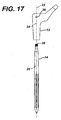
- FIGS. 16 and 19 show a hip stem 10 which is suitable for use with the alignment instrument in the kit of the present invention.
- the hip stem may be made of any suitable durable material which is compatible with the human body.
- the hip stem 10 may be made of a titanium alloy, a cobalt chromium alloy, or a stainless steel alloy.
- the hip stem 10 includes a proximal body 12 and a bowed distal stem 14.
- the proximal body 12 may be secured to the distal stem 14 in any suitable fashion.
- the proximal body 12 may be secured to the distal stem 14 by means of threads 15 located on the proximal portion of the proximal body 12 which are threadedly engaged to a nut 16.
- the distal stem 14 may include an external tapered portion 18 which mates with an internal tapered portion 20 of the proximal body 12.
- the taper of the internal tapered portion 20 and the external tapered portion 18 may be defined by an angle ⁇ .
- the taper is self-locking and has an angle of ⁇ , for example, approximately 18 degrees or less.
- the proximal body 12 and the distal stem 14 may either or both be rotatable around longitudinal centreline 22.
- the proximal body 22 may be rotatable in the direction of arrows 24 and the distal body may be rotated in the direction of arrows 26.
- FIGS. 17C and 17D a patient's femur is shown at 27.
- the natural femur has an anatomical anteversion.
- the normal femur is also bowed anteriorly.
- the anatomic anteversion angle ⁇ is defined by a plane, shown at 29 in FIGS. 17C and 17D , through the anterior bow 31 of the femur and a line through the centre of the femoral neck, shown at 33 in FIGS. 17C and 17D .
- the plane 29 corresponds with the position of the intramedullary canal.
- 17C and 17D corresponds generally with the bow of the femur and intramedullary canal. Since the stem of the prosthesis will be received in the intramedullary canal, in the present invention the anatomic anteversion of the femur can provide the basis for setting the prosthesis anteversion.
- the reference ⁇ is used for the anatomical anteversion angle as defined above; the reference ⁇ is used for the prosthetic or assembly anteversion angle.
- the prosthetic or assembly anteversion angle is defined by a plane through the bowed stem of the prosthesis and a line through the neck of the proximal part of the prosthesis.
- a trial anteversion angle ⁇ between a plane through the bowed stem and neck of the trial can be based on data gathered preoperatively and can be adjusted by the surgeon intraoperatively to adjust the trial; the surgeon can use this data to assemble the modular implant.
- Such a trial anteversion angle ⁇ is illustrated in FIG. 11 .
- the surgeon should be able to assemble a prosthesis such that the prosthetic or assembly anteversion angle ⁇ approximates the anatomical anteversion angle ⁇ .
- the present invention is not limited to any particular reference for the anatomic anteversion angle ⁇ .
- the anatomic anteversion angle could be determined from the position of the patient's foot with respect to the patient's shoulder line.
- the principles of the present invention could also be applied to other prosthetic joints, such as shoulders, and the reference for the anatomic anteversion angle will depend on anatomic features of the bones comprising that joint.
- the surgeon may determine that the optimum prosthetic anteversion angle ⁇ should vary somewhat from the anatomic anteversion angle ⁇ With the present invention, the surgeon can make such adjustments intraoperatively.
- the angular position between neck 32 of the proximal body 12 and the distal curved portion 34 of the curved distal stem 14 form the prosthetic anteversion angle ⁇ .
- the prosthetic anteversion angle ⁇ affects the patient's ability to walk and his gait.
- the hip stem 10 includes a proximal body location feature in the form of holes 36.
- the distal stem includes a distal stem location feature in the form of a slot 38.
- the proximal body location feature 36 and the distal stem location feature 38 may have any suitable shape and may be in the form of, for examples, slots, indents, triangles, squares, polygons, or any indexable feature.
- the slot 38 is shown in greater detail.
- the slot 38 may include two arcuate portions 39 defined by radius R extending from centre points 40.
- the centre points 40 may be spaced from each other a distance, for example A.
- the slot may have a depth T, of for example, 2,54 mm to 17,8 mm (0.1 to 0.7 inches).
- the distal stem 14 is shown in location where the arcuate shape of the distal stem is most pronounced.
- the curvature of the distal stem 14 may be defined by a radius R extending from distal stem centre point 42.
- the distal arcuate stem 14 is fitted into arcuate portion 44 of the medullary canal 46 of the femur 48.
- the distal stem 14 may further include a slot 49 to assist in the positioning of the arcuate femur 48 into the arcuate medullary canal 46 of the femur 48.
- Hip prosthesis assembly 50 includes stem 51.
- the stem 51 includes a proximal body 52 and a distal stem 54.
- the proximal body 52 of stem 51 may be secured to the distal stem 54 through an internal taper 62 in the proximal body 52 which is can be mated with the external taper 60 on the distal stem 54.
- the tapers 60 and 62 are preferably self-locking as in the stem 10.
- a ball or head 58 which mates with a cup (not shown) secured to a acetabulum (not shown) may be located on the proximal body 52.
- the distal stem 54 and the proximal body 52 may further be secured to each other by means of, for example, a nut 56 which is threadably engaged to a threaded portion 59 of the distal stem 54.
- the stem 51 includes a first location feature 66 (shown in FIG. 23 ) associated with the distal stem 54 and a second alignment feature 53 associated with the proximal body 52.
- the first alignment feature may be in the form of a recess 66 with a feature which can transmit torque.
- the first alignment feature 66 may be in the form of a triangular opening, a rectangular opening, a cross head screw slot, a through slot or as shown in FIG. 23 in the form of a oval slot.
- the slot 66 of the stem 51 may be made to similar dimensions to that of slot 38 of the hip stem 10.
- the hip stem 51 may include, in addition to the components already mentioned, a sleeve 72 which may mate with proximal body 52.
- the sleeve 72 may include a bore with an internal taper 74 which mates with external taper 76 on the proximal body 52.
- the sleeve 72 serves to provide additional support for the prosthesis 51 in the metaphyseal region and provides increased rotational stability for the prosthetic stem 51 when the stem is subjected to torsional loads.
- the second alignment feature 53 may be in the form of a pair of opposed holes which are similar to the holes 36 of the hip prosthesis 10.
- the hip stem 51 is shown in position in the long bone or femur 48.
- the proximal body 52 is shown in position with the neck 80 and the bowed portioned 82 of the distal stem 54 being out of angular alignment.
- the angle between the neck 80 and the arcuate portion 82 is defined as the prosthetic anteversion angle ⁇ .
- the distal stem 54 is shown out of angular position with the respect to normal femur geometry.
- the alignment device of the present invention permits the anteversion angle ⁇ for the prosthesis 51 as well as the anteversion angle ⁇ of the hip stem 10 of FIGS. 16 through 19 as well as the corresponding trials to be measured, and based upon a measured setting, the corresponding trial or implant to be set to that particular setting.
- the anteversion angle can be accurately set on an implant or a trial.
- orthopaedic surgeons utilize trials to place a substitute prosthetic item in the patient's body that can be removed after the trialing or verifying of the proper selection of the prosthesis. Once the dimensions of the trial are verified through reductions or movements of the patient's leg through the typical motions that the patient will require, the trial is removed and is sterilized to be used later for other surgeries. Conversely, a prosthetic implant once exposed to a patient is not utilized again. Therefore, it is important that the shape, position, and location of the appropriate trial be precisely duplicated by the actual implant. Thus, it may be very desirable to utilize an alignment device that can align a implant trial and preferably utilize the alignment determined by the implant trial and replicate the alignment in an implant.
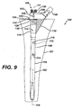
- the trial 100 includes a distal stem assembly 102 which is removably adjustably connected in a plurality of positions along longitudinal axis 104 of the distal stem assembly 102 to a neck trial 106.
- the distal stem assembly 102 may include a proximal stem portion 108 which is connected to a curved distal stem portion 110.
- the proximal stem portion 108 and the curved distal stem portion 110 may be integral or, as shown in FIG. 9 , the curved distal stem portion 110 may include a protrusion 112 which mates with a cavity 114 in the proximal stem portion 108.
- a pin 116 may be used to connect the proximal stem portion 108 to the curved distal stem portion 110.
- the neck trial 106 is connected to the distal stem assembly 102 in such a way that the angular position along centreline 104 between the neck trial 106 and the distal stem assembly 102 may be adjusted.
- the curved distal stem portion 110 may include an index mechanism 120 which permits a fixed degree of rotation adjustment between the neck trial 106 and the distal stem assembly 102.
- the index mechanism 120 may include a first gear or spline 122, as shown in FIG. 9 , rotatably keyed to the distal stem assembly 102.
- the index mechanism 120 may also include a second spline or gear 124 which may, as shown in FIG. 9 , be integral with the neck trial 106.
- the gears 122 and 124 may be rotatably adjustable or movable with respect to each in increments of, for example, 10 degrees.
- the index mechanism 120 may provide for 36 different relative positions of the neck trial 106 with respect to the distal stem assembly 102.
- the gears or splines 122 and 124 are selectively engaged and disengaged by means of, for example, a nut 126 variably secured to the distal stem assembly 102.
- the trial 100 may include a sleeve 130 which is used to replicate the sleeve 72 of the prosthesis 50, (see FIGS. 21 through 24 ).
- This sleeve 72 may be secured to the distal stem assembly 102 by a external tapered component 134 which forms a tapered sliding fit with the tapered bore 136 of the sleeve 130.
- the curved distal stem portion 110 is shown with the curved distal stem 110 showing the full extent of the curve.
- the curved distal stem portion 110 may be defined by example a radius RR extending from an origin 00.
- the radius RR may be, for example, four to eight inches, and may vary depending on the curvature of the patient's femur medullary canal.
- the neck trial portion 106 of the trial 100 may include a neck 140 to which a ball or head (not shown) may be used to fit against a acetabular cup (not shown) on the acetabulum of the patient (not shown).
- the trial 100 preferably includes locating features to determine the relative angular position ⁇ between neck centreline 142 and stem centreline 144.
- the neck trial 106 may include a body locating feature 146 while the distal stem assembly 102 may include a stem locating feature 148.
- the body locating feature 146 may be in the form of, for example, opposed cylindrical holes.
- the stem locating feature 148 may be, for example, in the form of a key-way or oval shaped slot in the proximal end of the distal stem assembly 102.
- the holes 146 may be similar in size and location to the holes 53 of the stem 51 and the holes 36 of the hip stem 10.
- the slot 148 of the trial 100 is preferably similar to the slot 38 of the prosthesis 10 and the slot 66 of the prosthesis 50.
- FIG. 1 shows an instrument 200 which may be utilized with either implants or trials.
- the instrument 200 may be utilized with the trial 100 of FIGS. 10 and 11 , or with the hip stem 10 of FIGS. 16 to 19 .
- the instrument 200 may be used with the hip stem assembly 51 of FIGS. 21 , 22 , 24 and 25 .
- the instrument 200 is used in conjunction with the relative angular orientation of a first component of a multi-piece prosthesis to a second component of the multi-piece prosthesis.
- the instrument 200 may be utilized to observe the relative angular orientation of the components or to replicate the angular orientation of the first component relative to the second component. While the instrument 200 may be adapted for any of a large number of designs of prosthetic components and prosthetic trial components, including the hip stem 10, the hip stem 51 and the trial 100, the instrument 200 will for simplicity now be described for use with the hip stem 51 of FIGS. 21 and 22 .
- the instrument 200 is utilized for at least one of observing or replicating the relative angular orientation of a first component, for example, proximal body 52, of a prosthesis with respect to a second component, for example, hip stem 54, of the prosthesis for use in joint arthroplasty.
- the instrument 200 includes a first member 202 for cooperation with the first component 52.
- the first member 202 may have any suitable size and shape capable for cooperation with the first component 52. As shown in FIG. 1 , the first member 202 may include a first member keyed feature 204. The first member keyed feature 204 cooperates with a first component key feature, for example, slot 66 of the first component 54. The key features 204 and 66 are used to angularly link the first member 202 with the first component 54. The key features 204 and 66 may have any suitable size and shape such that the first member 202 and the first component 54 are in timed engagement to provide a rotation and linkage of the first member 202 to the first component 54 about longitudinal centreline 206 of the instrument 200.
- the first member key feature 204 may be in the form, for example, of a recess or, as shown in FIG. 1 , in the form of a protrusion.
- the key feature 204 may be in the form of an oval protrusion. It should be appreciated that the keyed feature 204 may be a recess or a protrusion and may be, square, triangular, rectangular, a polygon or any shape capable of transmitting torque.
- the instrument 200 further includes a second member 210 for cooperation with the second component 52.
- the second member 210 may be in cooperation with the second component 52 in any suitable manner.
- the second member 210 may include a second member key feature 212, as shown in FIGS. 1 and 3 , which cooperates with, for example, the second component key feature in the form of holes 53.
- the second member key feature 212 may have any suitable form and may, for example, be in the form of a pin 212, a flat 214 on arm 216, or in the form of a yoke (not shown).
- the instrument 200 For the instrument 200 to cooperate with the holes 53 in the hip prosthesis 50, the instrument 200 includes the pin 212 extending inwardly from the arm 216. To enhance the stability of the instrument 200, the instrument 200 may further include a stabilizing member 218 similar to the second member 210 but being a mirror image of the second member 210 to attach to the opposite side of the second component 52. The stabilizing member 218 also includes arm 216, pin 212 and flat 214.
- the instrument 200 further includes a feature 220 for cooperation with the first member 202 and the second member 210 for at least one of replicating or observing the relative angular orientation of the first component 54 with respect to the second component 52.
- the feature 220 may be in the form of, for example a body. At least one of the first member 202 and the second member 210 are movably connected to the body 220.
- the body 220 serves the purpose of operably interconnecting the first member 202 to the second member 210. With the use of the body 220 the first member 202 may be positioned appropriately relative to the second member 210 to replicate or observe the relative angular orientation of the first component 54 with respect to the second component 52.
- the body 220 may include a longitudinal opening 222 in which an orientation rod 224 is slidably movable along longitudinal axis 206.
- the first member key feature 204 may be located on an end of the orientation rod 224.
- the orientation rod 224 may include a gripping feature 223 in the form of, for example, flats, knurls or splines for assisting in attempting to move the orientation rod 224 axially along longitudinal centreline 206 and to rotate the orientation rod 224 in the direction of arrows 226.
- the orientation rod 224 and the key feature 204 may be angularly orientated with respect to the body 220 electively permitting and preventing the orientation rod 224 from rotating in the direction of arrows 226. Such selective rotation of the orientation rod 224 may be accomplished by any method.
- the body 220 may include a locking arm 228 connected to a cam 230 by shaft 232 mounted to the body 220.
- the cam 230 may be utilized to selectively lock the orientation rod 224 in a fixed position with respect to the body 220 or, as shown in FIG.1 , may merely prevent the orientation rod 224 from rotating in the direction of arrows 226.
- the body 220 may further include a bushing or sleeve 234.
- the sleeve 234 is rotatably fitted to the opening 222 in the body 220.
- the cam 230 selectively engages the sleeve 234 to prevent and permit relative rotational motion of the sleeve 234 with respect to the body 220.
- the sleeve 234 may be operably connected to the orientation rod 224 such that the orientation rod 224 may move along the longitudinal axis 206 but be prohibited from relative motion with respect to the sleeve 234 rotationally in the direction of arrow 226.
- One method, as shown in FIG. 1 , of preventing rotation of the orientation rod 224 with respect to the sleeve 234 is by providing, for example, a longitudinal groove 236 in the orientation rod 224 which cooperates with a protrusion 240 extending inwardly from the sleeve 234.
- the instrument 200 may include a spring 242 positioned between the orientation rod 224 and the body 220 to urge the orientation rod 224 and the key feature 204 downwardly in the direction of arrow 244.
- the second member 210 is rotationally fixedly secured to the body 220 about longitudinal axis 206.
- the arm 216 may, as shown in FIG. 1 , pivot about pin 246 secured at hole 248 of the body 220.
- the stabilizing member 218 engages the other hole 53 if first component 54 at pin 212 and is pivotally positioned with respect to the body 220 at pin 246 secured to hole 248 in the body 220.
- the second member 210 and the stabilizing member 218 are preferably urged in the direction of arrows 250 toward the second component 52 by means of springs 252 positioned between the arm 216 and the body 220.
- the instrument 200 may include indicia 254 located on the instrument 200 to provide a measuring scale for the relative position of the first member 202 with respect to the body 220.
- the indicia 254 may have any suitable size and shape capable of providing the measurement capability for the instrument 200.
- the indicia 254 may, for example, include a single indicia in the form of a mark 256 extending axially along orientation rod 224.
- the indicia 254 may further include a plurality of indicia in the form of body indicia 260 located on the sleeve 234 of the body 220.
- the indicia may be in the form of characters, such as letters, or numbers, as shown at 262 in FIG.1 .
- Numbers 262 may be located adjacent their respective body indicia 260.
- the numbers 262 may correlate to, for example, a particular degree of anteversion.
- the instrument 200 of the present invention is shown in location on trial 100.
- the instrument 200 is secured in position on the trial 100.
- the pins 212 on the arm 216 are engaged in the holes 146 of the neck trial 106 of the trial 100.
- the key 204 of the orientation rod 224 of the instrument 200 is engaged in slot 146 of the stem assembly 102 of the trial 100.
- the neck trial 106 may rotate in the direction of arrows 226 with respect to the distal stem assembly 102.
- Stem centre- plane 144 and the neck centre-plane 142 define an included angle of the trial 100, which corresponds with the trial anteversion angle ⁇ .
- anatomic anteversion angle ⁇ By radiograph, CT scan or other imaging technique a patient's anatomic anteversion angle ⁇ may be determined. In typical cases, this anatomic anteversion angle ⁇ will be the optimum prosthetic anteversion angle ⁇ .
- the trial 100 may be set by the instrument 200 so that the trial anteversion angle ⁇ equals the optimum anteversion angle of, say, for example, 90 degrees.
- the nut 126 may be tightened onto the distal stem assembly 102, causing the index mechanism 120 to securely lock. Once securely locked, the index mechanism 120 may prevent the rotation of the neck 140 with respect to the distal stem assembly 102.
- the indicia 254 on the instrument 200 may be utilized either to set a predetermined anteversion angle determined by radiograph, CT scan, other imaging technique or by a common preset anteversion angle. It should be appreciated by utilizing the instrument 200 and the trial 100, the neck trial 106 may be rotated with respect to the distal stem assembly 102 an increment based on the index mechanism 120 of perhaps 10 degrees or less.
- the trial 100 may be preset utilizing instrument 200 to a particular first trial anteversion angle ⁇ .
- the trial 100 may then be inserted into a patient and a trial reduction performed. If the trial reduction indicates that the trial anteversion angle ⁇ should be increased or decreased, the nut 126 may be loosened enough to permit rotation of the index mechanism 120 and the proper amount of change of anteversion can be set by utilizing the indicia 254 and the instrument 200 or by merely listening to clicks as the index mechanism 120 is indexed appropriate number of teeth, with each tooth movement representing, for example, 10 degrees.
- the clinically selected correct anteversion can be measured by use of the instrument 200.
- the instrument 200 may be positioned into the trial 100 and the locking arm 228 moved from its unlocked position (shown in solid) to its locked position (shown in phantom).
- this desired setting may be repeated on, for example, an implant by reading the setting on the indicia 254 or by maintaining the instrument 200 in its locked position and utilizing the instrument 200 to properly preset an implant or stem prosthesis.
- the instrument 200 is shown in position on prosthetic hip stem 51. It should be appreciated that the instrument 200 may be similarly used on hip stem 10 of FIGS. 16 through 19 . It should also be appreciated that the instrument 200 may also be used with monolithic stems. Once the proper anteversion is determined by the instrument 200, a monolithic can be used with the determined anteversion.
- the proximal body 50 is loosely fitted to the distal stem 54.
- the neck 56 and body 52 are loosely fitted onto the distal stem 54 so that the proximal body 52 may rotate in the direction of arrows 226 with respect to the distal stem 54.
- the instrument 200 is engaged with the hip stem 54.
- the proximal body 52 will need to be rotated in the direction of the arrows 226 with respect to the distal stem 54 so that the key 204 may completely seat into the slot 66 of the distal stem 54 and so that the pin 212 may fully seat into the holes 53 in the hip proximal body 52.
- the distal end of the distal stem 54 may be slightly tapped in an upward direction to seat the proximal body 52 to the hip stem 51.
- the implant can be fixed with the proper anteversion angle between the neck centreline 85 and a plane 87 through the anterior bow of the stem 56.
- the centreline neck centreline forms the prosthetic anteversion angle ⁇ with the plane 87.
- the prosthetic anteversion angle ⁇ is virtually identical to the trial anteversion angle ⁇ of the trial. (See FIG. 12 )
- the plane 87 will correspond with the plane 29 through the anterior bow of the femur (See FIGS. 17C and 17D ) when the prosthetic is implanted, proper orientation of the prosthetic head and neck can be achieved.
- the instrument 200 may be removed. After removal of the instrument 200, the proximal body 54 may be securely seated onto the distal stem 54 by using tools (not shown) to fully lock the tapers 18, 20 and torque the nut 56 to the distal stem 54 finalizing the assembly of the stem 51.
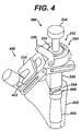
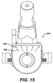
- FIGS. 4 through 8 show an orientation device 300 which is similar to the orientation device 200 of FIG. 1 .
- the orientation device 300 includes a body 320 which defines an opening 322. Within the opening 322 is a sleeve 334.
- An orientation rod 324 is slidably fitted to the sleeve 334.
- a locking arm 328 selectively locks the sleeve 334 to the body 320.
- a tang 304 on the distal end of the orientation rod 324 may engage a slot 466 in the proximal end of distal stem 454 of hip stem 400.
- An alignment fork 310 is slidably and rotationally fitted to the body 320. The alignment fork 310 engages the sides 453 of the neck 452 of hip stem 400.
- the locking arm 328 may be positioned in an unlocked position and the tang 304 angularly adjusted with respect to the alignment fork 310 until the alignment fork 310 and the tang 304 are properly seated into the proximal body 452 and the distal stem 454 of the hip stem 400, respectively.
- the fork 310 permits for adjustment in the directions of arrows 318, 320 and 321, providing sufficient adjustment for the fork 320 to centre a number of various designs for the neck of a prosthesis.
- the locking arm 328 may be moved from the locked position (shown in solid) to the unlocked position (shown in phantom).
- the orientation device 300 may include indicia 354 similar to the indicia 254 of the orientation device 200 of FIG. 1 .
- the indicia 354 may include a single indicia 324 located on sleeve 334 which cooperates with body indicia 360 on the body 320 to provide for a measurement of the anteversion of the hip stem 400. For example, as shown in FIG.
- the anteversion angle when the sleeve indicia 324 is aligned with the position 0 on the body indicia 360 of the body 320, the anteversion angle may be at the anteversion angle of zero; when the sleeve indicia 324 is aligned with the position 40 on the body indicia of the body 320, the anteversion angle may be at 40°, for example. It should be understood that these indicia are provided by way of example only, and the present invention is not limited to such indicia unless expressly called for in the claims.
- the instrument 300 is shown in position on the hip stem 400 in position on hip bone 99.
- the kit 500 is for use in joint arthroplasty and includes a prosthesis 502 for use in joint arthroplasty.
- the prosthesis 502 includes a first component 504 in the form of a proximal body and a second component 506 in the form of a distal stem.
- the kit 500 further includes an instrument 522 for angular orientation of the first component 504 to the second component 506 of the prosthesis 502.
- the instrument 522 includes a first member 524 cooperation with the first component 504 and a second member 526 cooperation with the second component 506 of the prosthesis 502.
- the instrument 522 may further include a feature 528 in the form of a sample body for cooperating with the first member 524 and the second member 526 for observing the relative angular orientation of the first member 524 with respect to the second member 526.
- the kit 500 may further include a trial 542.
- the trial 542 may include a first component 544 in the form of a proximal body and a second component 546 in the form of a distal stem.
- the method 700 includes a first step 702 of providing a trial prosthesis including a stem trial portion for implantation at least partially into the femoral canal of a femur and a neck trial portion extending from the stem portion.
- the method includes a second step 704 of positioning the stem trial portion into the femoral canal.
- the method includes a third step 706 of positioning the neck trial portion relative to the stem trial portion.
- the method 700 further includes another step 708 of securing the neck trial portion to the stem trial portion.
- the method further includes another step 710 of trialing the trial prosthesis.
- the method 700 also includes a step 712 of attaching an instrument to the stem trial portion and the neck trial portion.
- the method 700 further includes step 714 of measuring the relative position of the stem trial portion to the neck trial portion.
- the method 700 also includes the step 716 and 718 of providing an implant prosthesis including a stem implant portion for implantation at least partially into the canal of a long bone and a neck implant portion extending from the stem portion.
- the method 700 also includes step 720 of positioning the stem implant into the long bone canal.
- the method 700 also includes the step 722 of positioning the neck implant portion relative to the stem implant portion based upon the measured relative position of the stem trial portion to the neck trial portion.
- the method 700 also includes the step 724 of securing the neck implant portion to the stem implant portion.
- the method 700 may further include the step 726 of positioning the neck implant portion relative to the stem implant portion utilizing the instrument.
Landscapes
- Health & Medical Sciences (AREA)
- Orthopedic Medicine & Surgery (AREA)
- Transplantation (AREA)
- Life Sciences & Earth Sciences (AREA)
- Vascular Medicine (AREA)
- General Health & Medical Sciences (AREA)
- Biomedical Technology (AREA)
- Heart & Thoracic Surgery (AREA)
- Oral & Maxillofacial Surgery (AREA)
- Cardiology (AREA)
- Animal Behavior & Ethology (AREA)
- Engineering & Computer Science (AREA)
- Public Health (AREA)
- Veterinary Medicine (AREA)
- Biophysics (AREA)
- Nuclear Medicine, Radiotherapy & Molecular Imaging (AREA)
- Surgery (AREA)
- Physical Education & Sports Medicine (AREA)
- Prostheses (AREA)
Claims (10)
- Set zur Verwendung in einem chirurgischen Verfahren zum Implantieren einer orthopädischen Gelenkprothese, umfassend:(a) eine implantierbare Gelenkprothese (51) oder eine Probier-Gelenkprothese (100), die eine erste Komponente (52) und eine zweite Komponente (54) aufweist, wobei die erste und die zweite Komponente in unterschiedlichen Winkelausrichtungen zusammengesetzt werden können,(b) ein Instrument (200), um die relative Winkelausrichtung der ersten Komponente der Prothese zu der zweiten Komponente der Prothese zu replizieren und/oder zu messen, wobei das Instrument umfasst:ein erstes Element (202), das ein erstes Schlüsselmerkmal (204) zum Zusammenwirken mit einem entsprechenden Schlüsselmerkmal (66) auf der ersten Komponente aufweist, so dass das erste Element und die erste Komponente in Winkelrichtung gekoppelt sind,ein zweites Element (210), das ein Schlüsselmerkmal (212) zum Zusammenwirken mit einem entsprechenden Schlüsselmerkmal (53) auf der zweiten Komponente aufweist, undein Merkmal (220), das mit dem ersten Element und dem zweiten Element zusammenwirkt, um die relative Winkelausrichtung der ersten Komponente in Bezug auf die zweite Komponente zu replizieren und/oder zu messen,wobei sich das erste Element relativ zu dem zweiten Element drehen kann, um die unterschiedlichen Winkelausrichtungen der ersten Komponente relativ zu der zweiten Komponente in Einklang zu bringen, und wobei das Instrument ein Schloss (230) umfasst, um eine Relativbewegung zwischen dem ersten Element und dem zweiten Element selektiv zu verhindern.
- Set nach Anspruch 1, dadurch gekennzeichnet, dass das genannte Merkmal Anzeigemittel (254) auf dem ersten Element (202) oder auf dem zweiten Element (210) umfasst.
- Set nach Anspruch 1, dadurch gekennzeichnet, dass das erste Element (202) eine Vertiefung und/oder einen Vorsprung (204) zum Zusammenwirken mit der ersten Komponente (52) festlegt, und das zweite Element (210) ein Joch, einen Vorsprung (212) oder eine Vertiefung zum Zusammenwirken mit der zweiten Komponente (210) festlegt.
- Instrument nach Anspruch 1, dadurch gekennzeichnet, dass das genannte Merkmal eine Vielzahl von Anzeigemitteln (260) auf dem ersten Element (202) oder dem zweiten Element (210) umfasst, und ein Anzeigemittel (256) auf dem jeweils anderen des ersten Elements und des zweiten Elements.
- Set nach Anspruch 1, dadurch gekennzeichnet, dass das genannte erste Element (202) eine rotatorische Mittellinie des ersten Elements festlegt, und dass das genannte zweite Element (210) eine rotatorische Mittellinie des zweiten Elements festlegt, wobei die rotatorische Mittellinie des ersten Elements und die rotatorische Mittellinie des zweiten Elements miteinander übereinstimmen.
- Set nach Anspruch 1, dadurch gekennzeichnet, dass das genannte Merkmal einen Grundkörper (220) umfasst, wobei das genannte erste Element (202) und/oder das genannte zweite Element (210) an den genannten Grundkörper bewegbar angeglichen sind.
- Set nach Anspruch 6, dadurch gekennzeichnet, dass:das genannte erste Element (202), das genannte zweite Element (210) und der genannte Grundkörper (220) eine longitudinale Drehachse festlegen;das genannte erste Element oder das genannte zweite Element hinsichtlich einer Drehung mit dem genannten Grundkörper verriegelt ist;das andere des genannten ersten Elements und des genannten zweiten Elements in Bezug auf den genannten Grundkörper selektiv durch Drehung bewegbar ist, unddie relative Winkelposition des genannten ersten Elements in Bezug auf das genannte zweite Element um die longitudinale Achse der Winkelausrichtung der ersten Komponente in Bezug auf die zweite Komponente entspricht, wenn sich das genannte erste Element in Zusammenwirken mit der ersten Komponente befindet, und wenn sich das genannte zweite Element in Zusammenwirken mit der zweiten Komponente befindet.
- Set nach Anspruch 1, weiter umfassend einen Grundkörper (220), der eine Öffnung (220) durch diesen hindurch festlegt, wobei ein Abschnitt des genannten ersten Elements (202) durch Drehung in der Öffnung positioniert werden kann, wobei das genannte zweite Element (210) mit dem genannten Grundkörper verbunden ist.
- Set nach Anspruch 8, dadurch gekennzeichnet, dass das genannte erste Element (202) in Bezug auf die Öffnung (222) axial bewegbar ist.
- Set nach Anspruch 6, dadurch gekennzeichnet, dass das genannte zweite Element (210) schwenkbar mit dem genannten Grundkörper (220) verbunden ist.
Applications Claiming Priority (2)
| Application Number | Priority Date | Filing Date | Title |
|---|---|---|---|
| US10/327,196 US7022141B2 (en) | 2002-12-20 | 2002-12-20 | Alignment device for modular implants and method |
| US327196 | 2002-12-20 |
Publications (2)
| Publication Number | Publication Date |
|---|---|
| EP1437107A1 EP1437107A1 (de) | 2004-07-14 |
| EP1437107B1 true EP1437107B1 (de) | 2011-04-27 |
Family
ID=32507334
Family Applications (1)
| Application Number | Title | Priority Date | Filing Date |
|---|---|---|---|
| EP03257816A Expired - Lifetime EP1437107B1 (de) | 2002-12-20 | 2003-12-12 | Vorrichtung zum Ausrichten modularer Implantate |
Country Status (6)
| Country | Link |
|---|---|
| US (1) | US7022141B2 (de) |
| EP (1) | EP1437107B1 (de) |
| JP (1) | JP4237044B2 (de) |
| AT (1) | ATE506921T1 (de) |
| AU (1) | AU2003266452B2 (de) |
| DE (1) | DE60336883D1 (de) |
Families Citing this family (72)
| Publication number | Priority date | Publication date | Assignee | Title |
|---|---|---|---|---|
| US8795379B2 (en) | 2001-07-11 | 2014-08-05 | Biomet Manufacturing, Llc | Variable prosthesis |
| US6942699B2 (en) | 2001-07-11 | 2005-09-13 | Biomet, Inc. | Shoulder prosthesis |
| WO2003094802A1 (en) * | 2002-05-09 | 2003-11-20 | Hayes Medical, Inc. | System for establishing the orientation of a modular implant |
| US8062376B2 (en) * | 2002-07-10 | 2011-11-22 | Biomet Manufacturing Corp. | Shoulder implant assembly |
| US7001392B2 (en) * | 2003-01-29 | 2006-02-21 | Howmedica Osteonics Corp. | Apparatus and method for preparing bone for antirotational implantation of an orthopedic endoprosthesis |
| US7344565B2 (en) * | 2003-02-04 | 2008-03-18 | Wright Medical Technology, Inc. | Acetabular component insertion and extraction tool for use therewith, and method of locking an acetabular component to an insertion and extraction tool |
| US7074224B2 (en) * | 2003-06-25 | 2006-07-11 | Depuy Products, Inc. | Modular tapered reamer for bone preparation and associated method |
| US7297166B2 (en) | 2003-06-25 | 2007-11-20 | Depuy Products, Inc. | Assembly tool for modular implants and associated method |
| US20040267267A1 (en) | 2003-06-25 | 2004-12-30 | Daniels David Wayne | Non-linear reamer for bone preparation and associated method |
| US7582092B2 (en) | 2003-06-25 | 2009-09-01 | Depuy Products, Inc. | Assembly tool for modular implants and associated method |
| US8998919B2 (en) | 2003-06-25 | 2015-04-07 | DePuy Synthes Products, LLC | Assembly tool for modular implants, kit and associated method |
| US7338496B1 (en) * | 2003-08-29 | 2008-03-04 | Biomet Manufacturing Corp. | Method and apparatus for positioning an implant |
| US8070820B2 (en) * | 2003-10-08 | 2011-12-06 | Biomet Manufacturing Corp. | Shoulder implant assembly |
| US7785328B2 (en) * | 2003-12-30 | 2010-08-31 | Depuy Products, Inc. | Minimally invasive bone miller apparatus |
| US7575603B2 (en) * | 2004-05-28 | 2009-08-18 | Smith & Nephew, Inc. | Fluted intramedullary stem |
| US7892290B2 (en) * | 2004-05-28 | 2011-02-22 | Smith & Nephew, Inc. | Fluted sleeve hip prosthesis for modular stem |
| US20080281430A1 (en) * | 2005-02-22 | 2008-11-13 | Kelman David C | Long Sleeves for Use with Stems |
| US11457813B2 (en) | 2005-03-29 | 2022-10-04 | Martin W. Roche | Method for detecting body parameters |
| US20110213221A1 (en) | 2005-03-29 | 2011-09-01 | Roche Martin W | Method for Detecting Body Parameters |
| CA2600613C (en) * | 2005-03-29 | 2016-10-25 | Martin Roche | Body parameter detecting sensor and method for detecting body parameters |
| US7850696B2 (en) * | 2005-09-28 | 2010-12-14 | Depuy Products, Inc. | Device for facilitating reduction and repair of fractures of the small bones |
| EP1772106A1 (de) * | 2005-10-06 | 2007-04-11 | Zimmer GmbH | Instrument zum Vorbereiten und/oder Bearbeiten eines Femurkopfes |
| US10278711B2 (en) | 2006-02-27 | 2019-05-07 | Biomet Manufacturing, Llc | Patient-specific femoral guide |
| US20150335438A1 (en) | 2006-02-27 | 2015-11-26 | Biomet Manufacturing, Llc. | Patient-specific augments |
| US8407067B2 (en) | 2007-04-17 | 2013-03-26 | Biomet Manufacturing Corp. | Method and apparatus for manufacturing an implant |
| US9113971B2 (en) | 2006-02-27 | 2015-08-25 | Biomet Manufacturing, Llc | Femoral acetabular impingement guide |
| US9289253B2 (en) | 2006-02-27 | 2016-03-22 | Biomet Manufacturing, Llc | Patient-specific shoulder guide |
| US9345548B2 (en) | 2006-02-27 | 2016-05-24 | Biomet Manufacturing, Llc | Patient-specific pre-operative planning |
| US8603180B2 (en) | 2006-02-27 | 2013-12-10 | Biomet Manufacturing, Llc | Patient-specific acetabular alignment guides |
| US8591516B2 (en) | 2006-02-27 | 2013-11-26 | Biomet Manufacturing, Llc | Patient-specific orthopedic instruments |
| US9907659B2 (en) | 2007-04-17 | 2018-03-06 | Biomet Manufacturing, Llc | Method and apparatus for manufacturing an implant |
| US9173661B2 (en) | 2006-02-27 | 2015-11-03 | Biomet Manufacturing, Llc | Patient specific alignment guide with cutting surface and laser indicator |
| US9918740B2 (en) | 2006-02-27 | 2018-03-20 | Biomet Manufacturing, Llc | Backup surgical instrument system and method |
| US9339278B2 (en) | 2006-02-27 | 2016-05-17 | Biomet Manufacturing, Llc | Patient-specific acetabular guides and associated instruments |
| US9795399B2 (en) | 2006-06-09 | 2017-10-24 | Biomet Manufacturing, Llc | Patient-specific knee alignment guide and associated method |
| NZ548878A (en) * | 2006-08-01 | 2008-11-28 | Enztec Ltd | Improved impactor |
| US8597298B2 (en) | 2006-09-29 | 2013-12-03 | DePuy Synthes Products, LLC | Proximal reamer |
| US7585329B2 (en) * | 2006-11-28 | 2009-09-08 | Depuy Products, Inc. | Modular proximal body trial |
| US8491587B2 (en) * | 2006-12-21 | 2013-07-23 | Howmedica Osteonics Corp. | Adjustable offset bushing |
| GB0703691D0 (en) * | 2007-02-26 | 2007-04-04 | Benoist Girard Sas | Apparatus for Preparing A Prosthetic Stem Cavity in A Femur |
| US8556912B2 (en) * | 2007-10-30 | 2013-10-15 | DePuy Synthes Products, LLC | Taper disengagement tool |
| US8518050B2 (en) * | 2007-10-31 | 2013-08-27 | DePuy Synthes Products, LLC | Modular taper assembly device |
| US8221426B2 (en) * | 2008-02-12 | 2012-07-17 | Warsaw Orthopedic, Inc. | Methods and devices for deformity correction |
| US8167882B2 (en) * | 2008-09-30 | 2012-05-01 | Depuy Products, Inc. | Minimally invasive bone miller apparatus |
| US8333807B2 (en) * | 2010-03-05 | 2012-12-18 | Biomet Manufacturing Corp. | Method and apparatus for trialing and implanting a modular femoral hip |
| US8533921B2 (en) | 2010-06-15 | 2013-09-17 | DePuy Synthes Products, LLC | Spiral assembly tool |
| US9095452B2 (en) | 2010-09-01 | 2015-08-04 | DePuy Synthes Products, Inc. | Disassembly tool |
| US9271744B2 (en) | 2010-09-29 | 2016-03-01 | Biomet Manufacturing, Llc | Patient-specific guide for partial acetabular socket replacement |
| US9968376B2 (en) | 2010-11-29 | 2018-05-15 | Biomet Manufacturing, Llc | Patient-specific orthopedic instruments |
| US9241745B2 (en) | 2011-03-07 | 2016-01-26 | Biomet Manufacturing, Llc | Patient-specific femoral version guide |
| EP2856974B1 (de) | 2011-04-06 | 2017-03-01 | DePuy Synthes Products, LLC | Distale Reibahle |
| US9572682B2 (en) | 2011-09-29 | 2017-02-21 | Arthromeda, Inc. | System and method for precise prosthesis positioning in hip arthroplasty |
| US8702804B2 (en) | 2011-12-02 | 2014-04-22 | Biomet Manufacturing, Llc | Variable prosthesis |
| US9566172B2 (en) | 2013-03-14 | 2017-02-14 | Biomet Manufacturing, Llc. | Method and apparatus for determining a location |
| US9597096B2 (en) | 2013-03-15 | 2017-03-21 | Arthromeda, Inc. | Systems and methods for providing alignment in total knee arthroplasty |
| US9439785B2 (en) * | 2013-07-15 | 2016-09-13 | Zimmer, Inc. | Discretely adjustable hip-replacement trial |
| JP2018501905A (ja) | 2015-01-15 | 2018-01-25 | デピュイ・シンセス・プロダクツ・インコーポレイテッド | 組立工具 |
| EP3244837B1 (de) | 2015-01-15 | 2019-06-05 | DePuy Synthes Products, Inc. | Femurschaft mit einem anker zur vereinfachten montage und implantation |
| GB201514727D0 (en) | 2015-08-19 | 2015-09-30 | Depuy Ireland | An Assembly Tool |
| WO2017156221A1 (en) * | 2016-03-11 | 2017-09-14 | Jace Medical, Llc | Orthopaedic fixation devices, systems and methods |
| US10722310B2 (en) | 2017-03-13 | 2020-07-28 | Zimmer Biomet CMF and Thoracic, LLC | Virtual surgery planning system and method |
| GB201705917D0 (en) | 2017-04-12 | 2017-05-24 | Davidson Craig | Femoral trialling kit and assembly |
| GB201905459D0 (en) | 2019-04-17 | 2019-05-29 | Depuy Ireland Ultd Co | Indexable femoral neck resection guide |
| ES2899356T3 (es) * | 2019-04-26 | 2022-03-11 | Link Waldemar Gmbh Co | Pieza de cuello de ensayo para una endoprótesis de articulación |
| US11622869B2 (en) * | 2019-07-29 | 2023-04-11 | Tri-Sphere Holdings | Femoral component extractor |
| US11207197B2 (en) | 2019-08-01 | 2021-12-28 | DePuy Synthes Products, Inc. | Orthopaedic surgical instrument for total hip arthroplasty and associated orthopaedic surgical method of use |
| EP3824849A1 (de) * | 2019-11-19 | 2021-05-26 | Waldemar Link GmbH & Co. KG | Versatzselektor |
| US11617660B2 (en) * | 2020-06-12 | 2023-04-04 | Tri-Sphere Holdings, LLC | Femoral component extractor |
| TR202012007A2 (tr) * | 2020-07-28 | 2020-10-21 | Estas Eksantrik Sanayi Ve Ticaret Anonim Sirketi | Femural Head ve Asetabulum Kemik Deformasyonlarında Kullanılan Kalça Protez Sistemleri |
| US12127955B2 (en) | 2021-04-29 | 2024-10-29 | Depuy Ireland Unlimited Company | Trial component and method |
| US20230114445A1 (en) * | 2021-10-11 | 2023-04-13 | WishBone Medical, Inc. | Device for ex-situ implant orientation and assembly |
| US12496113B2 (en) * | 2022-03-02 | 2025-12-16 | Howmedica Osteonics Corp. | Bone reattachment system |
Family Cites Families (87)
| Publication number | Priority date | Publication date | Assignee | Title |
|---|---|---|---|---|
| US2492249A (en) * | 1947-09-02 | 1949-12-27 | Carl L Willard | Feed helix |
| US3271868A (en) * | 1963-08-07 | 1966-09-13 | Ortopedia Gmbh | Device for measuring two-dimensional representations |
| US3810312A (en) * | 1971-11-11 | 1974-05-14 | Const Supply Co | Alignment instrument |
| GB1373972A (en) * | 1972-03-09 | 1974-11-13 | Mckee G K | Artificial joints for the body |
| US4131998A (en) * | 1977-03-09 | 1979-01-02 | Spears Colin P | Tumor growth measurement device |
| FR2416002A1 (fr) | 1979-02-02 | 1979-08-31 | Science Union & Cie | Dispositif de mesure pour les condyles |
| FR2492249A1 (fr) | 1980-10-21 | 1982-04-23 | Deveze Yves | Appareil pour mesurer sur une radiographie les deviations vertebrales d'une colonne, dans un plan frontal et dans un plan antero-posterieur |
| US4608055A (en) * | 1984-01-12 | 1986-08-26 | Mayo Foundation | Femoral component for hip prosthesis |
| DE3417609A1 (de) * | 1984-05-11 | 1985-11-14 | Waldemar Link (Gmbh & Co), 2000 Hamburg | Anordnung zum herstellen einer anatomisch angemessenen endoprothese |
| DE3774799D1 (de) * | 1986-08-15 | 1992-01-09 | Boehringer Mannheim Corp., Indianapolis, Ind., Us | |
| US4716894A (en) * | 1986-08-27 | 1988-01-05 | Zimmer, Inc. | Acetabular cup inserting instrument |
| US5197989A (en) * | 1987-09-03 | 1993-03-30 | Hinckfuss Bruce W | Two stage joint prosthesis |
| US4964861A (en) | 1988-12-22 | 1990-10-23 | John M. Agee | Instrumentation for implanting prosthetic devices |
| US5108452A (en) * | 1989-02-08 | 1992-04-28 | Smith & Nephew Richards Inc. | Modular hip prosthesis |
| US4969911A (en) * | 1989-02-17 | 1990-11-13 | United States Manufacturing Company | Adjustable prosthetic joint with alignment means |
| US4917530A (en) * | 1989-08-31 | 1990-04-17 | Boehringer Mannheim Corporation | Structural joint |
| US5201882A (en) * | 1989-11-03 | 1993-04-13 | Paxson Robert D | Modular hip joint prosthesis with adjustable anteversion |
| US5135529A (en) * | 1989-11-03 | 1992-08-04 | Dow Corning Wright Corporation | Instrument for implanting modular hip joint prosthesis with adjustable anteversion and method of using said instrument |
| US5002581A (en) * | 1989-11-03 | 1991-03-26 | Dow Corning Wright Corporation | Modular hip joint prosthesis with adjustable anteversion |
| US5133760A (en) * | 1990-02-12 | 1992-07-28 | Alvarado Orthopedic Research, Inc. | Universal modular prosthesis stem extension |
| US5100407A (en) * | 1990-09-04 | 1992-03-31 | Pfizer Hospital Products Group, Inc. | Modular trial hip replacement system |
| US5064427A (en) * | 1991-05-14 | 1991-11-12 | Intermedics Orthopedics, Inc. | Apparatus for inserting and withdrawing humeral prosthesis |
| US5658349A (en) * | 1991-07-29 | 1997-08-19 | Joint Medical Products Corporation | Prosthetic joint system for bone replacement |
| FR2684287B3 (fr) | 1991-12-03 | 1994-03-11 | Chagneau Francis | Dispositif de controle du positionnement du membre inferieur lors d'une arthroplastie de la hanche. |
| EP0558203A1 (de) * | 1992-02-20 | 1993-09-01 | Wright Medical Technology, Inc. | Modulares Prüfinstrument mit Verriegelungsmechanismus |
| US5951606A (en) * | 1992-11-20 | 1999-09-14 | Burke; Dennis W. | Centering device for femoral implant and method and apparatus for implementation thereof |
| US5507824A (en) * | 1993-02-23 | 1996-04-16 | Lennox; Dennis W. | Adjustable prosthetic socket component, for articulating anatomical joints |
| FR2705558B1 (fr) | 1993-05-24 | 1995-07-28 | Medinov Sa | Prothèse de reconstruction de hanche et l'appareil de pose. |
| US5476466A (en) * | 1993-07-20 | 1995-12-19 | Zimmer, Inc. | Orthopaedic positioning instrument |
| US6197065B1 (en) * | 1993-11-01 | 2001-03-06 | Biomet, Inc. | Method and apparatus for segmental bone replacement |
| DE69431122T2 (de) * | 1993-12-22 | 2003-03-27 | St. Jude Medical, Inc. | Herzklappenhalter |
| ATE188370T1 (de) * | 1994-04-25 | 2000-01-15 | Sulzer Orthopaedie Ag | Ausziehinstrument für einen schaft einer hüftgelenkprothese oder einer entsprechenden raspel |
| EP0767638B1 (de) * | 1994-06-30 | 1999-07-07 | Howmedica Inc. | Modulares, femurales hüftgelenksprobesystem |
| US5514136A (en) * | 1994-09-06 | 1996-05-07 | Wright Medical Technology, Inc. | Surgical instrument for driving and rotating a long bone prosthesis |
| US5885299A (en) * | 1994-09-15 | 1999-03-23 | Surgical Dynamics, Inc. | Apparatus and method for implant insertion |
| DE4442204A1 (de) | 1994-11-19 | 1996-05-23 | Artos Med Produkte | Modulare Gelenkprothese |
| FR2730628B1 (fr) | 1995-01-27 | 1997-09-12 | Amp Dev | Prothese femorale modulaire a geometrie variable, notamment de reconstruction |
| US5607431A (en) * | 1995-02-09 | 1997-03-04 | Howmedica Inc. | Prosthetic hip implantation method and apparatus |
| US5609642A (en) * | 1995-02-15 | 1997-03-11 | Smith & Nephew Richards Inc. | Tibial trial prosthesis and bone preparation system |
| US5645607A (en) * | 1995-03-02 | 1997-07-08 | Zimmer, Inc. | Hip stem provisional having adjustable neck offsets |
| DE59606810D1 (de) * | 1995-11-20 | 2001-05-23 | Artos Med Produkte | Modulare endoprothese |
| US5858020A (en) * | 1995-12-05 | 1999-01-12 | Metagen, Llc | Modular prosthesis |
| US5766261A (en) * | 1996-02-01 | 1998-06-16 | Osteonics Corp. | Femoral revision broach with modular trial components and method |
| AU2054197A (en) * | 1996-02-21 | 1997-09-10 | Smith & Nephew, Inc. | Posterior stabilized/constrained reamer guide |
| US5935172A (en) * | 1996-06-28 | 1999-08-10 | Johnson & Johnson Professional, Inc. | Prosthesis with variable fit and strain distribution |
| DE29614349U1 (de) * | 1996-08-19 | 1997-12-18 | Waldemar Link GmbH & Co, 22339 Hamburg | Anordnung zum Einsetzen einer femoralen Knie-Gleitflächen-Endoprothese |
| US5876459A (en) * | 1996-08-30 | 1999-03-02 | Powell; Douglas Hunter | Adjustable modular orthopedic implant |
| US5906644A (en) * | 1996-08-30 | 1999-05-25 | Powell; Douglas Hunter | Adjustable modular orthopedic implant |
| US5879391A (en) * | 1996-09-30 | 1999-03-09 | Johnson & Johnson Professional, Inc. | Modular prosthesis |
| GB9623294D0 (en) * | 1996-11-08 | 1997-01-08 | Depuy Int Ltd | A broach for shaping a medullary cavity in a bone |
| US5810830A (en) * | 1996-11-13 | 1998-09-22 | Howmedica Inc. | Machining assembly and methods for preparing the medullary cavity of a femur in hip arthroplasty |
| US5993455A (en) * | 1996-11-13 | 1999-11-30 | Noble; Philip C. | Surgical broach and methods for preparing the medullary cavity of a femur in hip arthroplasty |
| US5951564A (en) * | 1996-12-18 | 1999-09-14 | Bristol-Myers Squibb Company | Orthopaedic positioning apparatus |
| US5728128A (en) * | 1997-02-11 | 1998-03-17 | Wright Medical Technology, Inc. | Femoral neck anteversion guide |
| US6206844B1 (en) * | 1997-02-28 | 2001-03-27 | Ethicon Endo-Surgery, Inc. | Reusable ultrasonic surgical instrument with removable outer sheath |
| US5860982A (en) * | 1997-03-26 | 1999-01-19 | Johnson & Johnson Professional, Inc. | Cemented calcar replacement varying height trial |
| US5792143A (en) * | 1997-04-21 | 1998-08-11 | Biomet, Inc | Neck length measuring device and method of using same for implanting a hip prosthesis |
| US5860969A (en) * | 1997-04-30 | 1999-01-19 | Biomet, Inc. | Version adjustment instrument for modular femoral components and method of using same |
| US5888245A (en) * | 1997-05-21 | 1999-03-30 | Bristol-Myers Squibb Company | Rotational alignment guide for a prosthetic hip stem implant and method of using same |
| DE69838917T2 (de) | 1997-06-27 | 2009-01-08 | Depuy Products, Inc., Warsaw | Modulare Hüftprobeprothese für lange Schäfte |
| US5976147A (en) * | 1997-07-11 | 1999-11-02 | Johnson & Johnson Professional, Inc | Modular instrumentation for bone preparation and implant trial reduction of orthopedic implants |
| US5849015A (en) * | 1997-09-11 | 1998-12-15 | Bristol-Myers Squibb Company | Orthopaedic stem inserter with quick release lever and ratchet |
| US5976188A (en) * | 1997-10-21 | 1999-11-02 | Johnson & Johnson Professional, Inc. | Modular prosthesis system with hybrid fixation |
| US5919195A (en) * | 1998-01-20 | 1999-07-06 | Johnson & Johnson Professional, Inc. | Oblong acetabular component instrumentation |
| GB9804473D0 (en) * | 1998-03-02 | 1998-04-29 | Benoist Girard & Cie | Prosthesis inserter |
| EP0940127B1 (de) * | 1998-03-02 | 2003-11-26 | Benoist Girard Sas | Prothesen-Einsetzvorrichtung |
| US6258095B1 (en) * | 1998-03-28 | 2001-07-10 | Stryker Technologies Corporation | Methods and tools for femoral intermedullary revision surgery |
| US6027507A (en) * | 1998-04-30 | 2000-02-22 | Innomed, Inc. | Leg length gauge for total hip surgery |
| US6071311A (en) * | 1998-08-14 | 2000-06-06 | Johnson & Johnson Professional, Inc. | Cylindrical box femoral stem |
| US5989259A (en) * | 1998-08-25 | 1999-11-23 | Johnson & Johnson Professional, Inc. | Femoral calcar stop for use with femoral stem inserter |
| US6080162A (en) * | 1998-09-28 | 2000-06-27 | Depuy Orthopaedics, Inc. | Modular orthopaedic clamping tool |
| US6264699B1 (en) | 1998-11-23 | 2001-07-24 | Depuy Orthopaedics, Inc. | Modular stem and sleeve prosthesis |
| US6165177A (en) * | 1998-12-24 | 2000-12-26 | Depuy Orthopaedics, Inc. | Alignment guide for insertion of stem prosthesis |
| US6102950A (en) * | 1999-01-19 | 2000-08-15 | Vaccaro; Alex | Intervertebral body fusion device |
| US6277123B1 (en) * | 1999-09-10 | 2001-08-21 | Depuy Orthopaedics, Inc. | Prosthesis positioning apparatus and method for implanting a prosthesis |
| DE60018712T2 (de) * | 1999-02-03 | 2006-03-16 | Synthes Ag Chur, Chur | Chirurgischer bohrer |
| US6126694A (en) * | 1999-03-05 | 2000-10-03 | Sulzer Orthopedics Inc. | Universal distal broach and stem trial |
| US6117138A (en) * | 1999-04-16 | 2000-09-12 | Sulzer Orthopedics Inc. | Instruments for forming bony cavity for implantable femoral, hip prosthesis |
| US6270529B1 (en) * | 1999-09-01 | 2001-08-07 | Wright Medical Technology, Inc. | Modular implant for replacing end of radius and having drainage passage for trapped fluid |
| US6224605B1 (en) * | 1999-11-24 | 2001-05-01 | Bristol-Myers Squibb Co. | Orthopaedic instrumentation assembly and method of using same |
| US6238435B1 (en) * | 2000-03-10 | 2001-05-29 | Bristol-Myers Squibb Co | Assembly tool for prosthetic implant |
| US6319286B1 (en) * | 2000-03-13 | 2001-11-20 | Exactech, Inc | Modular hip prosthesis |
| WO2001082843A2 (en) | 2000-05-03 | 2001-11-08 | Smith & Nephew, Inc. | Multi modular trialing system and instrumentation |
| US6330845B1 (en) * | 2000-05-17 | 2001-12-18 | Bristol-Myers Squibb | Wrench for an implant |
| US6258097B1 (en) * | 2000-06-02 | 2001-07-10 | Bristol-Myers Squibb Co | Head center instrument and method of using the same |
| DE20014377U1 (de) | 2000-08-19 | 2002-01-10 | Stratec Medical Ag, Oberdorf | Vorrichtung zur Optimierung einer Knie-Endoprothese |
| US6355068B1 (en) * | 2001-06-07 | 2002-03-12 | Hammill Manufacturing Co. | Sight gauge modular joint and method |
-
2002
- 2002-12-20 US US10/327,196 patent/US7022141B2/en not_active Expired - Lifetime
-
2003
- 2003-12-03 AU AU2003266452A patent/AU2003266452B2/en not_active Ceased
- 2003-12-12 EP EP03257816A patent/EP1437107B1/de not_active Expired - Lifetime
- 2003-12-12 DE DE60336883T patent/DE60336883D1/de not_active Expired - Lifetime
- 2003-12-12 AT AT03257816T patent/ATE506921T1/de not_active IP Right Cessation
- 2003-12-19 JP JP2003422853A patent/JP4237044B2/ja not_active Expired - Fee Related
Also Published As
| Publication number | Publication date |
|---|---|
| EP1437107A1 (de) | 2004-07-14 |
| AU2003266452A1 (en) | 2004-07-08 |
| JP4237044B2 (ja) | 2009-03-11 |
| ATE506921T1 (de) | 2011-05-15 |
| DE60336883D1 (de) | 2011-06-09 |
| US7022141B2 (en) | 2006-04-04 |
| JP2004202231A (ja) | 2004-07-22 |
| AU2003266452B2 (en) | 2008-06-12 |
| US20040122437A1 (en) | 2004-06-24 |
Similar Documents
| Publication | Publication Date | Title |
|---|---|---|
| EP1437107B1 (de) | Vorrichtung zum Ausrichten modularer Implantate | |
| US7854737B2 (en) | Instrument and associated method of trailing for modular hip stems | |
| EP1491149B1 (de) | Gelenkfräsvorrichtung | |
| EP1482878B1 (de) | Intramedulläre trial-fixiervorrichtung | |
| US8790346B2 (en) | Modular tapered reamer for bone preparation and associated method | |
| US8048167B2 (en) | Orthopaedic implant kit, orthopaedic surgery kit and associated method | |
| EP1430859B1 (de) | Verstellbare biomechanische Messvorrichtung | |
| EP2301481B9 (de) | Ausziehbare umgekehrte Probeschulter | |
| EP1905397B1 (de) | Instrumentenkit für eine modulare orthopädische Prothese | |
| GB2564718A (en) | Apparatus and method for hip surgery |
Legal Events
| Date | Code | Title | Description |
|---|---|---|---|
| PUAI | Public reference made under article 153(3) epc to a published international application that has entered the european phase |
Free format text: ORIGINAL CODE: 0009012 |
|
| AK | Designated contracting states |
Kind code of ref document: A1 Designated state(s): AT BE BG CH CY CZ DE DK EE ES FI FR GB GR HU IE IT LI LU MC NL PT RO SE SI SK TR |
|
| AX | Request for extension of the european patent |
Extension state: AL LT LV MK |
|
| 17P | Request for examination filed |
Effective date: 20041217 |
|
| AKX | Designation fees paid |
Designated state(s): AT BE BG CH CY CZ DE DK EE ES FI FR GB GR HU IE IT LI LU MC NL PT RO SE SI SK TR |
|
| 17Q | First examination report despatched |
Effective date: 20091221 |
|
| GRAP | Despatch of communication of intention to grant a patent |
Free format text: ORIGINAL CODE: EPIDOSNIGR1 |
|
| GRAS | Grant fee paid |
Free format text: ORIGINAL CODE: EPIDOSNIGR3 |
|
| GRAA | (expected) grant |
Free format text: ORIGINAL CODE: 0009210 |
|
| AK | Designated contracting states |
Kind code of ref document: B1 Designated state(s): AT BE BG CH CY CZ DE DK EE ES FI FR GB GR HU IE IT LI LU MC NL PT RO SE SI SK TR |
|
| REG | Reference to a national code |
Ref country code: GB Ref legal event code: FG4D |
|
| REG | Reference to a national code |
Ref country code: CH Ref legal event code: EP |
|
| REG | Reference to a national code |
Ref country code: IE Ref legal event code: FG4D |
|
| REF | Corresponds to: |
Ref document number: 60336883 Country of ref document: DE Date of ref document: 20110609 Kind code of ref document: P |
|
| REG | Reference to a national code |
Ref country code: DE Ref legal event code: R096 Ref document number: 60336883 Country of ref document: DE Effective date: 20110609 |
|
| REG | Reference to a national code |
Ref country code: NL Ref legal event code: VDEP Effective date: 20110427 |
|
| PG25 | Lapsed in a contracting state [announced via postgrant information from national office to epo] |
Ref country code: PT Free format text: LAPSE BECAUSE OF FAILURE TO SUBMIT A TRANSLATION OF THE DESCRIPTION OR TO PAY THE FEE WITHIN THE PRESCRIBED TIME-LIMIT Effective date: 20110829 Ref country code: SE Free format text: LAPSE BECAUSE OF FAILURE TO SUBMIT A TRANSLATION OF THE DESCRIPTION OR TO PAY THE FEE WITHIN THE PRESCRIBED TIME-LIMIT Effective date: 20110427 |
|
| PG25 | Lapsed in a contracting state [announced via postgrant information from national office to epo] |
Ref country code: AT Free format text: LAPSE BECAUSE OF FAILURE TO SUBMIT A TRANSLATION OF THE DESCRIPTION OR TO PAY THE FEE WITHIN THE PRESCRIBED TIME-LIMIT Effective date: 20110427 Ref country code: GR Free format text: LAPSE BECAUSE OF FAILURE TO SUBMIT A TRANSLATION OF THE DESCRIPTION OR TO PAY THE FEE WITHIN THE PRESCRIBED TIME-LIMIT Effective date: 20110728 Ref country code: ES Free format text: LAPSE BECAUSE OF FAILURE TO SUBMIT A TRANSLATION OF THE DESCRIPTION OR TO PAY THE FEE WITHIN THE PRESCRIBED TIME-LIMIT Effective date: 20110807 Ref country code: SI Free format text: LAPSE BECAUSE OF FAILURE TO SUBMIT A TRANSLATION OF THE DESCRIPTION OR TO PAY THE FEE WITHIN THE PRESCRIBED TIME-LIMIT Effective date: 20110427 Ref country code: CY Free format text: LAPSE BECAUSE OF FAILURE TO SUBMIT A TRANSLATION OF THE DESCRIPTION OR TO PAY THE FEE WITHIN THE PRESCRIBED TIME-LIMIT Effective date: 20110427 Ref country code: FI Free format text: LAPSE BECAUSE OF FAILURE TO SUBMIT A TRANSLATION OF THE DESCRIPTION OR TO PAY THE FEE WITHIN THE PRESCRIBED TIME-LIMIT Effective date: 20110427 Ref country code: BE Free format text: LAPSE BECAUSE OF FAILURE TO SUBMIT A TRANSLATION OF THE DESCRIPTION OR TO PAY THE FEE WITHIN THE PRESCRIBED TIME-LIMIT Effective date: 20110427 |
|
| PG25 | Lapsed in a contracting state [announced via postgrant information from national office to epo] |
Ref country code: NL Free format text: LAPSE BECAUSE OF FAILURE TO SUBMIT A TRANSLATION OF THE DESCRIPTION OR TO PAY THE FEE WITHIN THE PRESCRIBED TIME-LIMIT Effective date: 20110427 |
|
| PG25 | Lapsed in a contracting state [announced via postgrant information from national office to epo] |
Ref country code: CZ Free format text: LAPSE BECAUSE OF FAILURE TO SUBMIT A TRANSLATION OF THE DESCRIPTION OR TO PAY THE FEE WITHIN THE PRESCRIBED TIME-LIMIT Effective date: 20110427 Ref country code: EE Free format text: LAPSE BECAUSE OF FAILURE TO SUBMIT A TRANSLATION OF THE DESCRIPTION OR TO PAY THE FEE WITHIN THE PRESCRIBED TIME-LIMIT Effective date: 20110427 |
|
| PG25 | Lapsed in a contracting state [announced via postgrant information from national office to epo] |
Ref country code: RO Free format text: LAPSE BECAUSE OF FAILURE TO SUBMIT A TRANSLATION OF THE DESCRIPTION OR TO PAY THE FEE WITHIN THE PRESCRIBED TIME-LIMIT Effective date: 20110427 Ref country code: DK Free format text: LAPSE BECAUSE OF FAILURE TO SUBMIT A TRANSLATION OF THE DESCRIPTION OR TO PAY THE FEE WITHIN THE PRESCRIBED TIME-LIMIT Effective date: 20110427 Ref country code: SK Free format text: LAPSE BECAUSE OF FAILURE TO SUBMIT A TRANSLATION OF THE DESCRIPTION OR TO PAY THE FEE WITHIN THE PRESCRIBED TIME-LIMIT Effective date: 20110427 |
|
| PLBE | No opposition filed within time limit |
Free format text: ORIGINAL CODE: 0009261 |
|
| STAA | Information on the status of an ep patent application or granted ep patent |
Free format text: STATUS: NO OPPOSITION FILED WITHIN TIME LIMIT |
|
| 26N | No opposition filed |
Effective date: 20120130 |
|
| REG | Reference to a national code |
Ref country code: DE Ref legal event code: R097 Ref document number: 60336883 Country of ref document: DE Effective date: 20120130 |
|
| PG25 | Lapsed in a contracting state [announced via postgrant information from national office to epo] |
Ref country code: IT Free format text: LAPSE BECAUSE OF FAILURE TO SUBMIT A TRANSLATION OF THE DESCRIPTION OR TO PAY THE FEE WITHIN THE PRESCRIBED TIME-LIMIT Effective date: 20110427 |
|
| PG25 | Lapsed in a contracting state [announced via postgrant information from national office to epo] |
Ref country code: MC Free format text: LAPSE BECAUSE OF NON-PAYMENT OF DUE FEES Effective date: 20111231 |
|
| REG | Reference to a national code |
Ref country code: CH Ref legal event code: PL |
|
| GBPC | Gb: european patent ceased through non-payment of renewal fee |
Effective date: 20111212 |
|
| REG | Reference to a national code |
Ref country code: FR Ref legal event code: ST Effective date: 20120831 |
|
| REG | Reference to a national code |
Ref country code: IE Ref legal event code: MM4A |
|
| REG | Reference to a national code |
Ref country code: DE Ref legal event code: R119 Ref document number: 60336883 Country of ref document: DE Effective date: 20120703 |
|
| PG25 | Lapsed in a contracting state [announced via postgrant information from national office to epo] |
Ref country code: IE Free format text: LAPSE BECAUSE OF NON-PAYMENT OF DUE FEES Effective date: 20111212 Ref country code: GB Free format text: LAPSE BECAUSE OF NON-PAYMENT OF DUE FEES Effective date: 20111212 Ref country code: CH Free format text: LAPSE BECAUSE OF NON-PAYMENT OF DUE FEES Effective date: 20111231 Ref country code: DE Free format text: LAPSE BECAUSE OF NON-PAYMENT OF DUE FEES Effective date: 20120703 Ref country code: LI Free format text: LAPSE BECAUSE OF NON-PAYMENT OF DUE FEES Effective date: 20111231 |
|
| PG25 | Lapsed in a contracting state [announced via postgrant information from national office to epo] |
Ref country code: FR Free format text: LAPSE BECAUSE OF NON-PAYMENT OF DUE FEES Effective date: 20120102 |
|
| PG25 | Lapsed in a contracting state [announced via postgrant information from national office to epo] |
Ref country code: LU Free format text: LAPSE BECAUSE OF NON-PAYMENT OF DUE FEES Effective date: 20111212 |
|
| PG25 | Lapsed in a contracting state [announced via postgrant information from national office to epo] |
Ref country code: BG Free format text: LAPSE BECAUSE OF FAILURE TO SUBMIT A TRANSLATION OF THE DESCRIPTION OR TO PAY THE FEE WITHIN THE PRESCRIBED TIME-LIMIT Effective date: 20110727 |
|
| PG25 | Lapsed in a contracting state [announced via postgrant information from national office to epo] |
Ref country code: TR Free format text: LAPSE BECAUSE OF FAILURE TO SUBMIT A TRANSLATION OF THE DESCRIPTION OR TO PAY THE FEE WITHIN THE PRESCRIBED TIME-LIMIT Effective date: 20110427 |
|
| PG25 | Lapsed in a contracting state [announced via postgrant information from national office to epo] |
Ref country code: HU Free format text: LAPSE BECAUSE OF FAILURE TO SUBMIT A TRANSLATION OF THE DESCRIPTION OR TO PAY THE FEE WITHIN THE PRESCRIBED TIME-LIMIT Effective date: 20110427 |