EP1437185A1 - Méthode de fabrication d' une jante en alliage léger - Google Patents
Méthode de fabrication d' une jante en alliage léger Download PDFInfo
- Publication number
- EP1437185A1 EP1437185A1 EP20030000222 EP03000222A EP1437185A1 EP 1437185 A1 EP1437185 A1 EP 1437185A1 EP 20030000222 EP20030000222 EP 20030000222 EP 03000222 A EP03000222 A EP 03000222A EP 1437185 A1 EP1437185 A1 EP 1437185A1
- Authority
- EP
- European Patent Office
- Prior art keywords
- strip
- wheel rim
- gap
- lower molds
- curve
- Prior art date
- Legal status (The legal status is an assumption and is not a legal conclusion. Google has not performed a legal analysis and makes no representation as to the accuracy of the status listed.)
- Withdrawn
Links
- 238000004519 manufacturing process Methods 0.000 title claims abstract description 14
- 229910000838 Al alloy Inorganic materials 0.000 title claims abstract description 12
- 238000000034 method Methods 0.000 title claims description 21
- 238000003466 welding Methods 0.000 claims abstract description 8
- 238000001125 extrusion Methods 0.000 claims abstract description 5
- 238000003825 pressing Methods 0.000 claims description 9
- 238000005476 soldering Methods 0.000 claims description 3
- 238000003801 milling Methods 0.000 claims description 2
- 229910000679 solder Inorganic materials 0.000 claims description 2
- 238000005520 cutting process Methods 0.000 claims 1
- 239000000463 material Substances 0.000 description 5
- 229910052782 aluminium Inorganic materials 0.000 description 3
- XAGFODPZIPBFFR-UHFFFAOYSA-N aluminium Chemical compound [Al] XAGFODPZIPBFFR-UHFFFAOYSA-N 0.000 description 3
- 238000005498 polishing Methods 0.000 description 3
- 238000000137 annealing Methods 0.000 description 2
- 238000005452 bending Methods 0.000 description 2
- 238000010438 heat treatment Methods 0.000 description 2
- 238000007493 shaping process Methods 0.000 description 2
- 230000002411 adverse Effects 0.000 description 1
- 230000006835 compression Effects 0.000 description 1
- 238000007906 compression Methods 0.000 description 1
- 238000005265 energy consumption Methods 0.000 description 1
- 229910052751 metal Inorganic materials 0.000 description 1
- 239000002184 metal Substances 0.000 description 1
- 239000007769 metal material Substances 0.000 description 1
- 238000012986 modification Methods 0.000 description 1
- 230000004048 modification Effects 0.000 description 1
- 238000000465 moulding Methods 0.000 description 1
- 238000004904 shortening Methods 0.000 description 1
Images



Classifications
-
- B—PERFORMING OPERATIONS; TRANSPORTING
- B23—MACHINE TOOLS; METAL-WORKING NOT OTHERWISE PROVIDED FOR
- B23K—SOLDERING OR UNSOLDERING; WELDING; CLADDING OR PLATING BY SOLDERING OR WELDING; CUTTING BY APPLYING HEAT LOCALLY, e.g. FLAME CUTTING; WORKING BY LASER BEAM
- B23K1/00—Soldering, e.g. brazing, or unsoldering
- B23K1/14—Soldering, e.g. brazing, or unsoldering specially adapted for soldering seams
- B23K1/18—Soldering, e.g. brazing, or unsoldering specially adapted for soldering seams circumferential seams, e.g. of shells
-
- B—PERFORMING OPERATIONS; TRANSPORTING
- B21—MECHANICAL METAL-WORKING WITHOUT ESSENTIALLY REMOVING MATERIAL; PUNCHING METAL
- B21D—WORKING OR PROCESSING OF SHEET METAL OR METAL TUBES, RODS OR PROFILES WITHOUT ESSENTIALLY REMOVING MATERIAL; PUNCHING METAL
- B21D53/00—Making other particular articles
- B21D53/26—Making other particular articles wheels or the like
- B21D53/30—Making other particular articles wheels or the like wheel rims
-
- B—PERFORMING OPERATIONS; TRANSPORTING
- B60—VEHICLES IN GENERAL
- B60B—VEHICLE WHEELS; CASTORS; AXLES FOR WHEELS OR CASTORS; INCREASING WHEEL ADHESION
- B60B21/00—Rims
-
- B—PERFORMING OPERATIONS; TRANSPORTING
- B23—MACHINE TOOLS; METAL-WORKING NOT OTHERWISE PROVIDED FOR
- B23K—SOLDERING OR UNSOLDERING; WELDING; CLADDING OR PLATING BY SOLDERING OR WELDING; CUTTING BY APPLYING HEAT LOCALLY, e.g. FLAME CUTTING; WORKING BY LASER BEAM
- B23K2103/00—Materials to be soldered, welded or cut
- B23K2103/08—Non-ferrous metals or alloys
- B23K2103/10—Aluminium or alloys thereof
Definitions
- the present invention relates to the field of wheel rim manufacturing and more particularly to an improved method of manufacturing an aluminum alloy wheel rim.
- FIGS. 1 to 3 The method of Evans's Patent is illustrated in FIGS. 1 to 3.
- a strip 1 of aluminum sheet material used to form a wheel rim is shown.
- FIG. 2 such strip 1 is formed into a hoop 3 and the opposing ends flash butt welded forming weld line 2.
- the thus formed hoop is subsequently passed through multiple forming operations (e.g., press and roll forming operations) resulting in a finished wheel rim 4 having desired sectional profiles shown in FIG. 3.
- It is therefore an object of the present invention to provide a method of manufacturing a wheel rim for a motor vehicle comprising the steps of (a) forming a strip of aluminum alloy sheet material having a predetermined cross-section suitable for forming into a wheel rim by extrusion molding; (b) pressing the strip step-by-step lengthwise by an upper mold and a lower mold having complimentary profiles for causing the strip to have predetermined profiles as a hoop with a formed gap between the both ends; (c) welding the gap to form an unfinished wheel rim; and (d) annealing, shaping, heat treating, and polishing the unfinished wheel rim to form a finished wheel rim.
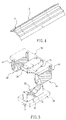
- FIGS. 4 to 6 there is shown a method of manufacturing an aluminum alloy wheel rim in accordance with the invention comprising the steps of extrusion molding an aluminum alloy into a strip 10 of aluminum alloy sheet material having a predetermined cross-section suitable for forming into a wheel rim, pressing the strip 10 by an upper mold 20 and a lower mold 30 respectively, and bending both ends of strip 10 to form a bent end having a predetermined curvature ⁇ .
- FIGS. 4 and 5 show a first preferred embodiment of the invention.
- Upper mold 20 and lower mold 30 are coupled to and activated by a lever 28 and a seat 38 of a hydraulic press respectively.
- the pressing sides 21 and 32 of upper mold 20 and lower mold 30 have cross-sections which conform with the predetermined cross-section of the strip 10, thereby allowing the strip 10 to be placed between molds 20 and 30.
- a roller 40 is provided on either side of the upper mold 20.
- the wheel mounts 41 of roller 40 are also coupled to and activated by the lever 28 of the hydraulic press. In the manufacturing processes, both ends of strip 10 are bent by the upper mold 20 and lower mold 30 first to form a predetermined curvature ⁇ .
- the pressing sides 21 and 32 of the upper mold 20 and lower mold 30 will press on the strip 10 and apply bending forces to the strip 10 along the longitudinal axis of the strip 10 in opposite directions, thus forming a predetermined curvature ⁇ on the position being pressed.
- the degree of curvature ⁇ is preferably in the range between 15 to 60 degrees.
- the radius of curvature ⁇ is substantially the same as that of formed wheel rim.
- the roller 40 will push the unchanged section of strip 10 adjacent to the deformed section to a position continuously along the curvature ⁇ in order to prevent an undesired discontinuous deformation of strip 10 between the formed section of strip 10 and the adjacent unchanged section thereof.
- both ends of strip 10 are bent to form a predetermined curvature ⁇
- a lengthwise non-uniform deformation exists in both ends of strip 10 due to molecular compression of the metal strip 10.
- the deformation ⁇ L c in the center of the lengthwise direction of strip 10 is larger than ⁇ L s in either side thereof, as shown in Fig. 7.
- a non-uniform deformation ⁇ L on either end of strip 10 will be cut out by a bench saw as shown in FIG. 8. and only a desired length L of strip 10 will be preserved.
- a milling machine is used to form a guide angle on either end of strip 10.
- both ends of strip 10 may be proximate to each other after strip 10 is formed as a hoop.
- strip 10 is again placed between molds 20 and 30.
- the unchanged section of strip 10 is pressed step-by-step by molds 20 and 30 lengthwise and bend subsequently to form a hoop 50 (referring to FIG. 9) having a V-shaped gap 51 formed between both ends thereof.
- a point soldering 60 is performed on the gap 51 for partially connecting both ends of hoop 50 together.
- welding is performed on V-shaped gap 51 to melt the aluminum alloy solder 61 so as to unite the both ends of strip 10 together ( referring to FIG. 10).
- An unfinished wheel rim 50 is thus formed.
- the unfinished wheel rim 50 is annealed to eliminate stress concentration in the gap 51 portion. After being annealed, the unfinished wheel rim 50 is placed between an upper mold 81 and a lower mold 82 of another hydraulic press where the upper mold 81 and lower mold 82 are activated by another hydraulic press respectively to form a wheel rim having the same profiles as the junction of molds 81 and 82 (since molds 81 and 82 have complimentary profiles), as shown in Fig. 11. Also, any irregularity formed on the unfinished wheel rim 50 will be eliminated after molds 81 and 82 press on the inner face of unfinished wheel rim 50. This substantially forms an unfinished wheel rim 50 having a desired size.
- a strip 10 of aluminum alloy sheet material having a predetermined cross-section suitable for forming into a wheel rim by extrusion molding further comprises a lengthwise rib 11 thereon.
- strip 10 is then placed between molds 20 and 30 facing a pressing side 21 and a pressing side 32 thereof respectively.
- Upper mold 20 and lower mold 30 are activated by a hydraulic press.
- a well 31 is provided on pressing side 32 sized to receive the rib 11.
- a series of forming operations e.g., press and roll forming operations
- the equipment required is simple and inexpensive.
- the quality of formed aluminum alloy wheel rim is high.
- No welding operation is required for fastening wheel rim 50 and disk 70.
- the provision of rib 11 greatly enhances the strength of finished wheel rim 50.
Landscapes
- Engineering & Computer Science (AREA)
- Mechanical Engineering (AREA)
- Forging (AREA)
Priority Applications (1)
| Application Number | Priority Date | Filing Date | Title |
|---|---|---|---|
| EP20030000222 EP1437185A1 (fr) | 2003-01-07 | 2003-01-07 | Méthode de fabrication d' une jante en alliage léger |
Applications Claiming Priority (1)
| Application Number | Priority Date | Filing Date | Title |
|---|---|---|---|
| EP20030000222 EP1437185A1 (fr) | 2003-01-07 | 2003-01-07 | Méthode de fabrication d' une jante en alliage léger |
Publications (1)
| Publication Number | Publication Date |
|---|---|
| EP1437185A1 true EP1437185A1 (fr) | 2004-07-14 |
Family
ID=32479885
Family Applications (1)
| Application Number | Title | Priority Date | Filing Date |
|---|---|---|---|
| EP20030000222 Withdrawn EP1437185A1 (fr) | 2003-01-07 | 2003-01-07 | Méthode de fabrication d' une jante en alliage léger |
Country Status (1)
| Country | Link |
|---|---|
| EP (1) | EP1437185A1 (fr) |
Cited By (1)
| Publication number | Priority date | Publication date | Assignee | Title |
|---|---|---|---|---|
| CN109848250A (zh) * | 2018-11-22 | 2019-06-07 | 今创集团股份有限公司 | 铝合金薄板填丝热整形工艺 |
Citations (2)
| Publication number | Priority date | Publication date | Assignee | Title |
|---|---|---|---|---|
| JPS55147444A (en) * | 1979-05-04 | 1980-11-17 | Hayashi Lacing:Kk | Production of integral rim with flange for automobile |
| JPS5695437A (en) * | 1979-12-28 | 1981-08-01 | Daido Kogyo Co Ltd | Production of wheel rim and die used for it |
-
2003
- 2003-01-07 EP EP20030000222 patent/EP1437185A1/fr not_active Withdrawn
Patent Citations (2)
| Publication number | Priority date | Publication date | Assignee | Title |
|---|---|---|---|---|
| JPS55147444A (en) * | 1979-05-04 | 1980-11-17 | Hayashi Lacing:Kk | Production of integral rim with flange for automobile |
| JPS5695437A (en) * | 1979-12-28 | 1981-08-01 | Daido Kogyo Co Ltd | Production of wheel rim and die used for it |
Non-Patent Citations (2)
| Title |
|---|
| PATENT ABSTRACTS OF JAPAN vol. 005, no. 018 (M - 053) 3 February 1981 (1981-02-03) * |
| PATENT ABSTRACTS OF JAPAN vol. 005, no. 170 (M - 094) 29 October 1981 (1981-10-29) * |
Cited By (1)
| Publication number | Priority date | Publication date | Assignee | Title |
|---|---|---|---|---|
| CN109848250A (zh) * | 2018-11-22 | 2019-06-07 | 今创集团股份有限公司 | 铝合金薄板填丝热整形工艺 |
Similar Documents
| Publication | Publication Date | Title |
|---|---|---|
| US6519852B1 (en) | Method of manufacturing an aluminum alloy wheel rim | |
| KR102497745B1 (ko) | 차량 차축용 폐쇄 중공형 프로파일의 제조 방법 | |
| US20050253447A1 (en) | Rim having a non-uniform thickness and a method for manufacturing the rim | |
| EP1101546B1 (fr) | Procédé de fabrication d'une pièce metallique plieé et deformée | |
| JP2731497B2 (ja) | 集合ブランク部材の成形方法および装置 | |
| JP3633253B2 (ja) | 中空ラック軸およびその製造方法 | |
| US5452627A (en) | Making a composite profiled wire | |
| JP7564448B2 (ja) | プレス成形品の製造方法及び製造設備 | |
| JPH0259136A (ja) | フランジ付き軸体の圧造成形法 | |
| JPH0813399B2 (ja) | 鍛造スタッドリンクチェーン、その製造方法および装置 | |
| US7726027B2 (en) | Method of manufacturing hollow structural elements | |
| JPH0488223A (ja) | ブレーキシューの製造方法 | |
| US7213431B1 (en) | Method of manufacturing an aluminum alloy wheel | |
| JP3274104B2 (ja) | 丸形鋼管の製造方法 | |
| JP3871465B2 (ja) | 大中型ホイール用リムの溶接部コイン・r矯正装置 | |
| TWI313207B (fr) | ||
| KR20140082517A (ko) | 조관 방법 및 c 성형기 | |
| JPH08197285A (ja) | リング状ろう材の成形方法 | |
| JP2003329072A (ja) | 皿ばねの製造方法 | |
| JPH0492133A (ja) | ブレーキシューの製造方法 | |
| SU1738543A1 (ru) | Способ изготовлени панельных теплообменников | |
| JPS6372442A (ja) | 自動車用リム材の製造方法 | |
| CN121223418A (zh) | 一种客车滚弧用高强薄壁冷弯方管的制造方法 | |
| CN1515370A (zh) | 铝合金轮圈的制法 | |
| JPH11104732A (ja) | 角鋼管の製造方法及び装置 |
Legal Events
| Date | Code | Title | Description |
|---|---|---|---|
| PUAI | Public reference made under article 153(3) epc to a published international application that has entered the european phase |
Free format text: ORIGINAL CODE: 0009012 |
|
| AK | Designated contracting states |
Kind code of ref document: A1 Designated state(s): AT BE BG CH CY CZ DE DK EE ES FI FR GB GR HU IE IT LI LU MC NL PT SE SI SK TR |
|
| AX | Request for extension of the european patent |
Extension state: AL LT LV MK RO |
|
| AKX | Designation fees paid | ||
| REG | Reference to a national code |
Ref country code: DE Ref legal event code: 8566 |
|
| STAA | Information on the status of an ep patent application or granted ep patent |
Free format text: STATUS: THE APPLICATION IS DEEMED TO BE WITHDRAWN |
|
| 18D | Application deemed to be withdrawn |
Effective date: 20050115 |