EP1437235A2 - Moyeu de bicyclette - Google Patents
Moyeu de bicyclette Download PDFInfo
- Publication number
- EP1437235A2 EP1437235A2 EP20040000350 EP04000350A EP1437235A2 EP 1437235 A2 EP1437235 A2 EP 1437235A2 EP 20040000350 EP20040000350 EP 20040000350 EP 04000350 A EP04000350 A EP 04000350A EP 1437235 A2 EP1437235 A2 EP 1437235A2
- Authority
- EP
- European Patent Office
- Prior art keywords
- hub
- rotor
- spoke
- spoke attachment
- arms
- Prior art date
- Legal status (The legal status is an assumption and is not a legal conclusion. Google has not performed a legal analysis and makes no representation as to the accuracy of the status listed.)
- Withdrawn
Links
- 210000002445 nipple Anatomy 0.000 claims description 7
- 230000002093 peripheral effect Effects 0.000 description 12
- 229910000838 Al alloy Inorganic materials 0.000 description 3
- 238000010276 construction Methods 0.000 description 1
- 230000003247 decreasing effect Effects 0.000 description 1
- 238000010586 diagram Methods 0.000 description 1
- 239000000463 material Substances 0.000 description 1
- 238000012986 modification Methods 0.000 description 1
- 230000004048 modification Effects 0.000 description 1
- 229920003002 synthetic resin Polymers 0.000 description 1
- 239000000057 synthetic resin Substances 0.000 description 1
Images





Classifications
-
- B—PERFORMING OPERATIONS; TRANSPORTING
- B60—VEHICLES IN GENERAL
- B60B—VEHICLE WHEELS; CASTORS; AXLES FOR WHEELS OR CASTORS; INCREASING WHEEL ADHESION
- B60B27/00—Hubs
- B60B27/0005—Hubs with ball bearings
-
- B—PERFORMING OPERATIONS; TRANSPORTING
- B60—VEHICLES IN GENERAL
- B60B—VEHICLE WHEELS; CASTORS; AXLES FOR WHEELS OR CASTORS; INCREASING WHEEL ADHESION
- B60B27/00—Hubs
- B60B27/0047—Hubs characterised by functional integration of other elements
- B60B27/0052—Hubs characterised by functional integration of other elements the element being a brake disc
-
- B—PERFORMING OPERATIONS; TRANSPORTING
- B60—VEHICLES IN GENERAL
- B60B—VEHICLE WHEELS; CASTORS; AXLES FOR WHEELS OR CASTORS; INCREASING WHEEL ADHESION
- B60B27/00—Hubs
- B60B27/0078—Hubs characterised by the fixation of bearings
-
- B—PERFORMING OPERATIONS; TRANSPORTING
- B60—VEHICLES IN GENERAL
- B60B—VEHICLE WHEELS; CASTORS; AXLES FOR WHEELS OR CASTORS; INCREASING WHEEL ADHESION
- B60B27/00—Hubs
- B60B27/02—Hubs adapted to be rotatably arranged on axle
- B60B27/023—Hubs adapted to be rotatably arranged on axle specially adapted for bicycles
- B60B27/026—Hubs adapted to be rotatably arranged on axle specially adapted for bicycles comprising quick release devices
-
- F—MECHANICAL ENGINEERING; LIGHTING; HEATING; WEAPONS; BLASTING
- F16—ENGINEERING ELEMENTS AND UNITS; GENERAL MEASURES FOR PRODUCING AND MAINTAINING EFFECTIVE FUNCTIONING OF MACHINES OR INSTALLATIONS; THERMAL INSULATION IN GENERAL
- F16D—COUPLINGS FOR TRANSMITTING ROTATION; CLUTCHES; BRAKES
- F16D65/00—Parts or details
- F16D65/02—Braking members; Mounting thereof
- F16D65/12—Discs; Drums for disc brakes
-
- F—MECHANICAL ENGINEERING; LIGHTING; HEATING; WEAPONS; BLASTING
- F16—ENGINEERING ELEMENTS AND UNITS; GENERAL MEASURES FOR PRODUCING AND MAINTAINING EFFECTIVE FUNCTIONING OF MACHINES OR INSTALLATIONS; THERMAL INSULATION IN GENERAL
- F16D—COUPLINGS FOR TRANSMITTING ROTATION; CLUTCHES; BRAKES
- F16D65/00—Parts or details
- F16D65/02—Braking members; Mounting thereof
- F16D2065/13—Parts or details of discs or drums
- F16D2065/134—Connection
- F16D2065/1348—Connection resilient
-
- F—MECHANICAL ENGINEERING; LIGHTING; HEATING; WEAPONS; BLASTING
- F16—ENGINEERING ELEMENTS AND UNITS; GENERAL MEASURES FOR PRODUCING AND MAINTAINING EFFECTIVE FUNCTIONING OF MACHINES OR INSTALLATIONS; THERMAL INSULATION IN GENERAL
- F16D—COUPLINGS FOR TRANSMITTING ROTATION; CLUTCHES; BRAKES
- F16D65/00—Parts or details
- F16D65/02—Braking members; Mounting thereof
- F16D2065/13—Parts or details of discs or drums
- F16D2065/134—Connection
- F16D2065/1384—Connection to wheel hub
Definitions
- the present invention generally relates to a bicycle hub. More particularly, the present invention relates a bicycle hub with an integrated brake mounting structure for mounting a disc rotor.
- Bicycle wheels are provided with centrally located hubs for rotatably mounting the wheels in the bicycle frame.
- Conventional hubs comprise a hub axle nonrotatably mounted on the frame, a hub shell disposed around the outside of the hub axle, and a pair of left and right bearings disposed between the hub axle and the hub shell.
- bicycle hubs include those in which a disc rotor of a disc brake device can be mounted on the hub shell.
- a bicycle hub is disclosed in Japanese Laid-Open Patent Application No. 2001-246904 (see Figures 2 and 6).
- some conventional bicycle hubs comprise a rotor attachment unit for fixing the disc rotor in place.
- a disc rotor typically has an outer ring with a braking surface held between brake pads accommodated by a brake caliper, an inner ring fixed to the rotor attachment unit, and an arm for linking the two rings. Fitting holes connected to the rotor attachment unit are formed at intervals in the circumferential direction of the inner ring.
- Rotor attachment unit has a plurality protruding portions that are formed at intervals in the circumferential direction on one end of the hub shell. Threaded holes are formed in the protruding portions. The disc rotor is fixed in the rotor attachment unit by screwing bolts into the threaded holes through the fitting holes.
- the inner ring provided to the internal periphery of the disc rotor is fixed in the rotor attachment unit.
- the inner ring is linked to the outer ring by an arm extending from the outer ring that has a braking surface to the internal peripheral side.
- One object of the present invention is to make it possible to suppress deformation even in a thinner and more-lightweight disc rotor and also to suppress wobbling of the braking surface in a bicycle hub wherein a disc rotor can be mounted.
- a bicycle hub that comprises a hub axle, a hub shell and a brake mount.
- the hub axle has a center axis.
- the hub shell is rotatably supported on the hub axle by bearings about the center axis.
- the hub shell has a first end with a first spoke attachment part with a plurality of first spoke attachment points spaced in a radial direction from the center axis for attaching a plurality of first spokes thereto and a second end with a second spoke attachment parts with a plurality of second spoke attachment points spaced in the radial direction from the center axis for attaching a plurality of second spokes.
- the brake mount has a rotor attachment unit integrally formed as a one-piece, unitary member with the first spoke attachment part.
- the rotor attachment unit is configured and arranged with a plurality of rotor attachment points to secure a disc rotor of a disc brake device thereto.
- the rotor attachment points of the brake mount are disposed radially farther out than a minimum radial position of the first spoke attachment points at which the first spokes are attached to the first spoke attachment part.
- the disc rotor can be mounted on the hub shell at a location near the braking surface. Therefore, deformations in the disc rotor can be suppressed even if the thickness of the disc rotor is decreased to reduce weight, and wobbling of the disc rotor can also be suppressed.
- a bicycle hub that includes a hub according to the first aspect of the present invention, wherein the brake mount has a plurality of first arms provided to the first end of the hub shell and made to protrude in the radial direction in a radial pattern farther out in the radial direction than the first spoke attachment part, the rotor attachment unit is provided to the tips of the first arms, and the first spoke attachment points are disposed midway on the first arms.
- the first radially protruding arms are provided with a rotor attachment unit and a spoke attachment part, allowing the configuration of the hub to be simplified and the weight of the hub to be reduced.
- a bicycle hub that includes a hub according to the second aspect of the present invention, wherein the second end of the hub has second arms provided in the same shape as the first arms, except that the tips do not have a rotor attachment unit, and wherein the second spoke attachment points are disposed mounted midway on the second arms.
- the left and right arms can be given the same shape everywhere except in the area of the rotor attachment unit, making it possible to obtain a preferred appearance in terms of design as well.
- a bicycle hub in accordance with a fourth aspect of the present invention, includes a hub according to the second aspect of the present invention, wherein the first and second spoke attachment parts are formed on first and second annular hub flanges that extend in the radial direction of the hub shell, and the first arms are mounted on the first annular hub flange to protrude farther out in the radial direction in the radial pattern.
- the arms extend from the first hub flange, making it easier to use standardized spokes.
- a bicycle hub that includes a hub according to any one of the first to fourth aspects of the present invention, wherein the rotor attachment unit protrudes farther out in relation to the radial direction of the hub axle than the spoke attachment points of the first spoke attachment part.
- the rotor attachment unit is disposed farther out than the spoke attachment points, allowing interference between the disc rotor and the spokes to be easily avoided, and the spokes and disc rotor to be easily mounted.
- a bicycle hub that includes a hub according to any one of the first to fifth aspects of the present invention, wherein the hub axle is configured and arranged to be mounted on a front fork of a bicycle.
- the hub axle is configured and arranged to be mounted on a front fork of a bicycle.
- a bicycle hub in accordance with a seventh aspect of the present invention, includes a hub according to any one of the first to fifth aspects of the present invention, wherein the second end of the hub shell includes a freewheel operatively coupled between the axle and the second end of the hub shell and in which at least one sprocket is mounted on an outer periphery of the freewheel.
- the second end of the hub shell includes a freewheel operatively coupled between the axle and the second end of the hub shell and in which at least one sprocket is mounted on an outer periphery of the freewheel.
- a bicycle hub that includes a hub according any one of the first to seventh aspects of the present invention, wherein the first and second spoke attachment points are holes that includes spoke nipples coupled thereto.
- the nipples of the spokes with spoke wires for joining the nipples together are locked in the two locking parts, making it easier to provide the spoke attachment parts to the two radial arms.
- a bicycle hub that includes a hub according to any one of the first to seventh aspects of the present invention, wherein the first and second spoke attachment parts are holes that includes heads of spoke wires of spokes coupled thereto.
- the first and second spoke attachment parts are holes that includes heads of spoke wires of spokes coupled thereto.
- a regular standardized spoke wire can be readily used.
- a bicycle hub in accordance with a tenth aspect of the present invention, includes a hub according to any one of the first to ninth aspects of the present invention, wherein the hub axle includes a through-hole is formed in the center of the hub axle, with a quick release mechanism having a quick hub rod in which threaded portions are formed in both ends and which passes through the through-hole.
- the hub can be rapidly attached to and released from the frame by means of the quick release mechanism.
- the rotor attachment unit for mounting the disc rotor is disposed radially farther out than the minimum radial position at which the spokes are locked, making it possible to mount the disc rotor on the hub shell at a location near the braking surface. Therefore, it is possible to suppress deformation in the disc rotor even if the disc rotor is made thinner and more lightweight, and it is also possible to suppress wobbling in the disc rotor.
- the bicycle 10 basically comprises a frame 12 including a front fork 21; a handlebar 14 fixed to the front fork 21; a drive train 15 comprising a chain, pedals, a derailleur, and the like; front and rear wheels 16 and 17 mounted on the front and back of the frame 12 and provided with rims 22a, spokes 22b, and front and rear hubs 30 and 31; and front and rear disc brakes 18f and 18r.
- the disc brakes 18f and 18r have brake calipers 24f and 24r, respectively, mounted on the bicycle frame 12, and disc rotors 25f and 25r mounted on the front and rear hubs 30 and 31, respectively.
- the brake calipers 24f and 24r are linked to pistons (not shown) provided to the front and rear brake levers (only the rear brake lever 27f is shown) via hydraulic tubes 26f and 26r.
- the disc rotors 25f and 25r have ring-shaped braking surfaces (only 28f is shown in Figure 4) held between the brake calipers 24f and 24r.
- Four mounting parts (only 29f is shown in Figure 4) are mounted on the front and rear hubs 30 and 31 on the internal peripheral side thereof.
- the mounting parts 29f are disposed at intervals spaced apart in the circumferential direction, and are formed protruding from the braking surfaces 28f and slightly inward in the radial direction.
- the mounting parts of the disc rotor 25r are similarly constructed to the mounting parts 29f, as just discussed.
- the disc rotors 25f and 24r are identical.
- the front hub 30 is designed for rotatably mounting the front wheel 16 in the front fork 21.
- the front hub 30 is linked with the rim 22a of the front wheel 16 via a plurality of spokes 22b.
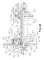
- the front hub 30 comprises a hub axle 40 nonrotatably fixed to the front fork 21, a hub shell 41 disposed around the outside of the hub axle 40, first and second bearings 42 and 43 disposed between the hub axle 40 and the hub shell 41, a detent member 44 for locking a first hub cone 72 of the first bearing 42 in relation to the hub axle 40, and a brake mount 45 for mounting the front disc rotor 25f.
- both ends of the hub axle 40 are fixed to both the left and right front forks 21 by a known quick release mechanism 60 having a hub rod 61 as well as a cam lever 62 and a nut 63 disposed at either end thereof.
- the hub axle 40 is made, for example, from an A7075 aluminum alloy with a high degree of strength, the hub rod 61 of the quick release mechanism 60 passes through the interior, and both ends are fixed to the tips of the front fork 21 by the quick release mechanism 60.
- the hub axle 40 has a hollow first spindle 46 and a hollow second spindle 47 screwed together with the first spindle 46.
- the first spindle 46 is an axle constituting a large portion of the hub axle 40.
- the bearings 42 and 43 are mounted at each end of the first spindle 46, with the second spindle 47 being screwed into one end (the left end in Figure 2A) of the first spindle 46.
- An external thread 46a is formed on the external peripheral surface of one end of the first spindle 46 for screwing the first hub cone 72 of the first bearing 42, and an internal thread 46bis formed on the internal peripheral surface of the same end for screwing in the second spindle 47.
- chamfers (not shown) disposed parallel to each other whereby the detent member 44 is nonrotatably locked are formed on the external peripheral surface of the one end.
- the first spindle 46 has a press-in part 46c with a second hub cone 75 of the second bearing 43 press-fitted thereon.
- An annular protrusion 46d is formed on the first spindle 46 adjacent to the press-in part 46c for positioning the second bearing 43.
- the protrusion 46d extends farther out in relation to the axial direction from the remainder of the first spindle 46.
- the press-in part 46c and the protrusion 46d are formed at the other end (the right end in Figure 2A) of the first spindle 46 from the second spindle 46.
- a small-diameter fork fixing part 46e fixed to the front fork 21 is also formed at the other end.
- a knurled part 46f is formed in the shape of radial irregularities at the end surface of the section in which a step is formed in relation to the fork fixing part 46e for rotatably locking with the front fork 21.
- the second spindle 47 is a cylindrical member with a smaller diameter than the first spindle 46.
- the second spindle 47 has an external thread 47a screwed into the internal thread 46b of the first spindle 46.
- the external thread 47a is formed on the external peripheral surface at the right end in Figure 2A.
- a small-diameter fork fixing part 47b is also formed at the left end for fixing to the front fork 21.
- a knurled part 47c is formed in the shape of radial irregularities at the end surface of the section in which a step is formed in relation to the fork fixing part 47b for rotatably locking with the front fork 21.
- a large-diameter flange 47d is formed between the external thread 47a and the fork fixing part 47b. The flange 47d is provided to retain the detent member 44.
- a tool locking part (not shown) with six sides to allow rotation by tools is formed on the internal peripheral surface at one end of the second spindle 47.
- the hub shell 41 is made, for example, from A6151 or another such lightweight aluminum alloy with a comparatively high degree of strength, and is a substantially symmetrical cylindrical member whose center section is narrowed down, as shown in Figure 2A.
- four first and second arms 51a and 51b that extend in a radial pattern and have substantially the same shape are formed on the external peripheral surface of the large-diameter section of the hub shell 41.
- a rotor attachment unit 52 is integrally formed on the tips of the first arms 51a.
- the rotor attachment unit 52 is preferably made of a plurality of individual attachment points or members that have a shape of a round bar extending farther out in relation to the direction of the hub axle 40.
- the first arms 51a and second arms 51b have substantially the same shape, with the exception of the rotor attachment unit 52 formed on the free ends of the first arms 51.
- the first arms 51 a and the rotor attachment unit 52 constitute the brake mount 45.
- Two spoke attachment holes 51c and 51d are formed at spaced intervals in the radial direction on the side surface in the direction of rotation in the middle of the first and second arms 51a and 51 b.
- the nipples 22d are secured in the spoke attachment holes 51c and 51d.
- the spoke attachment holes 51c and 51d are formed at a slight slant in the radial direction away from a tangent to an arc about the hub axle 40.
- the two attachment holes 51c and 51d are inclined in opposite directions, such that the spokes 22b extend in different directions.
- the spoke attachment holes 51 c and 51d are inclined in opposite directions in the first arms 51a and the second arms 51b. Therefore, of the two groups of spokes 22b drawn in alignment in Figure 4, the hatched spokes are alternately locked by the spoke attachment holes 51 c and 51d of the first arms 51a, while the remaining spokes are alternately locked by the spoke attachment holes 51c and 51d of the second arms 51b.
- Cover members 70a and 70b made from a synthetic resin, for example, for covering gaps with the hub axle 40 are detachably mounted on the two ends of the hub shell 41.
- the first bearing 42 has a first socket 71 provided to the hub shell 41, a first hub cone 72 screwed onto the hub axle 40, and a plurality of balls 73 that roll between the first hub cone 72 and the first socket 71 while in contact with both.
- Serrations 72a comprising a plurality of concavities and convexities formed in alignment in the circumferential direction are formed on the external peripheral surface of the first hub cone 72, and the detent member 44 engages these serrations 72a to rotatably lock the first hub cone 72.
- the second bearing 43 has a second socket 74 provided to the hub shell 41, a second hub cone 75 fixed to the hub axle 40, and a plurality of balls 76 that roll between the second hub cone 75 and the second socket 74 while in contact with both.
- the second socket 74 is a member of the same shape and material as the first socket 71.
- the second hub cone 75 is press-fitted by the press-in part 46c of the first spindle 46 of the hub axle 40.
- the second hub cone 75 is positioned by the protrusion 46d.
- the detent member 44 is made, for example, from A6151 or another such lightweight aluminum alloy with a comparatively high degree of strength. As shown in Figure 2A, the detent member 44 is a cylindrical member having two internal peripheral surfaces with different diameters. The internal peripheral surface of the detent member 44 with the smaller diameter is nonrotatably linked to the first spindle 46, while the internal peripheral surface of the detent member 44 with the larger diameter is nonrotatably linked to the first hub cone 72. Since the detent member 44 is nonrotatably stopped with the hub axle 40 and the first hub cone 72, the first hub cone 72 can be rotatably locked in relation to the hub axle 40.
- the brake mount 45 has, for example, four first arms 51a with the rotor attachment unit 52 formed at the tips of the first arms 51a.
- An attachment surface 52a is formed on each of the first arms 51a by mechanical working so as to be disposed in the same plane at the tip of the rotor attachment unit 52.
- a threaded hole 52b is formed in the attachment surface 52a into which an attachment bolt 53 is threadedly inserted for attaching a disc rotor 25f.
- a centering part (not shown) is also formed in the attachment surface 52a for aligning the center of the disc rotor 25f with the center of the hub axle 40.
- the disc rotor 25f When the disc rotor 25f is mounted to the front hub 30, the disc rotor 25f is fixed to the front hub 30 by threadedly inserting the attachment bolts 53 into the threaded holes 52b in a state in which the disc rotor 25f is centered. Since the hub 30 is structured such that the first arms 51a with the spoke attachment holes 51c and 51d in the middle are provided to the side of the front hub 30, and the disc rotor 25f is mounted on the rotor attachment unit 52 integrally formed on the tips of the first arms 51a, the braking surface 28f and the rotor attachment unit 52 are kept in close proximity to each other. Therefore, it is possible to suppress deformation in the disc rotor 25f even while reducing the thickness of the disc rotor 25f to lighten the weight, and it is also possible to suppress wobbling of the disc rotor 25f.
- a disc rotor 25r is also mounted in the same structure on the rear hub 31 equipped with a freewheel FR.
- first and second arms 51a and 51b are also formed on the rear hub 31, and a rotor attachment unit 52 is integrally formed on the tips of the first arms 51a.
- These components constitute a brake mount 45 for fixing the disc rotor 25r on the rear hub 31.
- first and second arms 51a and 51b are provided to the hub shell 41.
- fewer or more arms can be used as needed and/or desired.
- a front hub 130 is provided with a hub shell 141 that has five equally spaced apart first and second arms 151a with a brake mount 145 having a rotor attachment unit 152 (a plurality of attachment members) formed at the free ends of the first arms 151a.
- the remaining structure of the front hub 130 is the same as the front hub 30.
- the front hub 130 will not be discussed or illustrated in detail herein.
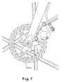
- a front hub 230 has a pair of hub flanges 354 (only the first flange is shown in Figure 8) with one of the hub flange 254 having a plurality (three) of equally spaced apart arms 252a.
- the remaining structure of the front hub 230 is the same as the front hub 30.
- the front hub 230 will not be discussed or illustrated in detail herein.
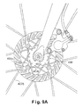
- a front hub 330 has a pair of hub flanges 354 (only the first flange is shown in Figure 8) with one of the hub flange 354 having a plurality of arms 351a.
- the hub flanges 354 are formed on the large-diameter sections of the hub shell with diameters that are greater than in other sections.
- the hub flange on the other side of hub shell in this embodiment does not have any arms.
- Each of the hub flanges 354 has spoke attachment points or holes 351a that are formed at spaced intervals in the circumferential direction on the hub flanges 354.
- the spokes 322b in this embodiment are disposed in a radial pattern in the radial direction.
- the spoke wires of the spokes 322b are locked in the spoke attachment parts or holes 351c.
- the number of arms should be between two and ten in this embodiment.
- a front hub 430 has a pair of hub flanges 454 with one of the hub flange 454 having a plurality of arms 451a.
- the hub flanges 454 are formed on the large-diameter sections of the hub shell with diameters that are greater than in other sections.
- the hub flange 454 on the other side of hub shell in this embodiment does not have any arms.
- Each of the hub flanges 454 has spoke attachment points or holes 451a that are formed at spaced intervals in the circumferential direction on the hub flanges 454.
- the spokes 422b in this embodiment are slanted in relation to the radial direction, which is the same as the usual arrangement.
- the spoke wires of the spokes 422b are locked in the spoke attachment parts or holes 451c.
- the number of arms should be between two and ten in this embodiment.
- the present invention was applied to a front hub in the embodiment previously described with reference to Figures 5-9B, but the present invention can also be applied to a rear hub having the same mounting structures of Figures 5-9B as described above.
- the configuration of the hub is not limited to the embodiment previously described, and particularly the configuration of the hub shell need not have a unitary construction and may have any kind of shape, such as a segmented structure configured from a plurality of members.
- the interior of the hub may comprise a brake adjusting mechanism, a power generating mechanism, or a speed shifting mechanism.
- the following directional terms "forward, rearward, above, downward, vertical, horizontal, below and transverse” as well as any other similar directional terms refer to those directions of a bicycle equipped with the present invention. Accordingly, these terms, as utilized to describe the present invention should be interpreted relative to a bicycle equipped with the present invention.
- the terms of degree such as “substantially”, “about” and “approximately” as used herein mean a reasonable amount of deviation of the modified term such that the end result is not significantly changed. These terms should be construed as including a deviation of at least ⁇ 5% of the modified term if this deviation would not negate the meaning of the word it modifies.
Landscapes
- Engineering & Computer Science (AREA)
- Mechanical Engineering (AREA)
- General Engineering & Computer Science (AREA)
- Braking Arrangements (AREA)
Applications Claiming Priority (2)
| Application Number | Priority Date | Filing Date | Title |
|---|---|---|---|
| JP2003002753A JP3732182B2 (ja) | 2003-01-09 | 2003-01-09 | 自転車用ハブ |
| JP2003002753 | 2003-01-09 |
Publications (2)
| Publication Number | Publication Date |
|---|---|
| EP1437235A2 true EP1437235A2 (fr) | 2004-07-14 |
| EP1437235A3 EP1437235A3 (fr) | 2005-04-06 |
Family
ID=32501219
Family Applications (1)
| Application Number | Title | Priority Date | Filing Date |
|---|---|---|---|
| EP04000350A Withdrawn EP1437235A3 (fr) | 2003-01-09 | 2004-01-09 | Moyeu de bicyclette |
Country Status (5)
| Country | Link |
|---|---|
| US (1) | US7066556B2 (fr) |
| EP (1) | EP1437235A3 (fr) |
| JP (1) | JP3732182B2 (fr) |
| CN (1) | CN1521019A (fr) |
| TW (1) | TWI228082B (fr) |
Cited By (6)
| Publication number | Priority date | Publication date | Assignee | Title |
|---|---|---|---|---|
| EP1953007A1 (fr) * | 2007-02-01 | 2008-08-06 | Shimano Inc. | Structure de fixation de roue de bicyclette |
| EP1953008A1 (fr) * | 2007-02-01 | 2008-08-06 | Shimano Inc. | Structure de fixation de roue de bicyclette |
| EP1894743A3 (fr) * | 2006-08-31 | 2009-04-29 | DT Swiss AG | Moyeu et roue de roulement, en particulier pour vélos |
| US7874625B2 (en) | 2008-09-04 | 2011-01-25 | Trek Bicycle Corporation | Bicycle wheel assembly having dissimilar lateral spoke lacings |
| DE102008026700B4 (de) * | 2007-06-19 | 2011-05-12 | Shimano Inc., Sakai | Fahrradlaufrad-Befestigungsstruktur |
| US9457868B2 (en) | 2014-08-06 | 2016-10-04 | Shimano Inc. | Bicycle hydraulic quick-release apparatus and bicycle frame |
Families Citing this family (26)
| Publication number | Priority date | Publication date | Assignee | Title |
|---|---|---|---|---|
| JP3732166B2 (ja) * | 2002-08-22 | 2006-01-05 | 株式会社シマノ | 自転車用ハブ |
| JP2006029552A (ja) * | 2004-07-21 | 2006-02-02 | Shimano Inc | 自転車用ディスクロータ |
| DE102004063505A1 (de) * | 2004-12-26 | 2006-07-06 | Nicolai, Karlheinz, Dipl.-Ing. (TU) | Hinterrad und Hinterradnabe für Fahrräder |
| US7284643B1 (en) * | 2006-07-28 | 2007-10-23 | Ching-Wen Kao | Brake disk |
| US7673946B1 (en) * | 2006-09-21 | 2010-03-09 | Hed Cycling Products, Inc. | Hub apparatus for bicycle wheel and method |
| US7837213B2 (en) * | 2007-04-16 | 2010-11-23 | Trek Bicycle Corporation | Bicycle rear wheel suspension system |
| JP2009161015A (ja) * | 2007-12-28 | 2009-07-23 | Yamaha Motor Co Ltd | 自動二輪車のフロントフェンダ、及び自動二輪車 |
| DE102008013938A1 (de) * | 2008-03-12 | 2009-09-17 | Dt Swiss Ag | Fahrradkomponente |
| US7854286B2 (en) * | 2008-10-21 | 2010-12-21 | Honda Motor Company, Ltd. | Motorcycle having concealed brake caliper |
| JP2011201398A (ja) * | 2010-03-25 | 2011-10-13 | Honda Motor Co Ltd | 自動二輪車のホイール |
| JP5435808B2 (ja) * | 2010-11-01 | 2014-03-05 | 本田技研工業株式会社 | ハブの製造方法および該ハブを備えるホイール |
| JP5665646B2 (ja) * | 2011-04-28 | 2015-02-04 | 本田技研工業株式会社 | 車両のホイール |
| JP5803739B2 (ja) * | 2012-02-28 | 2015-11-04 | サンスター技研株式会社 | ブレーキディスク |
| JP5990045B2 (ja) * | 2012-06-26 | 2016-09-07 | 本田技研工業株式会社 | 鞍乗り型車両 |
| ITUB20154195A1 (it) | 2015-10-07 | 2017-04-07 | Campagnolo Srl | Componente di ruota di bicicletta con zona di frenatura in materiale composito e relativo procedimento di fabbricazione |
| ITUB20156263A1 (it) * | 2015-12-03 | 2017-06-03 | Campagnolo Srl | Mozzo per una ruota di bicicletta |
| KR102429006B1 (ko) * | 2016-12-07 | 2022-08-03 | 현대자동차 주식회사 | 브레이크 디스크를 갖는 허브유닛 |
| JP6439024B1 (ja) * | 2017-10-27 | 2018-12-19 | 株式会社シマノ | 自転車用ハブユニットおよび自転車用ホイールアセンブリ |
| JP6586486B1 (ja) * | 2018-05-30 | 2019-10-02 | 啓元 菊地 | ホイール |
| JP6759305B2 (ja) * | 2018-11-15 | 2020-09-23 | 株式会社シマノ | 自転車用ハブユニットおよび自転車用ホイールアセンブリ |
| US11260691B2 (en) * | 2019-02-11 | 2022-03-01 | Two Point Zero Usa, Inc. | Interchangeable hub system for bicycle |
| TWI801651B (zh) * | 2019-08-21 | 2023-05-11 | 菊地啓元 | 輪圈 |
| WO2021053739A1 (fr) * | 2019-09-18 | 2021-03-25 | 啓元 菊地 | Procédé de fabrication de roue |
| CN214985873U (zh) * | 2021-02-07 | 2021-12-03 | 深圳市美大行科技有限公司 | 碟刹装置及自行车 |
| DE102021208800A1 (de) * | 2021-08-11 | 2023-02-16 | Klaus Wohlfarth | Felgensystem und Anordnung mit einem Felgensystem |
| DE202022103386U1 (de) * | 2022-06-15 | 2023-09-18 | Zeg Zweirad-Einkaufs-Genossenschaft Eg | Nabe für Laufräder von Fahrrädern mit Scheibenbremsen, und Laufrad hiermit |
Citations (1)
| Publication number | Priority date | Publication date | Assignee | Title |
|---|---|---|---|---|
| JP2001246904A (ja) | 2000-01-31 | 2001-09-11 | Shimano Inc | ディスクブレーキ用自転車ハブ |
Family Cites Families (17)
| Publication number | Priority date | Publication date | Assignee | Title |
|---|---|---|---|---|
| US2290451A (en) * | 1939-08-02 | 1942-07-21 | Frank W Schwinn | Bicycle hub and method of making it |
| US3985391A (en) * | 1975-08-21 | 1976-10-12 | Brake Engineering, Inc. | Disc brake apparatus suitable for bicycles |
| US4170369A (en) * | 1978-01-23 | 1979-10-09 | Lauren Strutman | Bicycle wheel suspension, driving and braking assembly |
| JPH04328001A (ja) | 1991-04-26 | 1992-11-17 | Suzuki Motor Corp | 組立式ホイールハブ |
| JPH05221202A (ja) | 1992-02-14 | 1993-08-31 | Suzuki Motor Corp | 自動二輪車の後輪ハブ |
| US5626401A (en) * | 1994-05-17 | 1997-05-06 | Innovative Bicycle Components Company | Spoked wheel hub |
| US5950772A (en) * | 1997-08-29 | 1999-09-14 | Hayes Brake, Inc. | Bicycle brake system having a flexible disk |
| JP3969552B2 (ja) | 1998-05-12 | 2007-09-05 | ヤマハ発動機株式会社 | 自動二輪車の後輪用ホイール |
| FR2783491B1 (fr) | 1998-09-17 | 2000-12-15 | Mavic Sa | Frein a disque a commande mecanique pour bicyclette et roue equipe d'un tel frein a disque |
| DE19915714A1 (de) * | 1999-04-08 | 2000-10-12 | Sram De Gmbh | Nabe für Fahrräder |
| FR2794063B1 (fr) | 1999-05-28 | 2001-07-27 | Mavic Sa | Moyeu de roue de bicyclette prevu pour etre equipe d'un disque de freinage |
| DE19926641C5 (de) | 1999-06-11 | 2010-04-08 | Sram Deutschland Gmbh | Nabe für ein Laufrad |
| US6354669B1 (en) * | 2000-01-31 | 2002-03-12 | Shimano Inc. | Bicycle hub for tangential spokes |
| US6318810B1 (en) * | 2000-03-06 | 2001-11-20 | Frank T. Miyake | Motorcycle modular carrier ring |
| US6336531B1 (en) * | 2000-03-15 | 2002-01-08 | Tzu-Chieh Chou | Braking disc assembly |
| US6540306B2 (en) * | 2001-06-29 | 2003-04-01 | Shimano Inc. | Bicycle disc brake hub |
| CA2415809A1 (fr) * | 2002-01-09 | 2003-07-09 | First Principles Engineering Inc. | Adaptateur de moyeu pour frein a disque de bicyclette |
-
2003
- 2003-01-09 JP JP2003002753A patent/JP3732182B2/ja not_active Expired - Fee Related
- 2003-12-19 TW TW092136267A patent/TWI228082B/zh not_active IP Right Cessation
- 2003-12-29 US US10/745,617 patent/US7066556B2/en not_active Expired - Fee Related
-
2004
- 2004-01-08 CN CNA2004100014833A patent/CN1521019A/zh active Pending
- 2004-01-09 EP EP04000350A patent/EP1437235A3/fr not_active Withdrawn
Patent Citations (1)
| Publication number | Priority date | Publication date | Assignee | Title |
|---|---|---|---|---|
| JP2001246904A (ja) | 2000-01-31 | 2001-09-11 | Shimano Inc | ディスクブレーキ用自転車ハブ |
Cited By (8)
| Publication number | Priority date | Publication date | Assignee | Title |
|---|---|---|---|---|
| EP1894743A3 (fr) * | 2006-08-31 | 2009-04-29 | DT Swiss AG | Moyeu et roue de roulement, en particulier pour vélos |
| EP1953007A1 (fr) * | 2007-02-01 | 2008-08-06 | Shimano Inc. | Structure de fixation de roue de bicyclette |
| EP1953008A1 (fr) * | 2007-02-01 | 2008-08-06 | Shimano Inc. | Structure de fixation de roue de bicyclette |
| US7537291B2 (en) | 2007-02-01 | 2009-05-26 | Shimano Inc. | Bicycle wheel securing structure |
| DE102008026700B4 (de) * | 2007-06-19 | 2011-05-12 | Shimano Inc., Sakai | Fahrradlaufrad-Befestigungsstruktur |
| US7874625B2 (en) | 2008-09-04 | 2011-01-25 | Trek Bicycle Corporation | Bicycle wheel assembly having dissimilar lateral spoke lacings |
| US9457868B2 (en) | 2014-08-06 | 2016-10-04 | Shimano Inc. | Bicycle hydraulic quick-release apparatus and bicycle frame |
| DE102015010190B4 (de) * | 2014-08-06 | 2025-07-10 | Shimano Inc. | Hydraulischer Schnellauslöseapparat für Fahrrad und Fahrradrahmen |
Also Published As
| Publication number | Publication date |
|---|---|
| CN1521019A (zh) | 2004-08-18 |
| US20040135425A1 (en) | 2004-07-15 |
| JP3732182B2 (ja) | 2006-01-05 |
| US7066556B2 (en) | 2006-06-27 |
| JP2004210242A (ja) | 2004-07-29 |
| TWI228082B (en) | 2005-02-21 |
| TW200416151A (en) | 2004-09-01 |
| EP1437235A3 (fr) | 2005-04-06 |
Similar Documents
| Publication | Publication Date | Title |
|---|---|---|
| EP1437235A2 (fr) | Moyeu de bicyclette | |
| EP1495879B1 (fr) | Moyeu de bicyclette extérieur et moyeu de bicyclette | |
| US11097807B2 (en) | Bicycle hub assembly | |
| US10005520B2 (en) | Bicycle driving system and a multiple rear sprocket assembly thereof | |
| USRE42986E1 (en) | Bicycle disc brake hub | |
| EP1213217B2 (fr) | Moyeu de bicyclette | |
| EP1820666B1 (fr) | Moyeu de frein à disque pour bicyclette | |
| US6886894B2 (en) | Bicycle hub axle | |
| US6409282B1 (en) | Bicycle hub | |
| US20080004143A1 (en) | Bicycle sprocket assembly | |
| US9855794B1 (en) | Bicycle hub assembly | |
| US20110130233A1 (en) | Bicycle sprocket support assembly | |
| JP2008254728A (ja) | 自転車用シャフト部品 | |
| US6540306B2 (en) | Bicycle disc brake hub | |
| US7288865B2 (en) | Bicycle generator hub | |
| US7374251B2 (en) | Connection of Spokes to hub and rim in bicycle wheel | |
| US6485108B1 (en) | Bicycle hub | |
| EP1780049B1 (fr) | Moyeu de bicyclette |
Legal Events
| Date | Code | Title | Description |
|---|---|---|---|
| PUAI | Public reference made under article 153(3) epc to a published international application that has entered the european phase |
Free format text: ORIGINAL CODE: 0009012 |
|
| AK | Designated contracting states |
Kind code of ref document: A2 Designated state(s): AT BE BG CH CY CZ DE DK EE ES FI FR GB GR HU IE IT LI LU MC NL PT RO SE SI SK TR |
|
| AX | Request for extension of the european patent |
Extension state: AL LT LV MK |
|
| PUAL | Search report despatched |
Free format text: ORIGINAL CODE: 0009013 |
|
| AK | Designated contracting states |
Kind code of ref document: A3 Designated state(s): AT BE BG CH CY CZ DE DK EE ES FI FR GB GR HU IE IT LI LU MC NL PT RO SE SI SK TR |
|
| AX | Request for extension of the european patent |
Extension state: AL LT LV MK |
|
| 17P | Request for examination filed |
Effective date: 20050722 |
|
| AKX | Designation fees paid |
Designated state(s): AT BE BG CH CY CZ DE DK EE ES FI FR GB GR HU IE IT LI LU MC NL PT RO SE SI SK TR |
|
| RAP1 | Party data changed (applicant data changed or rights of an application transferred) |
Owner name: SHIMANO INC. |
|
| 17Q | First examination report despatched |
Effective date: 20070814 |
|
| STAA | Information on the status of an ep patent application or granted ep patent |
Free format text: STATUS: THE APPLICATION IS DEEMED TO BE WITHDRAWN |
|
| 18D | Application deemed to be withdrawn |
Effective date: 20071228 |