EP1437471A2 - Ferrure pour une porte à soulèvement et coulissement ou une fenêtre à soulèvement - Google Patents
Ferrure pour une porte à soulèvement et coulissement ou une fenêtre à soulèvement Download PDFInfo
- Publication number
- EP1437471A2 EP1437471A2 EP04000038A EP04000038A EP1437471A2 EP 1437471 A2 EP1437471 A2 EP 1437471A2 EP 04000038 A EP04000038 A EP 04000038A EP 04000038 A EP04000038 A EP 04000038A EP 1437471 A2 EP1437471 A2 EP 1437471A2
- Authority
- EP
- European Patent Office
- Prior art keywords
- running shoe
- groove
- coupling
- running
- sash
- Prior art date
- Legal status (The legal status is an assumption and is not a legal conclusion. Google has not performed a legal analysis and makes no representation as to the accuracy of the status listed.)
- Granted
Links
Images






Classifications
-
- E—FIXED CONSTRUCTIONS
- E05—LOCKS; KEYS; WINDOW OR DOOR FITTINGS; SAFES
- E05D—HINGES OR SUSPENSION DEVICES FOR DOORS, WINDOWS OR WINGS
- E05D15/00—Suspension arrangements for wings
- E05D15/56—Suspension arrangements for wings with successive different movements
- E05D15/565—Suspension arrangements for wings with successive different movements for raising wings before sliding
-
- E—FIXED CONSTRUCTIONS
- E05—LOCKS; KEYS; WINDOW OR DOOR FITTINGS; SAFES
- E05Y—INDEXING SCHEME ASSOCIATED WITH SUBCLASSES E05D AND E05F, RELATING TO CONSTRUCTION ELEMENTS, ELECTRIC CONTROL, POWER SUPPLY, POWER SIGNAL OR TRANSMISSION, USER INTERFACES, MOUNTING OR COUPLING, DETAILS, ACCESSORIES, AUXILIARY OPERATIONS NOT OTHERWISE PROVIDED FOR, APPLICATION THEREOF
- E05Y2800/00—Details, accessories and auxiliary operations not otherwise provided for
-
- E—FIXED CONSTRUCTIONS
- E05—LOCKS; KEYS; WINDOW OR DOOR FITTINGS; SAFES
- E05Y—INDEXING SCHEME ASSOCIATED WITH SUBCLASSES E05D AND E05F, RELATING TO CONSTRUCTION ELEMENTS, ELECTRIC CONTROL, POWER SUPPLY, POWER SIGNAL OR TRANSMISSION, USER INTERFACES, MOUNTING OR COUPLING, DETAILS, ACCESSORIES, AUXILIARY OPERATIONS NOT OTHERWISE PROVIDED FOR, APPLICATION THEREOF
- E05Y2900/00—Application of doors, windows, wings or fittings thereof
- E05Y2900/10—Application of doors, windows, wings or fittings thereof for buildings or parts thereof
- E05Y2900/13—Type of wing
- E05Y2900/132—Doors
-
- E—FIXED CONSTRUCTIONS
- E05—LOCKS; KEYS; WINDOW OR DOOR FITTINGS; SAFES
- E05Y—INDEXING SCHEME ASSOCIATED WITH SUBCLASSES E05D AND E05F, RELATING TO CONSTRUCTION ELEMENTS, ELECTRIC CONTROL, POWER SUPPLY, POWER SIGNAL OR TRANSMISSION, USER INTERFACES, MOUNTING OR COUPLING, DETAILS, ACCESSORIES, AUXILIARY OPERATIONS NOT OTHERWISE PROVIDED FOR, APPLICATION THEREOF
- E05Y2900/00—Application of doors, windows, wings or fittings thereof
- E05Y2900/10—Application of doors, windows, wings or fittings thereof for buildings or parts thereof
- E05Y2900/13—Type of wing
- E05Y2900/148—Windows
Definitions
- the invention relates to a fitting for lift-slide doors or windows according to the preamble of claim 1, 3 or 11 and on a lift and slide door or a lift and slide window according to the preamble of claim 13.
- Lifting and sliding doors or lifting and sliding windows as well as suitable fittings for these doors are well known.
- the basic function of such doors or windows is that the respective door or window wing relative to an outer floor frame can be raised and lowered and at the same time can also be moved in the wing plane, so that, for example, to open the closed wing, this first in is lifted in the vertical direction and then moved in the horizontal direction. In the wing is closed in the opposite way.
- you can lifting and sliding doors in particular also have a tilt function.
- a manually provide actuable gear (DE 78 16 563 U1), which is particularly for Raising and lowering using an espagnolette fitting or one on one Forced rail provided drive rod and with a corner drive with drive connected to the carriage or running shoes provided on the underside of the wing is.
- the gearbox When the gearbox is operated manually, the drive rod is moved and thereby the carriage or running shoe of the fitting relative to one at the bottom horizontal spar of the casement provided bearing element in Running shoe longitudinal direction moves. Via an inclined slot pin guide between the running shoe and the bearing element Change in distance between the running shoe and the lower horizontal spar of the Wing and thus the raising and lowering of the door wing relative to the outer Stick or frame.
- the vertical movement initially generated must be from one on a vertical side of the sash frame provided drive or push rod in a horizontal Movement can be implemented.
- this is done by a two-armed lever, also known as a bell lever and one Axis is pivotally mounted perpendicular to the plane of the wing, on one Bearing element of the fitting, which in the fold of the sash at the corner area between the vertical and the lower horizontal spar or section of the casement is assembled.
- Fittings are also known in which the corner deflection consists of several spring steel strips arranged one above the other in a lamella-like manner (DE 34 40 505) or is formed by a chain (DE 72 44 800). These versions have the Disadvantage that the transmission of thrust or pressure forces is insufficient is and therefore the lowering movement of the door leaf by the weight this wing must at least be supported. The latter inter alia affects the free Design possibility of between the running shoe and the associated one Bearing element acting stroke curve.
- the object of the invention is to show a fitting (connecting rod fitting) can be manufactured particularly inexpensively with a reliable working method and also allows a reduction in the width and / or depth of the installation groove.
- a rigid, rod-like or pressure and tensile coupling piece formed, which is slidably guided in the bearing element.
- a bell-like, two-armed lever and the associated disadvantages, especially one additional manufacturing costs and a relatively large amount of space when Installation are avoided. Due to the rod-like or push and pull-like Training of the coupling piece, this is capable of both tensile forces and Reliably transfer pressure forces to the running shoe.
- the faceplate is one Fitting for lift-slide doors or windows designed flat or flat band-like.
- Figure 1 shows a building door, which in a known manner from the floor or Frame 1 and consists of the door leaf 2 provided in this frame, designed as a lift and slide sash, for example, with an additional tilt function is, i.e. to open and close in the vertical direction raised or lowered can be moved and tilted.
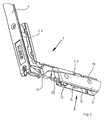
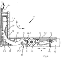
- the bearing element 7 is on the leg 7.1, which in the assembled state of the Fitting 3 is oriented in the vertical direction, connected to the faceplate 4, for example by screwing or riveting.
- Another leg 7.2 of the Bearing element 7, the 3 when mounted on the lower horizontal spar of Door frame 2.1 is provided, the bearing for the housing 8 forms one Running shoe 9.
- the housing 8 is in the embodiment shown in one piece from one suitable material, e.g. metal, e.g. as a metal injection molded part (Zinc injection molding) made, with two in the longitudinal direction of the running shoe 2 extending parallel housing walls 10, which at the two ends of the Housing are connected to each other by corresponding walls 11. Between the two ends are the walls 10 by additional stiffening walls 11.1 connected with each other.
- suitable material e.g. metal, e.g. as a metal injection molded part (Zinc injection molding) made, with two in the longitudinal direction of the running shoe 2 extending parallel housing walls 10, which at the two ends of the Housing are connected to each other by corresponding walls 11. Between the two ends are the walls 10 by additional stiffening walls 11.1 connected with each other.
- two rollers 12 are free in the housing 8 rotatably mounted, namely about axes perpendicular to the plane of the door leaf 2.
- Die Rollers 12 are in a known manner with one on the lower element of the Floor frame 1 provided track 13 in engagement, for example, also is made of metal.
- a coupling piece 17 is provided, which is rigid as a push and pull piece executed and formed in the illustrated embodiment as part of a ring is.
- a circular arc Guide formed, in such a way that the coupling piece 17 in this guide an arc is movable about an axis perpendicular to the plane of the door leaf (Double arrow K).
- the coupling piece 17 is on its outer, i.e. convex curved side with a plurality of teeth 20 forming a toothing. This toothing engages in openings 6.1 at the lower end of the drive rod 6, so that the axial movement of the drive rod 6 (double arrow V), the coupling piece 17th according to the double arrow K, a longitudinal movement in the form of a circular movement performs.
- the end of the coupling piece 17 which is distant from the teeth 20 is articulated with connected to this coupling piece end of the running shoe 6, and in that the end in question with a hook-like section 21 in a Opening 22.1 of an eyelet section 22 provided on the end wall 11 engages.
- the coupling piece 17 engages with its Section 21 from above into the recess 22.1 of the eyelet section 22 and engages behind an edge of the eyelet section 22 with one on the section 21 formed rounded surface 21.1.
- the training continues to be such that section 21 on two in an axial direction perpendicular to the wing plane or parallel to the axis of rotation of the rollers 12 against each other offset side surfaces Areas is guided within the recess 22.1, whereby the movements of the Coupling piece 17 and the running shoe 9 when lifting and lowering the Door wing 2 are stabilized.
- the axis of the circular arc movement lies of the coupling piece 17 within that formed by the legs 7.1 and 7.2 Angular space, perpendicular to a plane that is from the longitudinal axes of this Leg is defined.
- the fitting 3 shown avoids the lifting and Sliding fittings usual swiveling deflection bell. This results in a very simple and reliable construction.
- the coupling piece 17 at one end is one reliable drive connection between the drive rod 6 and the Coupling piece 17 and the running shoe 9 guaranteed, namely a drive connection, via which both tensile forces for lifting the door leaf, as well as thrust forces for lowering the door leaf 2 are effectively transmitted can.
- Another advantage of the redirection using the coupling piece 17 is that the bearing element 7 is very much in the region of this deflection can be made small-volume, which is required for installation in the door leaf 2 So space is kept small.
- FIG. 1 is on the lower, horizontal portion of the Sash frame 2.1 on a further bearing element 23 is another running shoe 24 provided, in the region of the second one which is remote from the bearing element 7 lower corner of the casement 2.1.
- the bearing element 23 is similar to the leg 7.2 of the bearing element 7 is formed.
- the running shoe 24 corresponds to the running shoe 9.
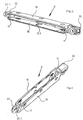
- Both running shoes 9 and 24 are in a known manner via a connecting link 25 interconnected, which is suitable for the transmission of compressive and tensile forces is.
- This connecting link 25 is, for example, a connecting rod that is connected to their ends are attached to the running shoes 9 and 24 by engaging in sleeve-like coupling or connecting sections 26, which on the respective Running shoe housing 8 or 8a at the end, i.e. molded in the area of the end wall 11 are.
- the running shoe housing 8a of the running shoe 24 differs from Running shoe housing 8 only in that on both end walls 11 of the Running shoe housing 8a there is a coupling section 26.
- FIG. 7 shows the installed state of the bearing element 7 or of the leg 7.2. This is together with the running shoe 9 in one on the underside of the door leaf provided groove 27 added. Both sides of the groove are on the bottom of the Door wing two each extending over the entire width of this door wing Seals 28 are provided which, when lowered, i.e. closed door leaf 2 bear against a sealing surface 13.1 of the running rail 13.
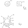
- FIG. 8 shows a connection 25 or connecting rod 25.1 in cross section circular cross section and a connecting rod 25.2 with square Cross section, which can be used optionally as connection 25.
- the cross sections of the two connecting rods are coordinated so that the diagnostics of the Cross section of the square connecting rod 25.2 is slightly larger than that Diameter or twice the radius of the cross-section of the connecting rod 25.1.
- Coupling section 26 has an opening 29, the cross-sectional shape of which is initially a square cross-section corresponds, combined with a circular Cross section in such a way that each of the four sides of the cross section each correspond to the circular cross-section corresponding circular cylindrical curved area 30 and these areas 30, which around the common central axis of the Sleeve opening 29 are curved, are formed such that the corner regions 31 of the square cross-section, i.e. there at right angles to each other Areas are available. This means that the radius of curvature of the curved Areas 30 in turn is smaller than half the distance between two diagonally opposite corner areas 31.
- connecting rods 25.1 and 25.2 can be obtained inexpensively on the market Bar profiles made of metal, for example made of steel, can be used.
- the Overall cross section of these connecting rods can be kept relatively small, because the respective connection 25 or connecting rod 25.1 or 25.2 is essentially only under tension. This results from the training of the lifting curves 16 on the bearing elements 7 and 23.
- the longitudinal extent of the the respective stroke curve closes with the horizontal (axial direction of the double arrow H) an acute angle ⁇ , i.e. an angle ⁇ less than 90 ° (Fig. 4), which at the running shoe 9 to the corner deflection 7 and in the running shoe 24 from the running shoe 9 opens.
- This course of the stroke curve results in the tensile load in the Connection 25 due to the weight of the door leaf 3. Compressive forces occur in this Connection not on.
- 101 denotes a building door, which in turn is one outer stick or frame 102, a provided in this frame Fixed field 103 with the associated frame 104 and the associated glazing 105 and has a wing 106 which is designed as a lifting and sliding wing.
- the wing 106 in turn consists of the wing frame 107, which the glazing 108th and four of them adjoining each other at right angles Casement elements made of a casement profile e.g. is made of wood, namely from the lower, horizontal casement element 107.1, which the Opening or gear side of the wing 106 forming vertical Sash element 107.2, the upper horizontal sash element 107.3 and the further vertical casement element 107.4.
- Casement elements made of a casement profile e.g. is made of wood, namely from the lower, horizontal casement element 107.1, which the Opening or gear side of the wing 106 forming vertical Sash element 107.2, the upper horizontal sash element 107.3 and the further vertical casement element 107.4.
- Gear 110 is provided, with which via a in the fold of the sash 107th provided connecting rod fitting, among other things locking or unlocking the in the closed position of moving wing 106 also on the frame 102 as well the raising and lowering of the wing 106 for opening or closing possible is.
- the wing 106 can be parallel to the raised state its wing plane or parallel to the plane of the fixed field 103 in the horizontal direction be moved.
- This is at the bottom in the illustrated embodiment horizontal casement element 107.1 two running shoes or carriage 111 provided that only schematically in Figure 10 with their carriage rollers 112 are indicated and with these rollers 112 in a horizontal guide rail are led.
- the two carriages are for lifting and lowering the wing 106 111 with corresponding lifting means which can be actuated via the connecting rod fitting educated.
- FIG 11 shows a simplified representation of the lower, horizontal Sash frame element 107.1 for a sash frame 107 made of wood.
- this Sash frame element is i.a. a groove 113 is introduced on the underside, which for Underside of the sash element 107.1 is open and in the illustrated Embodiment with its central plane in the vertical central plane of the Sash element 107.1 lies.
- the groove 113 serves to receive the carriage 111, in this groove in the longitudinal direction of the sash element 107.1 against offset from each other, but for raising and lowering the wing 106 are connected to each other in terms of drive.
- Each carriage 111 is with one Carriage carrier 114 on the bottom 113.1 of the groove 113 in a suitable manner, for example fixed by screwing.
- the carriage rollers 112 are on a carriage or Running shoe housing 115 freely rotatable.
- the carriage housing 115 is for the raising and lowering of the wing 106 with the carriage carrier over the Lifting means connected, which in the simplest case from a lifting curve on Carriage carrier 114 and one interacting with this stroke curve Guide or slide bolts are formed on the carriage housing 115.
- the depth of the groove 113 is selected so that at least when the wing 106 is lowered Carriage 111 with all of its elements, including its carriage rollers 112 are almost completely accommodated in the groove 113.
- On its open side is the Slightly widened groove 113, i.e. provided on both sides with a recess 116 so that each side surface 113.2 of the groove in the area of these recesses with one step each forms a surface 113.3 which is in a plane perpendicular to the central plane of the groove 113 lies.
- FIG. 12 shows a section through the vertical casement element 107.2 of the sash frame 107 made of wood. Also in the sash element 107.2 is on the fold or on the frame 102 when the sash 106 is closed the groove 113 in turn adjacent the outer side of the casement 107 with the two recesses 116 and with the additional grooves 117 for the Seals introduced.
- the groove 113 is used here for fastening the faceplate 118 of the drive rod fitting already mentioned.
- the faceplate 118 is a flat, band-like or strip-like (flat-band-like) rail formed and suitable Fasteners 119 anchored in the groove 113, in such a way that the Face plate 118 on its side facing the groove 113 in an edge region of its Long sides abuts against the surfaces 113.3 formed by the recesses 116 and covers the groove 113 to the outside.
- Within the groove 113 is on the Face plate 118 in the longitudinal direction also has a flat band-like drive rod 120 slidably guided.
- the drive rod 120 is driven by the gear 110 connected and controls about a corner drive, not shown, as they
- the carriage is known to the person skilled in the art from DE 203 04 001 U. 111 for raising and lowering the wing 106.
- the flat band-like design of the faceplate 118 has i.a. in addition to one Material and cost savings in particular also the advantage that the groove 113th at least outside the recesses 116, i.e. over the greater part of their depth can be made relatively narrow, i.e. the groove width from the currently usual Width can be reduced from about 22 mm to about 16 mm, which is the same external dimensions of the wooden profile used for the casement 107 a significant increase in the strength of the sash 107 and thus u. a too increases the security against burglary, or a more compact design, especially by reducing the dimensions of the sash 107 profile used.
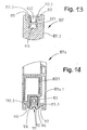
- Figure 13 shows a section through the upper, horizontal casement element.
- the groove 113 with the two cutouts 116 is again provided there, namely together with the grooves 117 provided on both sides by the groove 113 for the seal.
- An H-shaped profile is in the groove 113 on the casement element 107.3 121 used and fastened in a suitable manner.
- the profile 121 is resilient a guide piece 122 attached in one piece, with which the wing 106 on its Top, i.e. with its sash element 107.3 on the frame 102 for the Raising and lowering and for moving is performed.
- the groove 113 there which is necessary for receiving the functional elements, is identical trained, which is also a significant simplification and cost savings in the Manufacturing means that the same tools for the grooves 113 on all Sash frame elements 107.1, 107.2 and 107.3 can be used.
- each groove 117 on one Sash frame element 107.1 - 107.3 in a common plane with the corresponding groove on the other casement elements so that in the Grooves 117 of the sash elements 107.1 - 107.2 received seals as continuous seals can be made and thus an optimal Sealing is achieved with the wing 106 closed.
- Figures 14-16 show sections similar to Figures 12-13, but in one Sash frame 107a, the sash frame elements 107a.1, 107a.2 and 107a.3 each of a multi-chamber plastic profile with an internal metal reinforcement 123 are formed. Also in this embodiment is in all Sash frame elements 107a.1, 107a.2 and 107a.3 in turn the groove 113 with the two recesses 116 and with the recesses formed by these Contact surfaces 113.3 and provided with the additional grooves 117.
- At the Sash frame element 107a.1 in turn serves essentially for Inclusion of the two carriages 111 for the sash element 107a.2 Recording and fastening the flat band-like faceplate 118 with the drive rod 118 and with the sash frame element 107a.3 for receiving the H-profile 121 with the Guide piece 122.
Landscapes
- Engineering & Computer Science (AREA)
- Mechanical Engineering (AREA)
- Power-Operated Mechanisms For Wings (AREA)
- Wing Frames And Configurations (AREA)
Applications Claiming Priority (6)
| Application Number | Priority Date | Filing Date | Title |
|---|---|---|---|
| DE20300403 | 2003-01-10 | ||
| DE20300403U | 2003-01-10 | ||
| DE20304001U | 2003-03-13 | ||
| DE20304001U DE20304001U1 (de) | 2003-01-10 | 2003-03-13 | Beschlag für Hebe-Schiebe-Türen oder -Fenster sowie Laufschuh für einen solchen Beschlag |
| DE20313145U | 2003-08-22 | ||
| DE20313145U DE20313145U1 (de) | 2003-08-22 | 2003-08-22 | Hebe-Schiebe-Tür oder -Fenster sowie Treibstangenbeschlag für Hebe-Schiebe-Türen oder -Fenster |
Publications (3)
| Publication Number | Publication Date |
|---|---|
| EP1437471A2 true EP1437471A2 (fr) | 2004-07-14 |
| EP1437471A3 EP1437471A3 (fr) | 2005-01-12 |
| EP1437471B1 EP1437471B1 (fr) | 2008-12-24 |
Family
ID=32511974
Family Applications (1)
| Application Number | Title | Priority Date | Filing Date |
|---|---|---|---|
| EP04000038A Expired - Lifetime EP1437471B1 (fr) | 2003-01-10 | 2004-01-03 | Ferrure pour une porte à soulèvement et coulissement ou une fenêtre à soulèvement |
Country Status (2)
| Country | Link |
|---|---|
| US (1) | US20040163317A1 (fr) |
| EP (1) | EP1437471B1 (fr) |
Cited By (7)
| Publication number | Priority date | Publication date | Assignee | Title |
|---|---|---|---|---|
| US8240089B2 (en) | 2007-12-21 | 2012-08-14 | Gsg International S.P.A. | Carriage for sliding doors and windows |
| CN102704802A (zh) * | 2012-06-04 | 2012-10-03 | 长治市生华商贸有限公司 | 扇梃焊接的新型单扇推拉密封窗及其制作方法 |
| EP2712994A1 (fr) | 2012-09-26 | 2014-04-02 | GSG INTERNATIONAL S.p.A. | Unité de chariot pour porte ou fenêtre coulissante du type levant et coulissant |
| EP2712990A1 (fr) | 2012-09-26 | 2014-04-02 | GSG INTERNATIONAL S.p.A. | Ensemble de chariot du type levage et coulissement pour une porte ou fenêtre coulissante |
| EP2712991A1 (fr) | 2012-09-26 | 2014-04-02 | GSG INTERNATIONAL S.p.A. | Unité de chariot pour porte ou fenêtre coulissante du type levant et coulissant |
| WO2016050389A1 (fr) * | 2014-09-29 | 2016-04-07 | Maco Technologie Gmbh | Renvoi d'angle |
| WO2019243195A1 (fr) * | 2018-06-21 | 2019-12-26 | Maco Technologie Gmbh | Agencement de ferrure |
Families Citing this family (23)
| Publication number | Priority date | Publication date | Assignee | Title |
|---|---|---|---|---|
| KR100721455B1 (ko) * | 2005-12-21 | 2007-05-23 | 주식회사 엘지화학 | 시스템창호 개폐장치 |
| EP1891292B1 (fr) * | 2005-12-21 | 2014-07-30 | LG Chem, Ltd. | Dispositif d'ouverture/fermeture pour portes et fenetres coulissantes a systeme de levage |
| US20070271850A1 (en) * | 2006-05-02 | 2007-11-29 | Brad Mickelson | Self-contained motorized lift-slide panel |
| US9458656B2 (en) * | 2007-06-13 | 2016-10-04 | Andersen Corporation | Internally power slider with high torque drive system |
| ITBO20080381A1 (it) * | 2008-06-17 | 2009-12-18 | Gsg Int Spa | Infisso scorrevole. |
| US8533997B2 (en) * | 2009-07-01 | 2013-09-17 | Marvin Lumber And Cedar Company | Operating assembly for a lifting and sliding fenestration assembly and related methods |
| KR101211877B1 (ko) * | 2009-07-10 | 2012-12-13 | (주)엘지하우시스 | 시스템 창호 |
| US20120124909A1 (en) * | 2010-11-24 | 2012-05-24 | Marvin Lumber and Cedar Company, d/b/a | Flush panel adjustment assembly for a lift and slide door |
| ITBO20110474A1 (it) * | 2011-07-29 | 2013-01-30 | Gsg Int Spa | Finestra a sporgere. |
| US9097059B1 (en) | 2014-05-01 | 2015-08-04 | Andersen Corporation | Draining sill and frame assembly incorporating the same |
| DE102015011292A1 (de) | 2015-09-01 | 2017-03-02 | Siegenia-Aubi Kg | Kupplungsvorrichtung für Hebe-Schiebe-Türen oder -Fenster und Verfahren |
| EA037902B1 (ru) * | 2015-10-23 | 2021-06-03 | Савио С.П.А. | Направляющая для поднимаемой раздвижной створки |
| US11008775B2 (en) * | 2015-12-03 | 2021-05-18 | Lawrence E Chaffin | Lift glide door lock assembly and lift glide window lock assembly and dual lift glide door lock assembly and dual lift glide window lock assembly |
| US20170275916A1 (en) * | 2015-12-03 | 2017-09-28 | Lawrence E. Chaffin | Lift glide door lock assembly & lift glide window lock assembly & dual lift glide door lock assembly & dual lift glide window lock assembly |
| ITUA20161648A1 (it) * | 2016-03-14 | 2017-09-14 | Alban Giacomo Spa | Dispositivo di azionamento per anta di serramento scorrevole, anta e serramento scorrevole |
| DE102016212449A1 (de) * | 2016-07-07 | 2018-01-11 | Roto Frank Ag | Laufwagenanordnung für eine Tür oder ein Fenster eines Gebäudes mit einem festen Rahmen und einem relativ zum festen Rahmen verschiebbaren Flügel |
| US10851572B1 (en) * | 2016-12-14 | 2020-12-01 | Andersen Corporation | Height compensating sliding fenestration systems and methods |
| US10422173B1 (en) * | 2017-01-06 | 2019-09-24 | Andersen Corporation | Interlock assemblies for fenestration systems and methods |
| US10648206B2 (en) * | 2017-08-22 | 2020-05-12 | Caldwell Manufacturing Company North America, LLC | Corner drive assembly for window locking system |
| DE102018111201A1 (de) * | 2018-05-09 | 2019-11-14 | Roto Frank Ag | Beschlaganordnung für ein Schiebefenster oder eine Schiebetür |
| DE102021201882A1 (de) * | 2021-02-26 | 2022-09-01 | Roto Frank Fenster- und Türtechnologie GmbH | Einfache Steuerzapfenbefestigung |
| US11959322B2 (en) * | 2021-08-06 | 2024-04-16 | Anthony Innovations Pty Ltd. | Sealing assembly |
| KR102697828B1 (ko) * | 2023-05-04 | 2024-08-22 | (주)명진 | 리프트 타입 슬라이딩 창호 |
Family Cites Families (16)
| Publication number | Priority date | Publication date | Assignee | Title |
|---|---|---|---|---|
| US1357771A (en) * | 1920-11-02 | Releasable door-hanger | ||
| DE1888103U (de) * | 1964-02-20 | Gretsch-Unitas G.m. b.H., Stuttgart-Feuerbach | Hebeschiebtürbeschlag für Lagerausführung | |
| US1226548A (en) * | 1915-07-22 | 1917-05-15 | Robert C Mcintosh | Door-hanger. |
| US2124040A (en) * | 1934-10-13 | 1938-07-19 | Miner Inc W H | Door construction |
| US2286974A (en) * | 1939-11-01 | 1942-06-16 | American Car & Foundry Co | Balanced door roller lift mechanism |
| DE944660C (de) * | 1953-09-03 | 1956-06-21 | Hans Bilstein | Umlenkeinrichtung fuer Fenstergetriebe |
| US2827957A (en) * | 1954-07-21 | 1958-03-25 | Robert Haws Co | Foldable partition |
| DE1559925C3 (de) * | 1966-03-19 | 1975-10-02 | Siegenia-Frank Kg, 5900 Siegen- Kaan-Marienborn | Eck-Umschaltgetriebe für die Flügel von Dreh-Kippfenstern od. dgl |
| DE7816563U1 (de) * | 1978-06-02 | 1980-12-04 | Gretsch-Unitas Gmbh Baubeschlagfabrik, 7257 Ditzingen | Schiebe-kipp-tuer oder -fenster |
| CA1108475A (fr) * | 1979-03-16 | 1981-09-08 | P.H.- Tech Inc. | Support a galets pour fermetures a chassis coulissant |
| US4353186A (en) * | 1979-07-19 | 1982-10-12 | Offterdinger Hermoff F | Runner wheel assembly |
| DE3139077A1 (de) * | 1981-10-01 | 1983-04-21 | Siegenia-Frank Kg, 5900 Siegen | Eckumlenkung fuer treibstangenbeschlaege |
| DE3310020C3 (de) * | 1983-03-19 | 1997-09-04 | Gretsch Unitas Gmbh | Beschlag für einen zumindest kippbaren und parallelabstellbaren Flügel eines Fensters, einer Tür od. dgl. |
| DE3545860A1 (de) * | 1985-12-23 | 1987-07-02 | Schuermann & Co Heinz | Eckumlenkeinrichtung eines riegelstangenbeschlages eines fensters oder einer tuer |
| DE9100033U1 (de) * | 1991-01-03 | 1992-04-30 | Siegenia-Frank Kg, 5900 Siegen | Treibstangenbeschlag für Fenster, Türen o.dgl. |
| DE20115938U1 (de) * | 2001-09-27 | 2002-01-03 | Gretsch-Unitas GmbH Baubeschläge, 71254 Ditzingen | Laufwagenanordnung eines Beschlages für Hebe-Schiebe-Türen oder -Fenster sowie Beschlag mit einer solchen Laufwagenanordnung |
-
2003
- 2003-10-23 US US10/690,846 patent/US20040163317A1/en not_active Abandoned
-
2004
- 2004-01-03 EP EP04000038A patent/EP1437471B1/fr not_active Expired - Lifetime
Cited By (8)
| Publication number | Priority date | Publication date | Assignee | Title |
|---|---|---|---|---|
| US8240089B2 (en) | 2007-12-21 | 2012-08-14 | Gsg International S.P.A. | Carriage for sliding doors and windows |
| CN102704802A (zh) * | 2012-06-04 | 2012-10-03 | 长治市生华商贸有限公司 | 扇梃焊接的新型单扇推拉密封窗及其制作方法 |
| CN102704802B (zh) * | 2012-06-04 | 2014-09-10 | 长治市生华商贸有限公司 | 扇梃焊接的单扇推拉密封窗及其制作方法 |
| EP2712994A1 (fr) | 2012-09-26 | 2014-04-02 | GSG INTERNATIONAL S.p.A. | Unité de chariot pour porte ou fenêtre coulissante du type levant et coulissant |
| EP2712990A1 (fr) | 2012-09-26 | 2014-04-02 | GSG INTERNATIONAL S.p.A. | Ensemble de chariot du type levage et coulissement pour une porte ou fenêtre coulissante |
| EP2712991A1 (fr) | 2012-09-26 | 2014-04-02 | GSG INTERNATIONAL S.p.A. | Unité de chariot pour porte ou fenêtre coulissante du type levant et coulissant |
| WO2016050389A1 (fr) * | 2014-09-29 | 2016-04-07 | Maco Technologie Gmbh | Renvoi d'angle |
| WO2019243195A1 (fr) * | 2018-06-21 | 2019-12-26 | Maco Technologie Gmbh | Agencement de ferrure |
Also Published As
| Publication number | Publication date |
|---|---|
| EP1437471A3 (fr) | 2005-01-12 |
| US20040163317A1 (en) | 2004-08-26 |
| EP1437471B1 (fr) | 2008-12-24 |
Similar Documents
| Publication | Publication Date | Title |
|---|---|---|
| EP1437471B1 (fr) | Ferrure pour une porte à soulèvement et coulissement ou une fenêtre à soulèvement | |
| CH624729A5 (fr) | ||
| EP0945582A2 (fr) | Fenêtre ou porte | |
| EP4473182B1 (fr) | Agencement de profilé d'une fenêtre ou d'une porte ayant un profilé de châssis/battant, en particulier un profilé de châssis/battant coulissant | |
| EP0741831A1 (fr) | Fenetre coulissant horizontalement a au moins un battant coulissant depla able perpendiculairement au plan du chassis | |
| EP0492341B1 (fr) | Crémone pour fenêtre à deux volets, ou similaire | |
| EP1312743B1 (fr) | Dispositif de blocage pour un vantail coulissant et levant; ferrure du type crémone avec un tel dispositif; porte ou fenêtre coulissante et levante avec un tel dispositif | |
| EP0718456A1 (fr) | Système de fermeture pour fenêtre, porte etc. | |
| DE3718173C2 (fr) | ||
| EP4473180B1 (fr) | Dispositif de décalage pour le décalage forcé d'un vantail, en particulier d'un vantail coulissant, d'une fenêtre ou d'une porte | |
| EP1521894B1 (fr) | Dispositif de verrouillage pour une fenetre a guillotine | |
| EP2252751B1 (fr) | Ferrure de tige d entraînement pour une fenêtre ou une porte | |
| DE3033751A1 (de) | Beschlag fuer den schiebefluegel von fenstern, tueren o.dgl. | |
| EP0538562B1 (fr) | Cadre d'ouvrant muni d'une tringlere de manoeuvre, pour porte, fenêtre ou analogue | |
| DE202022104654U1 (de) | Profilanordnung eines Fensters oder einer Tür mit einem Flügelprofil, insbesondere einem Schiebeflügelprofil | |
| EP1159502B1 (fr) | Fenetre ou porte | |
| EP0945579B1 (fr) | Dispositif de ventilation | |
| EP0493689A1 (fr) | Tringlerie de commande pour fenêtres, portes ou similaires | |
| DE8614557U1 (de) | Verhakungsvorrichtung zwischen dem Flügel und dem feststehenden Rahmen von Fenstern, Türen od.dgl. | |
| EP1091065A2 (fr) | Elément de verrouillage pour une ferrure de verrouillage d'un vantail mobile d'une fenêtre ou d'une porte | |
| DE19806727A1 (de) | Fenster- oder Türverschluß | |
| EP1031692B1 (fr) | Couvercle pour fermetures dans fenêtres et/ou portes de bâtiments | |
| DE20313145U1 (de) | Hebe-Schiebe-Tür oder -Fenster sowie Treibstangenbeschlag für Hebe-Schiebe-Türen oder -Fenster | |
| DE20304001U1 (de) | Beschlag für Hebe-Schiebe-Türen oder -Fenster sowie Laufschuh für einen solchen Beschlag | |
| EP0732475A1 (fr) | Ferrure pour fenêtres, portes ou similaires |
Legal Events
| Date | Code | Title | Description |
|---|---|---|---|
| PUAI | Public reference made under article 153(3) epc to a published international application that has entered the european phase |
Free format text: ORIGINAL CODE: 0009012 |
|
| AK | Designated contracting states |
Kind code of ref document: A2 Designated state(s): AT BE BG CH CY CZ DE DK EE ES FI FR GB GR HU IE IT LI LU MC NL PT RO SE SI SK TR |
|
| AX | Request for extension of the european patent |
Extension state: AL LT LV MK |
|
| PUAL | Search report despatched |
Free format text: ORIGINAL CODE: 0009013 |
|
| AK | Designated contracting states |
Kind code of ref document: A3 Designated state(s): AT BE BG CH CY CZ DE DK EE ES FI FR GB GR HU IE IT LI LU MC NL PT RO SE SI SK TR |
|
| AX | Request for extension of the european patent |
Extension state: AL LT LV MK |
|
| 17P | Request for examination filed |
Effective date: 20050218 |
|
| 17Q | First examination report despatched |
Effective date: 20050322 |
|
| AKX | Designation fees paid |
Designated state(s): AT BE BG CH CY CZ DE DK EE ES FI FR GB GR HU IE IT LI LU MC NL PT RO SE SI SK TR |
|
| 17Q | First examination report despatched |
Effective date: 20050322 |
|
| GRAP | Despatch of communication of intention to grant a patent |
Free format text: ORIGINAL CODE: EPIDOSNIGR1 |
|
| GRAS | Grant fee paid |
Free format text: ORIGINAL CODE: EPIDOSNIGR3 |
|
| GRAA | (expected) grant |
Free format text: ORIGINAL CODE: 0009210 |
|
| AK | Designated contracting states |
Kind code of ref document: B1 Designated state(s): AT BE BG CH CY CZ DE DK EE ES FI FR GB GR HU IE IT LI LU MC NL PT RO SE SI SK TR |
|
| REG | Reference to a national code |
Ref country code: GB Ref legal event code: FG4D Free format text: NOT ENGLISH |
|
| REG | Reference to a national code |
Ref country code: CH Ref legal event code: EP |
|
| REG | Reference to a national code |
Ref country code: IE Ref legal event code: FG4D Free format text: LANGUAGE OF EP DOCUMENT: GERMAN |
|
| REF | Corresponds to: |
Ref document number: 502004008714 Country of ref document: DE Date of ref document: 20090205 Kind code of ref document: P |
|
| REG | Reference to a national code |
Ref country code: GR Ref legal event code: EP Ref document number: 20090400829 Country of ref document: GR |
|
| PG25 | Lapsed in a contracting state [announced via postgrant information from national office to epo] |
Ref country code: SI Free format text: LAPSE BECAUSE OF FAILURE TO SUBMIT A TRANSLATION OF THE DESCRIPTION OR TO PAY THE FEE WITHIN THE PRESCRIBED TIME-LIMIT Effective date: 20081224 Ref country code: NL Free format text: LAPSE BECAUSE OF FAILURE TO SUBMIT A TRANSLATION OF THE DESCRIPTION OR TO PAY THE FEE WITHIN THE PRESCRIBED TIME-LIMIT Effective date: 20081224 Ref country code: FI Free format text: LAPSE BECAUSE OF FAILURE TO SUBMIT A TRANSLATION OF THE DESCRIPTION OR TO PAY THE FEE WITHIN THE PRESCRIBED TIME-LIMIT Effective date: 20081224 |
|
| NLV1 | Nl: lapsed or annulled due to failure to fulfill the requirements of art. 29p and 29m of the patents act | ||
| REG | Reference to a national code |
Ref country code: IE Ref legal event code: FD4D |
|
| PG25 | Lapsed in a contracting state [announced via postgrant information from national office to epo] |
Ref country code: EE Free format text: LAPSE BECAUSE OF FAILURE TO SUBMIT A TRANSLATION OF THE DESCRIPTION OR TO PAY THE FEE WITHIN THE PRESCRIBED TIME-LIMIT Effective date: 20081224 Ref country code: ES Free format text: LAPSE BECAUSE OF FAILURE TO SUBMIT A TRANSLATION OF THE DESCRIPTION OR TO PAY THE FEE WITHIN THE PRESCRIBED TIME-LIMIT Effective date: 20090404 Ref country code: RO Free format text: LAPSE BECAUSE OF FAILURE TO SUBMIT A TRANSLATION OF THE DESCRIPTION OR TO PAY THE FEE WITHIN THE PRESCRIBED TIME-LIMIT Effective date: 20081224 Ref country code: IE Free format text: LAPSE BECAUSE OF FAILURE TO SUBMIT A TRANSLATION OF THE DESCRIPTION OR TO PAY THE FEE WITHIN THE PRESCRIBED TIME-LIMIT Effective date: 20081224 Ref country code: BG Free format text: LAPSE BECAUSE OF FAILURE TO SUBMIT A TRANSLATION OF THE DESCRIPTION OR TO PAY THE FEE WITHIN THE PRESCRIBED TIME-LIMIT Effective date: 20090324 |
|
| PG25 | Lapsed in a contracting state [announced via postgrant information from national office to epo] |
Ref country code: SE Free format text: LAPSE BECAUSE OF FAILURE TO SUBMIT A TRANSLATION OF THE DESCRIPTION OR TO PAY THE FEE WITHIN THE PRESCRIBED TIME-LIMIT Effective date: 20090324 Ref country code: CZ Free format text: LAPSE BECAUSE OF FAILURE TO SUBMIT A TRANSLATION OF THE DESCRIPTION OR TO PAY THE FEE WITHIN THE PRESCRIBED TIME-LIMIT Effective date: 20081224 Ref country code: MC Free format text: LAPSE BECAUSE OF NON-PAYMENT OF DUE FEES Effective date: 20090131 Ref country code: PT Free format text: LAPSE BECAUSE OF FAILURE TO SUBMIT A TRANSLATION OF THE DESCRIPTION OR TO PAY THE FEE WITHIN THE PRESCRIBED TIME-LIMIT Effective date: 20090525 |
|
| REG | Reference to a national code |
Ref country code: CH Ref legal event code: PL |
|
| PLBI | Opposition filed |
Free format text: ORIGINAL CODE: 0009260 |
|
| PG25 | Lapsed in a contracting state [announced via postgrant information from national office to epo] |
Ref country code: SK Free format text: LAPSE BECAUSE OF FAILURE TO SUBMIT A TRANSLATION OF THE DESCRIPTION OR TO PAY THE FEE WITHIN THE PRESCRIBED TIME-LIMIT Effective date: 20081224 |
|
| 26 | Opposition filed |
Opponent name: SIEGENIA-AUBI KG Effective date: 20090922 |
|
| PG25 | Lapsed in a contracting state [announced via postgrant information from national office to epo] |
Ref country code: LI Free format text: LAPSE BECAUSE OF NON-PAYMENT OF DUE FEES Effective date: 20090131 Ref country code: CH Free format text: LAPSE BECAUSE OF NON-PAYMENT OF DUE FEES Effective date: 20090131 Ref country code: DK Free format text: LAPSE BECAUSE OF FAILURE TO SUBMIT A TRANSLATION OF THE DESCRIPTION OR TO PAY THE FEE WITHIN THE PRESCRIBED TIME-LIMIT Effective date: 20081224 |
|
| PLAX | Notice of opposition and request to file observation + time limit sent |
Free format text: ORIGINAL CODE: EPIDOSNOBS2 |
|
| GBPC | Gb: european patent ceased through non-payment of renewal fee |
Effective date: 20090324 |
|
| REG | Reference to a national code |
Ref country code: FR Ref legal event code: ST Effective date: 20091030 |
|
| PG25 | Lapsed in a contracting state [announced via postgrant information from national office to epo] |
Ref country code: BE Free format text: LAPSE BECAUSE OF NON-PAYMENT OF DUE FEES Effective date: 20090131 |
|
| PLBB | Reply of patent proprietor to notice(s) of opposition received |
Free format text: ORIGINAL CODE: EPIDOSNOBS3 |
|
| PG25 | Lapsed in a contracting state [announced via postgrant information from national office to epo] |
Ref country code: FR Free format text: LAPSE BECAUSE OF NON-PAYMENT OF DUE FEES Effective date: 20090224 Ref country code: GB Free format text: LAPSE BECAUSE OF NON-PAYMENT OF DUE FEES Effective date: 20090324 |
|
| PG25 | Lapsed in a contracting state [announced via postgrant information from national office to epo] |
Ref country code: IT Free format text: LAPSE BECAUSE OF FAILURE TO SUBMIT A TRANSLATION OF THE DESCRIPTION OR TO PAY THE FEE WITHIN THE PRESCRIBED TIME-LIMIT Effective date: 20081224 |
|
| PG25 | Lapsed in a contracting state [announced via postgrant information from national office to epo] |
Ref country code: LU Free format text: LAPSE BECAUSE OF NON-PAYMENT OF DUE FEES Effective date: 20090103 |
|
| PG25 | Lapsed in a contracting state [announced via postgrant information from national office to epo] |
Ref country code: HU Free format text: LAPSE BECAUSE OF FAILURE TO SUBMIT A TRANSLATION OF THE DESCRIPTION OR TO PAY THE FEE WITHIN THE PRESCRIBED TIME-LIMIT Effective date: 20090625 |
|
| PG25 | Lapsed in a contracting state [announced via postgrant information from national office to epo] |
Ref country code: TR Free format text: LAPSE BECAUSE OF FAILURE TO SUBMIT A TRANSLATION OF THE DESCRIPTION OR TO PAY THE FEE WITHIN THE PRESCRIBED TIME-LIMIT Effective date: 20081224 |
|
| PG25 | Lapsed in a contracting state [announced via postgrant information from national office to epo] |
Ref country code: CY Free format text: LAPSE BECAUSE OF FAILURE TO SUBMIT A TRANSLATION OF THE DESCRIPTION OR TO PAY THE FEE WITHIN THE PRESCRIBED TIME-LIMIT Effective date: 20081224 |
|
| PLCK | Communication despatched that opposition was rejected |
Free format text: ORIGINAL CODE: EPIDOSNREJ1 |
|
| REG | Reference to a national code |
Ref country code: DE Ref legal event code: R100 Ref document number: 502004008714 Country of ref document: DE |
|
| PLBN | Opposition rejected |
Free format text: ORIGINAL CODE: 0009273 |
|
| STAA | Information on the status of an ep patent application or granted ep patent |
Free format text: STATUS: OPPOSITION REJECTED |
|
| 27O | Opposition rejected |
Effective date: 20141201 |
|
| REG | Reference to a national code |
Ref country code: DE Ref legal event code: R100 Ref document number: 502004008714 Country of ref document: DE Effective date: 20141201 |
|
| PGFP | Annual fee paid to national office [announced via postgrant information from national office to epo] |
Ref country code: DE Payment date: 20160120 Year of fee payment: 13 |
|
| PGFP | Annual fee paid to national office [announced via postgrant information from national office to epo] |
Ref country code: AT Payment date: 20160121 Year of fee payment: 13 Ref country code: GR Payment date: 20160121 Year of fee payment: 13 |
|
| REG | Reference to a national code |
Ref country code: DE Ref legal event code: R119 Ref document number: 502004008714 Country of ref document: DE |
|
| REG | Reference to a national code |
Ref country code: AT Ref legal event code: MM01 Ref document number: 418663 Country of ref document: AT Kind code of ref document: T Effective date: 20170103 |
|
| PG25 | Lapsed in a contracting state [announced via postgrant information from national office to epo] |
Ref country code: AT Free format text: LAPSE BECAUSE OF NON-PAYMENT OF DUE FEES Effective date: 20170103 Ref country code: GR Free format text: LAPSE BECAUSE OF NON-PAYMENT OF DUE FEES Effective date: 20170811 |
|
| PG25 | Lapsed in a contracting state [announced via postgrant information from national office to epo] |
Ref country code: DE Free format text: LAPSE BECAUSE OF NON-PAYMENT OF DUE FEES Effective date: 20170801 |