EP1437528A2 - Tendeur de courroie - Google Patents
Tendeur de courroie Download PDFInfo
- Publication number
- EP1437528A2 EP1437528A2 EP04000325A EP04000325A EP1437528A2 EP 1437528 A2 EP1437528 A2 EP 1437528A2 EP 04000325 A EP04000325 A EP 04000325A EP 04000325 A EP04000325 A EP 04000325A EP 1437528 A2 EP1437528 A2 EP 1437528A2
- Authority
- EP
- European Patent Office
- Prior art keywords
- tensioning
- torsion spring
- torsion
- belt
- bundle
- Prior art date
- Legal status (The legal status is an assumption and is not a legal conclusion. Google has not performed a legal analysis and makes no representation as to the accuracy of the status listed.)
- Granted
Links
Images





Classifications
-
- E—FIXED CONSTRUCTIONS
- E02—HYDRAULIC ENGINEERING; FOUNDATIONS; SOIL SHIFTING
- E02D—FOUNDATIONS; EXCAVATIONS; EMBANKMENTS; UNDERGROUND OR UNDERWATER STRUCTURES
- E02D31/00—Protective arrangements for foundations or foundation structures; Ground foundation measures for protecting the soil or the subsoil water, e.g. preventing or counteracting oil pollution
-
- F—MECHANICAL ENGINEERING; LIGHTING; HEATING; WEAPONS; BLASTING
- F16—ENGINEERING ELEMENTS AND UNITS; GENERAL MEASURES FOR PRODUCING AND MAINTAINING EFFECTIVE FUNCTIONING OF MACHINES OR INSTALLATIONS; THERMAL INSULATION IN GENERAL
- F16H—GEARING
- F16H7/00—Gearings for conveying rotary motion by endless flexible members
- F16H7/08—Means for varying tension of belts, ropes or chains
- F16H7/10—Means for varying tension of belts, ropes or chains by adjusting the axis of a pulley
- F16H7/12—Means for varying tension of belts, ropes or chains by adjusting the axis of a pulley of an idle pulley
- F16H7/1209—Means for varying tension of belts, ropes or chains by adjusting the axis of a pulley of an idle pulley with vibration damping means
- F16H7/1218—Means for varying tension of belts, ropes or chains by adjusting the axis of a pulley of an idle pulley with vibration damping means of the dry friction type
-
- E—FIXED CONSTRUCTIONS
- E02—HYDRAULIC ENGINEERING; FOUNDATIONS; SOIL SHIFTING
- E02D—FOUNDATIONS; EXCAVATIONS; EMBANKMENTS; UNDERGROUND OR UNDERWATER STRUCTURES
- E02D27/00—Foundations as substructures
- E02D27/10—Deep foundations
- E02D27/18—Foundations formed by making use of caissons
-
- F—MECHANICAL ENGINEERING; LIGHTING; HEATING; WEAPONS; BLASTING
- F16—ENGINEERING ELEMENTS AND UNITS; GENERAL MEASURES FOR PRODUCING AND MAINTAINING EFFECTIVE FUNCTIONING OF MACHINES OR INSTALLATIONS; THERMAL INSULATION IN GENERAL
- F16H—GEARING
- F16H7/00—Gearings for conveying rotary motion by endless flexible members
- F16H7/08—Means for varying tension of belts, ropes or chains
- F16H2007/0802—Actuators for final output members
- F16H2007/081—Torsion springs
-
- F—MECHANICAL ENGINEERING; LIGHTING; HEATING; WEAPONS; BLASTING
- F16—ENGINEERING ELEMENTS AND UNITS; GENERAL MEASURES FOR PRODUCING AND MAINTAINING EFFECTIVE FUNCTIONING OF MACHINES OR INSTALLATIONS; THERMAL INSULATION IN GENERAL
- F16H—GEARING
- F16H7/00—Gearings for conveying rotary motion by endless flexible members
- F16H7/08—Means for varying tension of belts, ropes or chains
- F16H2007/0863—Finally actuated members, e.g. constructional details thereof
- F16H2007/0874—Two or more finally actuated members
-
- F—MECHANICAL ENGINEERING; LIGHTING; HEATING; WEAPONS; BLASTING
- F16—ENGINEERING ELEMENTS AND UNITS; GENERAL MEASURES FOR PRODUCING AND MAINTAINING EFFECTIVE FUNCTIONING OF MACHINES OR INSTALLATIONS; THERMAL INSULATION IN GENERAL
- F16H—GEARING
- F16H7/00—Gearings for conveying rotary motion by endless flexible members
- F16H7/08—Means for varying tension of belts, ropes or chains
- F16H2007/0889—Path of movement of the finally actuated member
- F16H2007/0893—Circular path
Definitions
- the invention relates to a belt tensioning device for a belt drive from at least two pulleys and an endless belt comprising a torsion spring assembly.
- a typical application of belt drives is in the drive of the Auxiliary units of an internal combustion engine, with a first pulley on the crankshaft sits and drives the belt drive and further pulley Auxiliary units such as water pump, alternator, air conditioning compressor etc. sit and be driven by the belt drive.
- This creates in the direction of rotation behind the driving pulley is a lostrum, the lots of which are from a Tensioner must be balanced so that the belt does not come off the pulleys jump off. Changed over the course of the operating time and under the influence of temperature the belt length, so that the tensioning pulley can be moved resiliently in a guide must be kept or preferably on a resiliently suspended Tension or swing arm must swing.
- the pre-tensioning forces acting on the tensioning rollers are usually from spring units applied, which sit in the area of the bearing of a tension arm and bow springs included, d.
- H. Coil or hairpin springs with two radial protruding stirrups where there is a change in the angle of the two protruding ones Brackets can be made against each other against elastic spring forces.
- Spring units of this type require a relative large installation diameter, which is not available in all applications stands.
- the object of the present invention is compact belt tensioners provide.
- suitability for belt drives is more common Type with constant drive pulley and secondly the suitability for belt drives to be taken into account with a changing drive pulley.
- a first solution consists in a belt tensioning device for a belt drive from at least two belt pulleys and an endless belt, comprising a torsion spring unit with a longitudinal axis A 2 and with at least one torsion bar or tube, the torsion spring unit being axially and non-rotatably clampable in a frame, a tensioning arm , which is arranged at its one end approximately radially to the longitudinal axis A 2 on the torsion spring assembly, and a tensioning roller which is rotatably attached to the other end of the tensioning arm, the axis of rotation A 1 of the tensioning roller running essentially parallel to the longitudinal axis A 2 of the torsion spring assembly and the tensioning arm can be supported in a spring-like manner swinging about the longitudinal axis A 2 .
- This first solution covers applications with the drive pulley remaining the same during operation.
- the torsion spring assembly according to the invention is in axial supervision on the belt drive within the contour of the tension arm.
- the necessary axial length for the torsion spring assembly is greater than with tensioning devices conventional type, but prepares with regard to the installation conditions in the engine compartment minor problems.
- the torsion spring assembly is preferably on one clamped axial end in the frame and carries the other axial end Clamping arm.
- the torsion spring assembly contains a plurality of individual torsion bars, one at each form ends of a bundle tied together and line or surface contact have with each other.
- a bundle of torsion bars a relatively torsionally soft spring for large spring travel can be represented, with the Surface friction between the individual torsion bars when twisted internal damping is generated.
- there are modifications are also possible, as detailed in the older German patent application 102 56 402.7 of the applicant. On the content of this Registration is hereby fully referenced. He can with the present Find solution application.
- a friction or damping unit can be articulated on the tension arm, which in turn is articulated on the frame. This can dampen the movements of the tension arm become.
- the bundle of torsion bars can be in at the first end of the torsion spring assembly a mounting bush clamped and at the second end of the torsion spring assembly be clamped in a further socket, which with the supported end of the Clamping arm is non-rotatably connected.
- the first-mentioned fastening bushing can, for example can be screwed to a motor housing in a torsion-resistant manner or in the case of a non-circular Outer circumference in a corresponding recess in a motor housing be used positively.
- the bundle of torsion bars can be one Pipe enclosed that depending on the attachment additional spring function or can have a supplementary damping function.
- this tube at its two ends each rotatably with the two ends of the Bundle of torsion bars, in particular with the said bushings rotatably be connected and thus a parallel to the bundle of torsion bars Form rotary tube spring.
- the pipe can be twisted at one end be connected to one end of the bundle of torsion bars and to his other end by a limited angular amount from the other end of the bundle can be freely rotated and then come into contact with the bundle.
- the tube would be sequentially connectable to a bundle of torsion bars Rotary tube spring, which thus has an initially low spring rate for the torsion bars Reaching the attack increased.
- the tube can be twisted with one end be connected to one end of the bundle of torsion bars and with its other end rubbing against the other end of the bundle be twistable from torsion bars.
- the tube becomes a bundle friction damper connected in parallel from torsion bars.
- a preferred application of the above-mentioned invention is one Belt drive consisting of at least two pulleys and an endless belt with a belt tensioner of the aforementioned type, the torsion spring assembly axial and torsion-resistant, especially outside of the endless belt in a frame that is clamped. It is preferably provided that the Clamping arm in its nominal position approximately parallel to the connection between the The axes of rotation of the pulleys run, over which the Lostrum runs.
- a second solution consists in a belt tensioning device for a belt drive consisting of at least two belt pulleys and an endless belt comprising a torsion spring assembly with a longitudinal axis A 2 and with at least one torsion bar or tube, the torsion spring assembly being axially and radially mountable in a frame, two tension arms, which are each arranged at their one end approximately radially to the longitudinal axis A 2 on the torsion spring assembly, and two tensioning rollers, which are each rotatably attached to the other end of the tensioning arms, the axes of rotation A 1 , A 3 of the tensioning rollers being substantially parallel to the longitudinal axis A 2 of the torsion spring assembly and the tensioning arms can be supported in a springy manner swinging about the longitudinal axis A 2 relative to the frame or relative to one another.
- This solution relates to applications with the drive pulley changing during operation. The installation dimensions are just as favorable as with the first solution.
- the torsion spring assembly also lies within the
- the torsion spring element has a plurality of individual torsion bars, each one at their ends together form a tight bundle and line or surface contact with each other to have.
- At least on one of the tensioning arms can also have a friction or damping unit be articulated, which in turn can be supported in the frame.
- the torsion spring assembly comprises a single torsion spring unit and rotatable in the frame is to be stored and one of the tension arms is functional with one end of the torsion spring unit and the other of the tension arms functional with the other end of the Torsion spring unit is connected.
- a belt tensioning device can hereby be represented, when the function changes between the train strand and the lost drum in operation can be used.
- articulated clamping arms can be preloaded relative to one another, while the torsion spring assembly as a whole is rotatably mounted and axially fixed in Frame can be held.
- the torsion spring unit can be connected in series are formed by torsion bars and torsion tube, which are coaxial to each other arranged and stored together. Storage can vary over length extend the torsion spring assembly.
- the torsion spring assembly two Torsion spring units and is rotatably clamped in the frame and one of the tension arms functional with the first torsion spring unit and the other the tensioning arm is functionally connected to the second torsion spring unit.
- the torsion spring assembly comprises two functionally independent tension arms, whereby it is then to be clamped non-rotatably in the frame.
- the two torsion spring units can be used as a combination of torsion bars on the one hand and torsion tube secondly, they run coaxially one inside the other and together are clamped.
- the clamping is preferably carried out on the clamping arms opposite end of the torsion spring assembly.
- friction damping elements used effectively are, in particular, disc springs arranged between the two clamping arms and friction discs.
- a first application is in a belt drive consisting of at least two pulleys and an endless belt with a belt tensioner of the aforesaid Art, wherein the torsion spring assembly is rotatably mounted in a frame and a first tension arm rotatably with one end of a torsion spring unit and the another clamping arm rotatably connected to the other end of the torsion spring unit is.
- An alternative application is in a belt drive consisting of at least two pulleys and an endless belt with a belt tensioner of the mentioned type, wherein the torsion spring assembly clamped non-rotatably in a frame is and a first clamping arm rotatably with a first torsion spring unit and the other clamping arm is connected in a rotationally fixed manner to a second torsion spring unit is.
- the assembly is preferably carried out so that the torsion spring assembly outside of the endless belt is arranged and the first tension arm is in its Nominal position parallel to the connection through the axes of rotation of two first pulleys extends and the second clamping arm parallel in its nominal position for connection through the axes of rotation of one of the two aforementioned pulleys and another pulley.
- a belt tensioning device in which as a spring element a torsion bar spring composed of several torsion bars is used is, whose longitudinal axis runs parallel to the axis of rotation of the tensioning roller, wherein the tension roller is mounted in a tension lever, which is at the free end of the torsion bar is arranged.
- the fixed end of the torsion bar is in a holder firmly clamped, with screwing means for fastening to a fixed housing is provided.
- To prevent the torsion bar from bending under load these arranged in a guide tube, with torsion bar spring and guide tube on the end carrying the tensioning lever is both non-rotatably connected to the tensioning lever are.
- the guide tube in turn is rotatably mounted in the engine block.
- the further object of the present invention is to build a compact Belt tensioner of the aforementioned type with improved properties provide.
- the suitability for belt drives is common constant drive pulley and secondly the suitability for belt drives changing drive pulley.
- a first further solution consists in a belt tensioning device for a belt drive consisting of at least two belt pulleys and an endless belt, comprising a torsion spring unit with a longitudinal axis A 2 and with at least one torsion bar, the torsion spring unit being axially and non-rotatably clampable in a frame, a tensioning arm which one end is arranged approximately radially to the longitudinal axis A 2 on the torsion spring assembly, and a tensioning roller which is rotatably fastened to the other end of the tensioning arm, the axis of rotation A 1 of the tensioning roller running essentially parallel to the longitudinal axis A 2 of the torsion spring assembly and the tensioning arm about the longitudinal axis A 2 swinging against the frame is resiliently supported, the at least one torsion bar is surrounded by a tube, in the end opposite the tension arm, the corresponding end of the at least one torsion bar is fixed against rotation and in the other end the tensioning arm is mounted in a radial bearing
- This provides a device which is free of lateral forces or bending moments in the area of the bearing between the swing arm or tension arm which carries the tension roller and the tube which is used for the direct attachment of the arrangement to a frame, in particular on an engine block.
- This avoids bending influences in the area of the bearing of the tension arm, so that the function of this bearing is permanently secured, a clean tension arm and tension roller movement is guaranteed in one plane and increased wear or increased friction in the bearing can be excluded.
- the middle plane of movement is synonymous with the middle role plane. According to the invention, this should lie in the central region of the axial extent of the bearing mentioned, in particular as centrally as possible with respect to the bearing referred to the axial extent.
- the torsion spring assembly comprises a plurality of individual torsion bars, each of which is clamped together at their ends Form bundles and have line or surface contact with each other. This can cause an internal damping of the torsion spring and in the desired Scope can be set.
- the bundle of torsion bars is at the first end of the Torsion spring assembly clamped in a first bushing with the corresponding End of the tube is firmly connected.
- the entirety of the bundle in particular positively inserted in an opening of the socket.
- the bundle of torsion bars at the second end of the Torsion spring unit is clamped in a second socket, which with one End of the clamping arm is rotatably connected and rotatable relative to the tube is stored.
- the connection is preferably made in a form-fitting manner between one Through opening in the bushing and the bundle of torsion bars.
- the tension arm and the tube can be used a friction damper of any type can also be used.
- This Friction damper can be located inside or outside the tube.
- a second further solution consists in a belt tensioning device for a belt drive from at least two belt pulleys and an endless belt, comprising a torsion spring assembly with a longitudinal axis A 2 and with at least one torsion bar, the torsion spring assembly being axially and radially mountable in a frame, two tension arms, which are each arranged at their one end approximately radially to the longitudinal axis A 2 on the torsion spring assembly, and two tensioning rollers, which are each rotatably attached to the other end of the tensioning arms, the axes of rotation A 1 , A 3 of the tensioning rollers being essentially parallel to the longitudinal axis A 2 of the torsion spring assembly and the tensioning arms are supported in a spring-loaded manner relative to one another in a swinging manner about the longitudinal axis A 2 , the at least one torsion bar being enclosed by a tube, in whose end opposite the tensioning arms the corresponding end of the at least one torsion bar is fixed in a rotationally
- a construction for the application of a belt tensioning device with two tensioning rollers, in which the oscillating or tensioning arms can be resiliently prestressed against one another, in which the bearing between the one of the tensioning arms and the tube, which in turn is the other of the tensioning arms holds, is held free of lateral forces or free of bending moments.
- the middle plane of movement is again synonymous with the middle plane of the two idlers. This should lie within the axial extent of the bearing mentioned, in particular as centrally as possible to the axial extent of the bearing mentioned.
- the torsion spring assembly includes a plurality of individual torsion bars, one at each end form bundled together and line or surface contact have with each other.
- the bundle of torsion bars at the first end of the Torsion spring assembly to be clamped in a first socket with the tube is firmly connected and further at the second end of the torsion spring assembly in one second socket can be clamped with the first end of a clamping arm is rotatably connected and is rotatably supported relative to the tube.
- Friction damping elements can be located between the first tension arm and the second tension arm be used, especially inside or outside the Rohres arranged sleeve damper.
- connection to a frame, in particular to an engine block Pipe can be stored directly in a bearing of the engine block, or more preferably Execution can be rotatably mounted in a sleeve, which is then directly in the Frame can be clamped or screwed on.
- the sleeve is preferably close to the middle Plane movement level can be screwed into or onto the frame screwed.
- the clamping arm connected to one end of the tube in a rotationally fixed manner can be embraced by the fork connected to the bundle of torsion springs Clamping arm.
- At least one of the clamping arms, preferably both, can be made from be composed of two halves, the parting plane of which is about the middle plane of movement corresponds to the tension rollers and tension arms. Each of the two can Halves form a bearing for the pin of one of the tension rollers.
- a belt tensioning device for a belt drive consisting of at least two pulleys and an endless belt, comprising two torsion spring units with parallel longitudinal axes A 2 , A 4 and each with at least one torsion bar or tube, which can be supported axially and radially in a frame , each with a tension arm, which is arranged at one end approximately radially to the longitudinal axis A 2 , A 4 on the respective torsion spring assembly, and in each case a tension roller which is rotatably attached to the other end of a tension arm, the axes of rotation A 1 , A 3 of the tensioning rollers run essentially parallel to the longitudinal axes A 2 , A 4 of the torsion spring assemblies, and the torsion spring assemblies are rotatably coupled to one another in the same or opposite directions.
- This provides a belt tensioning device which is essentially constructed from two units according to the first solutions, but which largely corresponds to the device according to the second solutions with regard to its installation in the frame and its function.
- Two essentially tubular or rod-shaped torsion spring assemblies can be used in a space-saving manner lying parallel to one another, in axial view they lie within the contours of the two clamping arms, which do not overlap.
- This further solution relates to applications with the drive pulley changing during operation, whereby greater freedom in the topology of the belt drive is opened up.
- the tensioning rollers can both act on the endless belt from the outside.
- one of the tensioning arms with its tensioning roller can act on the belt from the outside and the other of the tensioning arms with its tensioning roller can act on the belt from the inside.
- the lost drum is tensioned by a tension roller and the tension strand is relieved from the other tension roller.
- At least one of the torsion spring assemblies a plurality of individual torsion bars contains, which is clamped together at its ends Form bundles and have line or surface contact with each other.
- At least on one of the Clamping arms can be hinged to a friction or damping unit in the frame is supported.
- the torsion spring units can be operated via a two-armed crank arm be coupled together, depending on the arrangement of the arms or the paddle is forced to rotate in the same direction or in the opposite direction can be.
- the torsion spring units can alternatively be via a spur gear be coupled to each other, depending on the use of an intermediate wheel or without the use of an idler gear in the same or opposite directions can be effected.
- the bundle of torsion bars can in each case be clamped in a fastening bush at the first end of the torsion spring assembly, clamped in a bush at the second end, which is connected in a rotationally fixed manner to one end of a tensioning arm, and the bundle of torsion bars can be enclosed by a tube attached to it its ends are rotatably connected to the two ends of the bundle of torsion bars and forms a rotary tube spring connected in parallel to the bundle of torsion bars.
- the tensioning device is used in particular in a belt drive with at least two belt pulleys and an endless belt, the torsion spring assemblies being rotatably mounted in a frame and being rotatably coupled to one another in the same or opposite directions.
- the longitudinal axes A 2 , A 4 of the torsion spring units can be approximately mirror-symmetrical to the bisector of an angle formed by two tangents on three belt pulleys in succession wrapped by the belt.
- At least one of the clamping arms can be supported with respect to the frame via a friction or damping unit.
- at least one of the tension arms can additionally be cushioned with respect to the frame via a further spring unit.
- the material of the torsion bars or tubes is steel or fiber-reinforced Plastic into consideration.
- the clamping arms can be used with all solutions Light metal die casting or as steel molded parts.
- As material for the Tensioners are plastic or steel suitable for all solutions.
- FIG. 1 the basic diagram of a belt drive on an internal combustion engine is shown in an axial view of the crankshaft.
- An endless belt 11, in particular a V-ribbed belt or a toothed belt, runs over three internal pulleys, namely a pulley 12 mounted on and driven by the crankshaft, which drives the belt drive, a belt-driven pulley 13 for an air conditioning compressor and one of the Belt 11 driven pulley 14 for an electric generator (alternator).
- the toothed belt rotates clockwise. Between the pulley 12 and the pulley 14 is the lost drum, which is acted upon by a tension roller 15, which is shown in different positions with different belt lengths.
- the tensioning roller 15 is arranged on a tensioning arm 19 so as to be pivotable about an axis of rotation A 2 , which at the same time forms the central axis of a torsion spring assembly 20.
- the torsion spring assembly 20 is anchored in a rotationally fixed manner on the engine block and at its other end carries the tensioning arm 19 with the tensioning roller 15 in a radial arrangement with respect to its central axis.
- the tensioning roller 15 is rotatable about an axis of rotation A 1 and with the smooth outside of the belt in Contact.
- the tension arm 19 can be supported on a frame by means of a variable-length link 16. This can include damper and / or spring elements.
- the middle position PN indicates the nominal position
- the adjacent positions PM2 and PE3 represent tolerance ranges and the outer positions PM3 represent the new condition before an initial stretch and the position PE4 represents an end stop beyond the permitted belt stretching and aging.
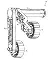
- the belt tensioning device is essential Share with the cylindrical tension pulley 15, which is on the smooth outside of the belt is present, a tension arm 19 and a torsion spring assembly 20 shown.
- the Tensioner pulley 15 is a lightweight plastic part that rests on a journal 21 is rotatably mounted on the tension arm 19.
- the tension arm 19 is a cranked carrier and has weight reducing pockets 22 on one side. The tension arm 19 is held against rotation at the upper end of the torsion spring assembly, the torsion spring assembly 20 is at its lower end with not shown here in detail Middle anchored to the engine block.
- FIG 4 the overall arrangement of Figure 3b is shown larger. It can be seen that the pockets 22 are embossed on one side in the tension arm 19 to reduce weight.
- the bearing pin 21 is shown, on which the tension roller 15 is rotatably mounted by means of a roller bearing 23.
- the bearing inner ring of the bearing is held on the journal 21 by means of a screw 24.
- the tensioning roller 15 encloses the bearing outer ring of the bearing in a form-fitting manner.
- the tensioning roller can thus be rotated about an axis of rotation A 1.
- an eye 25 is formed, into which a bushing 26 is inserted in a rotationally fixed manner, in particular in a press fit.
- One end of a bundle 27 of torsion springs 32 is inserted into the socket 26 and is connected to the socket 26 as a whole in a torsion-proof manner.
- the other end of the bundle 27 of torsion springs 32 is inserted into a bushing 28 which is also connected to this bushing 28 as a whole in a rotationally fixed manner.
- a tube 29 is placed on the sockets 26, 28 and is connected to the socket 28 in a rotationally fixed manner.
- the end of the tube 29 shown above engages over the lower end of the bushing 26, sleeves 30, 31 being inserted between the tube 29 and the bushing 26, which can serve different functions.
- the lower end of the torsion spring assembly 20 is clamped non-rotatably in a holder either directly via the bushing 28 or over the outer circumference of the tube 29.
- the clamping arm 19 is rotatable about the axis A 2 relative to the socket 28.
- the sleeves 30, 31 can serve as bearing sleeves or friction damping sleeves if the upper end of the tube 29 can be rotated relative to the bushing 26 if the dimensions are appropriate.
- the sleeves 30, 31 can also serve as rotary stop sleeves for the upper end of the tube 29 if the tube 29 is to serve as a tubular spring which can be switched sequentially to the torsion spring bundle 27 and which is intended to increase the spring rate from a certain angle of rotation of the torsion spring assembly.
- the sleeves 30, 31 can also serve as clamping sleeves, which produce a rotationally fixed connection between the upper end of the tube 29 and the bushing 26, so that the tube 29 is connected in parallel to the torsion spring assembly 27 and increases the spring rate over the entire torsion angle of the torsion spring assembly. Since a slight shortening of the spring bundle 27 occurs when the spring bundle 27 is twisted, the ends of the spring bundle can be held in at least one of the bushings 26 and 28 or in both torsion-proof but slightly axially displaceable.
- FIG. 5 shows the basic diagram of a belt drive on an internal combustion engine in an axial view of the crankshaft.
- An endless belt 11, in particular a V-ribbed belt or a toothed belt runs over three internal pulleys, namely a pulley 12 mounted on and driven by the crankshaft, which drives the belt drive, a belt-driven pulley 13 for an air conditioning compressor and one of the belt 11 driven pulley 14 for an electric starter generator (starter alternator).
- the toothed belt rotates clockwise.
- the lost drum is located between the pulley 12 and the pulley 14, which is acted upon by a first tensioning roller 15, which can be rotated about an axis of rotation A 1 and is shown in different positions with different belt lengths.
- the first tensioning roller 15 is arranged on a tensioning arm 19 'so as to be pivotable about an axis of rotation A 2 , which at the same time forms the central axis of a torsion spring assembly 20'.
- the tensioning arm 19 ' can be supported on a frame by means of a variable-length link 16, which can comprise damper and / or spring elements.
- a variable-length link 16 which can comprise damper and / or spring elements.
- the second tensioning roller 35 is arranged on a second tensioning arm 39 so as to be pivotable about the axis of rotation A 2 , which has already been mentioned.
- the tensioning arm 39 can be supported by means of a variable-length link 46 relative to the frame, which can include damper and / or spring elements.
- Both tension arms 19, 39 are coupled to one another in a torsionally elastic manner via the torsion spring unit 20 ', which can be freely rotated about the axis of rotation A 2 .
- the torsion spring unit can be installed with a spring preload between the tension arms. In the starter mode, not shown, the tension strand is between the pulley 14 and the pulley 12, while the belt between the pulley 13 and the pulley 14 becomes a lost drum.
- the positions of the tension rollers 15 and 35 are interchanged accordingly when changing to starter operation; the tensioning roller 15 then lies on the tensioned tension strand, while the tensioning roller 35 tensions the lost drum created inwards.
- the tension rollers 15, 35 are in contact with the smooth outside of the belt.
- the middle position PN indicates the nominal position during engine operation, while the neighboring positions PM2 and PE3 represent tolerance ranges and the outer positions PM3 represent the new condition before an initial stretch and the position PE4 represents an end stop beyond the permitted belt stretching and aging.
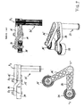
- the belt tensioning device is essential Share with the first tension roller 15, the first tension arm 19 ', the second tension roller 35, the second tension arm 39 and a torsion spring assembly 20 are shown.
- the rollers are lightweight plastic parts, which at the end of their tension arms 19, 39 are rotatably mounted.
- the first clamping arm 19 ' is a straight support, which is at the top End of the torsion spring assembly is held against rotation.
- the second tension arm 39 is a cranked beam that is below the first one on the torsion spring assembly 20 'is held that the tension rollers 15, 35 run in one plane.
- the torsion spring unit 20 ' is preferably freely rotatably mounted in the engine block.
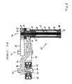
- FIG 8 the overall arrangement of Figure 7b is shown larger.
- the tension arm 19 'with the tension roller 15 is only cut in the area of the torsion spring assembly 20', while the tension arm 39 with the tension roller 35 is shown cut in the middle. It can be seen that pockets 42 are embossed on one side in the tensioning arm 39 to reduce weight.
- a bearing pin 41 is shown, on which the tension roller 35 is rotatably mounted by means of a roller bearing 43.
- the bearing inner ring of the bearing is held on the journal 41 by means of a screw 44.
- the tension roller 35 encloses the bearing outer ring of the bearing in a form-fitting manner.
- the tensioning roller 35 is thus rotatable about an axis of rotation A 2 .
- an eye 25 is formed, in which a bushing 26 is rotatably inserted, in particular in a press fit.
- a bushing 26 is rotatably inserted, in particular in a press fit.
- One end of a bundle 27 of torsion springs 32 is inserted into the socket 26 and is connected to the socket 26 as a whole in a torsion-proof manner.
- the other end of the bundle 27 of torsion springs 32 is inserted into a bushing 28 which is also connected to this bushing 28 as a whole in a rotationally fixed manner.
- a tube 29 is placed on the sockets 26, 28 and is connected to the socket 28 in a rotationally fixed manner. The end of the tube 29 shown above engages over the lower end of the bushing 26, sleeves 30, 31 being inserted between the tube 29 and the bushing 26.
- the sleeves 30, 31 can serve as bearing sleeves or friction damping sleeves with appropriate dimensioning.
- the second clamping arm 39 is non-rotatably placed on the upper end of the tube 29, the second clamping arm 39 is non-rotatably placed.
- the second clamping arm 39 is supported axially downward via a spacer sleeve 40, which is seated on a flange 38.
- Centering sleeves 36, 37 are seated between the tube 29 and the spacer sleeve.
- the second tensioning arm is supported upwards by means of plate springs 33 and friction disks 34 on the first tensioning arm 19 ', which together form a friction damper unit.
- the bundle 27 of torsion springs 32 and the tube 29 form a series connection of springs, which can be installed with appropriate bias against the belt.
- the tensioning arm 19 'with the tensioning roller is supported independently of one another via the bundle 27 and the tensioning arm 39 with the tensioning roller 35 via the tube spring 29 on the bracket from. Since a slight shortening of the spring bundle 27 occurs when the spring bundle 27 is twisted, the ends of the spring bundle can be held non-rotatably in at least one of the bushings 26 and 28 or in both but can be slightly axially displaceable.
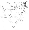
- An endless belt 11, in particular a V-ribbed belt or a toothed belt runs over three inserted pulleys 12, 13, 14, namely a pulley 12 which is mounted on the crankshaft and is driven by it and which drives the belt 11, a pulley 13 driven by the belt 11, e.g. , B. for a compressor of an air conditioning system, and a pulley 14 driven by the belt 11, e.g. B. for an electric starter generator (starter alternator).
- the toothed belt rotates clockwise.
- the lost drum is located between the pulley 12 and the pulley 14 and is acted upon by a first tensioning roller 15, which is shown in different positions with different belt lengths.
- the first tensioning roller 12 is arranged on a tensioning arm 19 so as to be pivotable about an axis of rotation A 2 , which at the same time forms the central axis of a torsion spring assembly 20 1 .
- the second tensioning roller 35 is arranged on a second tensioning arm 39 so as to be pivotable about an axis of rotation A 4 , which at the same time forms the central axis of a second torsion spring assembly 20 2 .
- the axes of rotation A 2 , A 4 are parallel to each other and perpendicular to the plane of the drawing.
- the second tensioning roller 35 rests on the inside of the belt on the tension strand.
- the two torsion spring assemblies 20 1 , 20 2 are coupled such that they can be rotated in opposite directions to one another in the frame.
- the tension strand is located between the pulley 14 and the pulley 12, while the belt between the pulley 13 and the pulley 14 becomes a lost drum.
- the tensioning arm 19 pivots clockwise and the tensioning arm 39 counterclockwise, so that the tensioning roller 35 tensions the slack lost drum to the outside.
- the second tensioning roller 35 lies on the outside of the belt 11.
- Both torsion spring assemblies 20 1 , 20 2 are coupled to one another so that they can be rotated in the frame in the same direction on the tension strand.
- the starter mode (not shown)
- the traction strand is located between the pulley 14 and the pulley 15, while the belt between the pulley 13 and the pulley 14 becomes a lost drum.
- the tensioning roller 15 then lies on the tensioned strand, while the tensioning roller 35 tensions the slack lost strand inwards.
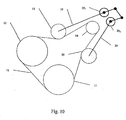
- FIGS. 9 and 10 show in principle the structure and the coupling of the two torsion spring units 20 1 , 20 2 according to FIGS. 9 and 10.
- the torsion spring assemblies each consist of a bundle 27 1 , 27 2 of torsion bars, at the first ends of which tension arms 19, 39 are articulated with tension rollers 15, 35 and at the second ends of crank arms 45 1 , 45 2 , which are connected to one another via a coupling 47 ,
- crank arms 45 1 , 45 2 are arranged parallel to one another in opposite directions (antiparallel) radially on the spring bundles 27, so that the torsion spring units 20 1 , 20 2 are forced to rotate in opposite directions via the coupling 47 1 .
- crank arms 45 1 , 45 2 are arranged in the same direction and in parallel radially on the torsion spring assemblies 20 1 , 20 2 , so that the torsion spring assemblies 20 1 , 20 2 are forced to rotate in the same direction via the coupling 47 2 .
- a relative pretensioning under deformation can occur between the tensioning arms 19, 39 the bundle of torsion springs built up when installing the belt tensioner become.
- the torsion spring assemblies as such are rotatably supported.
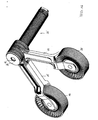
- FIG. 13 shows a further belt tensioning device according to the invention with a cylindrical tension roller 15, a tension arm 19 and a torsion spring assembly 20 shown.
- the tension arm 19 is here composed of two halves, the parting plane approximately in the middle plane of movement of the roller or the tension arm lies and each form a bearing for the tension roller 15. More details can be found in recognize the following figure.
- FIG 14 shows two arm halves 48, 49, the first of which is a socket 50 and the second includes a flat eye 51.
- the halves 48, 49 are joined together connected so that socket 50 and eye 51 together form the eye 25 and can be pushed onto the torsion spring assembly 20.
- At the same time is in each of the halves to recognize a bearing 52, 53 when connected Take up half of the pin for the tension pulley.
- FIG. 15 the construction of the composite clamping arm 19 from the two arm halves 48, 49 can be seen in more detail.
- a journal 21 is inserted into the bearing opening before the halves are assembled.
- the tensioning roller 15 is rotatably mounted in the tensioning arm by means of a roller bearing 23, not shown in detail.
- the tension pulley is rotatable about the axis of rotation A 1 .
- the socket 50 is rotatably connected at the end to a socket 26 which is rotatably inserted into a tube 29 and forms a bearing 54 with it.
- a torsion spring arrangement 32 is inserted into the sleeve 26 in a torsion-proof manner with the upper end.
- the lower end of the torsion spring 32 is inserted non-rotatably in a further socket 28.
- the tube 29 is rotatably and axially connected to the bushing 28.
- a multi-part sleeve 55 is shown, which can form a friction damper between the eye 25 and the upper end of the tube 29.
- the middle plane of movement E of the tensioning roller 15 and the tensioning arm 19, which at the same time forms the parting plane between the halves 48 and 49 lies within the axial region A of the bearing 54.
- the plane E lies approximately in the middle of the axial extent A of the bearing 54.
- Die Bearing 54 between the tension arm 19 and the pipe 29 is thus free of transverse forces or bending moments, so that the function of the bearing is guaranteed to the maximum extent.
- a belt tensioning device is in another Version with a first tensioning roller 15, a first tensioning arm 19 ', a second Tension roller 35, a second tension arm 39 and with a torsion spring assembly 20 'shown.
- the first clamping arm 19 ' which is non-rotatable with a lid-shaped top trained sleeve 26 is connected is fork-like, while the second Clamping arm 39, which is connected to the tube 29 of the torsion spring arrangement 20 ', engages between the two fork parts.
- a torsion spring 32nd engages positively in the sleeve 26.
- Both tension arms 19 'and 39' are made of each put together two halves, as explained in more detail in Figure 14 above.
- FIG. 17 shows the device according to FIG. 16 in a partial section through the central axis A 2 of the torsion spring 32.
- the torsion spring 32 is positively inserted into the sleeve 26 at the top, which is connected in a rotationally fixed manner to the first tensioning arm 19 ′ via its cover-like configuration and is connected in a rotationally fixed manner with its lower end to a sleeve 28.
- the sleeve 28 is in turn connected to the tube 29 in a rotationally fixed manner.
- the second clamping arm 39 which also clearly consists of two halves, is firmly attached.
- sleeves 26 and tube 29 form a bearing 54 with one another.
- the tube 29 is still surrounded by a sleeve 40, with respect to which the tube 29 can be freely rotated.
- the sleeve 40 serves to fix the torsion spring arrangement 20 'in a frame.
- the average plane of movement E of the tensioning rollers, not shown here, and the tensioning arms, which at the same time forms the middle division plane of both tensioning arms 19 'and 39, is also here according to the invention centered on the axial length A of the bearing 54 between the bushing 26 and the tube 29, so that the Bearing arrangement is free of lateral forces or bending moments and also works smoothly with large forces between the clamping arms 19 'and 39.
Landscapes
- Engineering & Computer Science (AREA)
- General Engineering & Computer Science (AREA)
- Life Sciences & Earth Sciences (AREA)
- General Life Sciences & Earth Sciences (AREA)
- Mining & Mineral Resources (AREA)
- Paleontology (AREA)
- Civil Engineering (AREA)
- Structural Engineering (AREA)
- Mechanical Engineering (AREA)
- Environmental & Geological Engineering (AREA)
- Hydrology & Water Resources (AREA)
- Devices For Conveying Motion By Means Of Endless Flexible Members (AREA)
Applications Claiming Priority (4)
| Application Number | Priority Date | Filing Date | Title |
|---|---|---|---|
| DE10300875 | 2003-01-10 | ||
| DE10300875 | 2003-01-10 | ||
| DE10321801.7A DE10321801B4 (de) | 2003-01-10 | 2003-05-14 | Riemenspannvorrichtung |
| DE10321801 | 2003-05-14 |
Publications (3)
| Publication Number | Publication Date |
|---|---|
| EP1437528A2 true EP1437528A2 (fr) | 2004-07-14 |
| EP1437528A3 EP1437528A3 (fr) | 2006-05-10 |
| EP1437528B1 EP1437528B1 (fr) | 2010-03-10 |
Family
ID=32509773
Family Applications (1)
| Application Number | Title | Priority Date | Filing Date |
|---|---|---|---|
| EP04000325A Expired - Lifetime EP1437528B1 (fr) | 2003-01-10 | 2004-01-09 | Tendeur de courroie |
Country Status (4)
| Country | Link |
|---|---|
| US (1) | US7367908B2 (fr) |
| EP (1) | EP1437528B1 (fr) |
| JP (1) | JP4091002B2 (fr) |
| KR (1) | KR100743778B1 (fr) |
Cited By (7)
| Publication number | Priority date | Publication date | Assignee | Title |
|---|---|---|---|---|
| WO2005024271A1 (fr) * | 2003-08-06 | 2005-03-17 | Litens Automotive Gmbh | Dispositif tendeur pour un entrainement rotatif d'un moteur a combustion interne |
| DE10336505B4 (de) * | 2003-08-06 | 2006-12-14 | Litens Automotive Gmbh | Umlauftriebspannvorrichtung für einen Umlauftrieb eines Verbrennungsmotors |
| EP1736688A2 (fr) | 2005-06-24 | 2006-12-27 | Muhr und Bender KG | Tendeur de courroie avec manchon d'amortissement externe |
| DE102007042501A1 (de) | 2007-09-07 | 2009-03-26 | Muhr Und Bender Kg | Riemenspannanordnung |
| FR2959701A1 (fr) * | 2010-05-06 | 2011-11-11 | Peugeot Citroen Automobiles Sa | Motorisation de vehicule comprenant un moteur a combustion interne accouple a un moteur electrique |
| CN109690132A (zh) * | 2016-09-20 | 2019-04-26 | 舍弗勒技术股份两合公司 | 皮带张紧器 |
| US11174921B2 (en) | 2016-09-13 | 2021-11-16 | Litens Automotive Partnership | V tensioner and endless drive arrangement |
Families Citing this family (20)
| Publication number | Priority date | Publication date | Assignee | Title |
|---|---|---|---|---|
| ES2306849T3 (es) * | 2003-04-02 | 2008-11-16 | Dayco Europe S.R.L. | Tensor de correa de dos brazos. |
| ES2322054T3 (es) * | 2004-05-14 | 2009-06-16 | Dayco Europe S.R.L. Con Unico Socio | Tensor de barra de torsion de una transmision por correa de un vehiculo con un dispositivo de amortiguacion mejorado. |
| AT501482B8 (de) * | 2004-05-26 | 2007-02-15 | Gfm Beteiligungs & Man Gmbh | Vorrichtung zum intermittierenden antreiben einer spindel für eine werkstückhalterung, insbesondere einer schmiedemaschine |
| US7913479B2 (en) * | 2007-06-08 | 2011-03-29 | Mtd Products Inc | Two-pulley belt tensioning mechanism |
| US8529387B2 (en) * | 2008-04-30 | 2013-09-10 | Dayco Ip Holdings, Llc | Pulley with asymmetric torque-sensitive clutching |
| US8784244B2 (en) * | 2008-04-30 | 2014-07-22 | Dayco Ip Holdings, Llc | Pulley with asymmetric torque-sensitive clutching |
| DE102008025552B4 (de) | 2008-05-28 | 2020-06-10 | Muhr Und Bender Kg | Riemenspannvorrichtung für Starter-Generator-Anwendung |
| KR101044360B1 (ko) | 2009-12-01 | 2011-06-29 | 대우버스(주) | 버스용 에어컨 컴프레셔 자동 장력조정장치 |
| DE102010019613B4 (de) | 2010-05-06 | 2019-02-21 | Litens Automotive Gmbh | Spanner und Endlostriebanordnung |
| US8888627B2 (en) * | 2010-05-25 | 2014-11-18 | Dayco Ip Holdings, Llc | One-way damped over-arm tensioner |
| US20120152644A1 (en) * | 2010-12-20 | 2012-06-21 | Paul Harriman Kydd | Compliant, balanced belt or chain drive |
| EP2831468B1 (fr) | 2012-03-29 | 2021-12-01 | Litens Automotive Partnership | Tendeur et ensemble d'entraînement sans fin |
| WO2014085917A1 (fr) | 2012-12-07 | 2014-06-12 | Litens Automotive Partnership | Agencement de tendeur et de transmission sans fin |
| DE112014002423B4 (de) * | 2013-05-14 | 2023-01-26 | Litens Automotive Partnership | Spannvorrichtung mit verbesserter Dämpfung |
| JP6355192B2 (ja) * | 2014-05-29 | 2018-07-11 | ダイハツ工業株式会社 | 車両用内燃機関 |
| JP6355193B2 (ja) * | 2014-05-29 | 2018-07-11 | ダイハツ工業株式会社 | 車両用内燃機関 |
| CN111828575A (zh) * | 2019-04-22 | 2020-10-27 | 北京精诚铂阳光电设备有限公司 | 一种传动带张紧轮的支撑件、传动带张紧机构和传输装置 |
| DE102020004335A1 (de) * | 2020-07-20 | 2022-01-20 | Muhr Und Bender Kg | Riemenspannvorrichtung und Riementrieb mit einer solchen Riemenspannvorrichtung |
| FR3125482A1 (fr) | 2021-07-23 | 2023-01-27 | Faurecia Sièges d'Automobile | Glissière pour siège de véhicule, dispositif de glissière, ensemble de siège de véhicule et véhicule automobile |
| DE102022100471B4 (de) | 2022-01-11 | 2025-07-17 | Bayerische Motoren Werke Aktiengesellschaft | Riementrieb zum Antreiben eines Kraftfahrzeugs, insbesondere eines Kraftrads, sowie Kraftfahrzeug, insbesondere Kraftrad |
Citations (1)
| Publication number | Priority date | Publication date | Assignee | Title |
|---|---|---|---|---|
| DE3912944A1 (de) | 1989-03-15 | 1990-09-20 | Muhr & Bender | Riemenspannvorrichtung |
Family Cites Families (19)
| Publication number | Priority date | Publication date | Assignee | Title |
|---|---|---|---|---|
| US660570A (en) * | 1899-11-27 | 1900-10-30 | Acme Harvesting Company | Chain-tightener. |
| US3136170A (en) * | 1962-12-26 | 1964-06-09 | James J Murray | Automatic tensioner |
| US3817113A (en) * | 1971-01-18 | 1974-06-18 | Sulzer Ag | Chain drive with idler wheel tensioning means biased by elongated pads |
| DE3719794A1 (de) * | 1987-06-13 | 1988-12-22 | Skf Gmbh | Schwenklager |
| JPH07109232B2 (ja) * | 1989-10-23 | 1995-11-22 | 三ツ星ベルト株式会社 | オートテンショナー |
| JPH04101848A (ja) | 1990-08-21 | 1992-04-03 | Dainippon Printing Co Ltd | オフセット印刷機のインキ呼出しローラー |
| DE4242293A1 (fr) * | 1991-12-18 | 1993-06-24 | Ntn Toyo Bearing Co Ltd | |
| JPH0672090A (ja) | 1992-08-28 | 1994-03-15 | Ricoh Co Ltd | 動力伝達装置 |
| JP3186871B2 (ja) | 1992-11-18 | 2001-07-11 | 株式会社リコー | 動力伝達装置 |
| JPH0821497A (ja) | 1994-07-07 | 1996-01-23 | Koyo Seiko Co Ltd | オートテンショナ |
| DE4428560A1 (de) * | 1994-08-12 | 1996-02-15 | Schaeffler Waelzlager Kg | Riemenspanneinrichtung mit lamellenförmigen Gleitlagerring |
| JP2951321B1 (ja) * | 1998-06-26 | 1999-09-20 | ユニッタ株式会社 | オートテンショナ |
| JP2002039299A (ja) | 2000-07-26 | 2002-02-06 | Unitta Co Ltd | オートテンショナ |
| MXPA03003936A (es) * | 2000-10-03 | 2003-08-19 | Gates Corp | Tensor de banda para transmision de accesorios y motor/generador. |
| US6575860B2 (en) * | 2001-02-28 | 2003-06-10 | Dayco Products, Llc | Belt tensioner for a power transmission belt system |
| US6960145B2 (en) * | 2002-08-30 | 2005-11-01 | Trw, Inc. | Belt tensioner for electric power steering unit |
| DE10251859A1 (de) * | 2002-11-07 | 2004-05-19 | Ina-Schaeffler Kg | Feder- und Dämpfungsvorrichtung |
| DE10253449A1 (de) * | 2002-11-16 | 2004-05-27 | Bayerische Motoren Werke Ag | Spannvorrichtung für einen Riementrieb von Hilfsaggregaten an einer Brennkraftmaschine |
| DE10253450A1 (de) * | 2002-11-16 | 2004-05-27 | Bayerische Motoren Werke Ag | Spannvorrichtung für einen Hülltrieb eines Aggregates |
-
2004
- 2004-01-09 EP EP04000325A patent/EP1437528B1/fr not_active Expired - Lifetime
- 2004-01-10 KR KR1020040001849A patent/KR100743778B1/ko not_active Expired - Fee Related
- 2004-01-10 US US10/707,769 patent/US7367908B2/en not_active Expired - Lifetime
- 2004-01-13 JP JP2004006083A patent/JP4091002B2/ja not_active Expired - Lifetime
Patent Citations (1)
| Publication number | Priority date | Publication date | Assignee | Title |
|---|---|---|---|---|
| DE3912944A1 (de) | 1989-03-15 | 1990-09-20 | Muhr & Bender | Riemenspannvorrichtung |
Cited By (11)
| Publication number | Priority date | Publication date | Assignee | Title |
|---|---|---|---|---|
| WO2005024271A1 (fr) * | 2003-08-06 | 2005-03-17 | Litens Automotive Gmbh | Dispositif tendeur pour un entrainement rotatif d'un moteur a combustion interne |
| DE10336505B4 (de) * | 2003-08-06 | 2006-12-14 | Litens Automotive Gmbh | Umlauftriebspannvorrichtung für einen Umlauftrieb eines Verbrennungsmotors |
| EP1736688A2 (fr) | 2005-06-24 | 2006-12-27 | Muhr und Bender KG | Tendeur de courroie avec manchon d'amortissement externe |
| DE102005029789A1 (de) * | 2005-06-24 | 2006-12-28 | Muhr Und Bender Kg | Riemenspanner mit außenliegender Dämpfungshülse |
| EP1736688A3 (fr) * | 2005-06-24 | 2007-09-19 | Muhr und Bender KG | Tendeur de courroie avec manchon d'amortissement externe |
| DE102007042501A1 (de) | 2007-09-07 | 2009-03-26 | Muhr Und Bender Kg | Riemenspannanordnung |
| FR2959701A1 (fr) * | 2010-05-06 | 2011-11-11 | Peugeot Citroen Automobiles Sa | Motorisation de vehicule comprenant un moteur a combustion interne accouple a un moteur electrique |
| US11174921B2 (en) | 2016-09-13 | 2021-11-16 | Litens Automotive Partnership | V tensioner and endless drive arrangement |
| CN109690132A (zh) * | 2016-09-20 | 2019-04-26 | 舍弗勒技术股份两合公司 | 皮带张紧器 |
| US11131366B2 (en) | 2016-09-20 | 2021-09-28 | Schaeffler Technologies AG & Co. KG | Belt tensioner |
| CN109690132B (zh) * | 2016-09-20 | 2022-06-17 | 舍弗勒技术股份两合公司 | 皮带张紧器 |
Also Published As
| Publication number | Publication date |
|---|---|
| EP1437528B1 (fr) | 2010-03-10 |
| EP1437528A3 (fr) | 2006-05-10 |
| KR100743778B1 (ko) | 2007-07-30 |
| JP2004218839A (ja) | 2004-08-05 |
| US7367908B2 (en) | 2008-05-06 |
| JP4091002B2 (ja) | 2008-05-28 |
| US20040171448A1 (en) | 2004-09-02 |
| KR20040064646A (ko) | 2004-07-19 |
Similar Documents
| Publication | Publication Date | Title |
|---|---|---|
| EP1437528B1 (fr) | Tendeur de courroie | |
| DE102008025552B4 (de) | Riemenspannvorrichtung für Starter-Generator-Anwendung | |
| EP3613662B1 (fr) | Dérailleur de chaîne pour roue arrière avec agencement de rouleaux de changement de direction de câble excentrique avec rapport de réduction | |
| EP1188003B1 (fr) | Dispositif de tension pour moyens d'entrainement tels que courroies ou chaines | |
| DE3200610A1 (de) | Riemenspannvorrichtung fuer einen von einem motor angetriebenen treibriemen fuer hilfsaggregate von kraftfahrzeugen | |
| DE10321801B4 (de) | Riemenspannvorrichtung | |
| DE102008026064B4 (de) | Riemenspanneranordnung für einen Riementrieb | |
| DE102014008072A1 (de) | Fahrradkettenspanner | |
| DE102018215451A1 (de) | Kraftrad mit einer Spannvorrichtung zum Spannen eines Zugorgans und Spannvorrichtung für ein Kraftrad | |
| DE4408121C2 (de) | Spannvorrichtung zum Aufbringen einer Spannung auf einen bewegten Riemen | |
| DE873951C (de) | Scheibenwischerantrieb | |
| DE2933362C2 (fr) | ||
| DE102004012395B4 (de) | Spanneinheit für einen Aggregatetrieb | |
| DE102010002968A1 (de) | Kraftstoffzufuhrvorrichtung eines V-Motors für ein Kraftrad | |
| EP2123937B1 (fr) | Entraînement de chaîne | |
| DE3546901C2 (de) | Automatische Riemenspannvorrichtung | |
| DE102010002971A1 (de) | Ventilantrieb für Verbrennungsmotoren | |
| EP1420191B1 (fr) | Tendeur pour un courroie de transmission | |
| EP1752321A1 (fr) | Dispositif pour modifier le carrossage | |
| EP1225296B1 (fr) | Dispositif de transfert de couple pour l'entraínement d'une porte, porte et entraínement d'une porte motorisé pourvu d'un tel dispositif | |
| EP1921345B1 (fr) | Dispositif de serrage pour la fixation d' un élément de transmission et usage d'un tel dispositif | |
| DE929228C (de) | Farmschlepper | |
| DE102005035076B4 (de) | Spannsystem | |
| EP2118452B1 (fr) | Système d'entraînement par came | |
| DE102005052453A1 (de) | Spanneinrichtung für ein Zugmittel, insbesondere einen Riemen |
Legal Events
| Date | Code | Title | Description |
|---|---|---|---|
| PUAI | Public reference made under article 153(3) epc to a published international application that has entered the european phase |
Free format text: ORIGINAL CODE: 0009012 |
|
| AK | Designated contracting states |
Kind code of ref document: A2 Designated state(s): AT BE BG CH CY CZ DE DK EE ES FI FR GB GR HU IE IT LI LU MC NL PT RO SE SI SK TR |
|
| AX | Request for extension of the european patent |
Extension state: AL LT LV MK |
|
| PUAL | Search report despatched |
Free format text: ORIGINAL CODE: 0009013 |
|
| AK | Designated contracting states |
Kind code of ref document: A3 Designated state(s): AT BE BG CH CY CZ DE DK EE ES FI FR GB GR HU IE IT LI LU MC NL PT RO SE SI SK TR |
|
| AX | Request for extension of the european patent |
Extension state: AL LT LV MK |
|
| 17P | Request for examination filed |
Effective date: 20060727 |
|
| AKX | Designation fees paid |
Designated state(s): AT BE BG CH CY CZ DE DK EE ES FI FR GB GR HU IE IT LI LU MC NL PT RO SE SI SK TR |
|
| 17Q | First examination report despatched |
Effective date: 20071023 |
|
| GRAP | Despatch of communication of intention to grant a patent |
Free format text: ORIGINAL CODE: EPIDOSNIGR1 |
|
| GRAS | Grant fee paid |
Free format text: ORIGINAL CODE: EPIDOSNIGR3 |
|
| GRAA | (expected) grant |
Free format text: ORIGINAL CODE: 0009210 |
|
| AK | Designated contracting states |
Kind code of ref document: B1 Designated state(s): AT BE BG CH CY CZ DE DK EE ES FI FR GB GR HU IE IT LI LU MC NL PT RO SE SI SK TR |
|
| REG | Reference to a national code |
Ref country code: GB Ref legal event code: FG4D Free format text: NOT ENGLISH |
|
| REG | Reference to a national code |
Ref country code: CH Ref legal event code: EP |
|
| REG | Reference to a national code |
Ref country code: IE Ref legal event code: FG4D |
|
| REF | Corresponds to: |
Ref document number: 502004010867 Country of ref document: DE Date of ref document: 20100422 Kind code of ref document: P |
|
| REG | Reference to a national code |
Ref country code: NL Ref legal event code: VDEP Effective date: 20100310 |
|
| PG25 | Lapsed in a contracting state [announced via postgrant information from national office to epo] |
Ref country code: FI Free format text: LAPSE BECAUSE OF FAILURE TO SUBMIT A TRANSLATION OF THE DESCRIPTION OR TO PAY THE FEE WITHIN THE PRESCRIBED TIME-LIMIT Effective date: 20100310 Ref country code: SI Free format text: LAPSE BECAUSE OF FAILURE TO SUBMIT A TRANSLATION OF THE DESCRIPTION OR TO PAY THE FEE WITHIN THE PRESCRIBED TIME-LIMIT Effective date: 20100310 |
|
| REG | Reference to a national code |
Ref country code: IE Ref legal event code: FD4D |
|
| PG25 | Lapsed in a contracting state [announced via postgrant information from national office to epo] |
Ref country code: CY Free format text: LAPSE BECAUSE OF FAILURE TO SUBMIT A TRANSLATION OF THE DESCRIPTION OR TO PAY THE FEE WITHIN THE PRESCRIBED TIME-LIMIT Effective date: 20100310 Ref country code: EE Free format text: LAPSE BECAUSE OF FAILURE TO SUBMIT A TRANSLATION OF THE DESCRIPTION OR TO PAY THE FEE WITHIN THE PRESCRIBED TIME-LIMIT Effective date: 20100310 Ref country code: ES Free format text: LAPSE BECAUSE OF FAILURE TO SUBMIT A TRANSLATION OF THE DESCRIPTION OR TO PAY THE FEE WITHIN THE PRESCRIBED TIME-LIMIT Effective date: 20100621 Ref country code: NL Free format text: LAPSE BECAUSE OF FAILURE TO SUBMIT A TRANSLATION OF THE DESCRIPTION OR TO PAY THE FEE WITHIN THE PRESCRIBED TIME-LIMIT Effective date: 20100310 Ref country code: RO Free format text: LAPSE BECAUSE OF FAILURE TO SUBMIT A TRANSLATION OF THE DESCRIPTION OR TO PAY THE FEE WITHIN THE PRESCRIBED TIME-LIMIT Effective date: 20100310 Ref country code: SE Free format text: LAPSE BECAUSE OF FAILURE TO SUBMIT A TRANSLATION OF THE DESCRIPTION OR TO PAY THE FEE WITHIN THE PRESCRIBED TIME-LIMIT Effective date: 20100310 Ref country code: GR Free format text: LAPSE BECAUSE OF FAILURE TO SUBMIT A TRANSLATION OF THE DESCRIPTION OR TO PAY THE FEE WITHIN THE PRESCRIBED TIME-LIMIT Effective date: 20100611 |
|
| PG25 | Lapsed in a contracting state [announced via postgrant information from national office to epo] |
Ref country code: SK Free format text: LAPSE BECAUSE OF FAILURE TO SUBMIT A TRANSLATION OF THE DESCRIPTION OR TO PAY THE FEE WITHIN THE PRESCRIBED TIME-LIMIT Effective date: 20100310 Ref country code: BG Free format text: LAPSE BECAUSE OF FAILURE TO SUBMIT A TRANSLATION OF THE DESCRIPTION OR TO PAY THE FEE WITHIN THE PRESCRIBED TIME-LIMIT Effective date: 20100610 Ref country code: CZ Free format text: LAPSE BECAUSE OF FAILURE TO SUBMIT A TRANSLATION OF THE DESCRIPTION OR TO PAY THE FEE WITHIN THE PRESCRIBED TIME-LIMIT Effective date: 20100310 |
|
| PLBE | No opposition filed within time limit |
Free format text: ORIGINAL CODE: 0009261 |
|
| STAA | Information on the status of an ep patent application or granted ep patent |
Free format text: STATUS: NO OPPOSITION FILED WITHIN TIME LIMIT |
|
| PG25 | Lapsed in a contracting state [announced via postgrant information from national office to epo] |
Ref country code: PT Free format text: LAPSE BECAUSE OF FAILURE TO SUBMIT A TRANSLATION OF THE DESCRIPTION OR TO PAY THE FEE WITHIN THE PRESCRIBED TIME-LIMIT Effective date: 20100712 Ref country code: IE Free format text: LAPSE BECAUSE OF FAILURE TO SUBMIT A TRANSLATION OF THE DESCRIPTION OR TO PAY THE FEE WITHIN THE PRESCRIBED TIME-LIMIT Effective date: 20100310 Ref country code: DK Free format text: LAPSE BECAUSE OF FAILURE TO SUBMIT A TRANSLATION OF THE DESCRIPTION OR TO PAY THE FEE WITHIN THE PRESCRIBED TIME-LIMIT Effective date: 20100310 |
|
| 26N | No opposition filed |
Effective date: 20101213 |
|
| PG25 | Lapsed in a contracting state [announced via postgrant information from national office to epo] |
Ref country code: IT Free format text: LAPSE BECAUSE OF FAILURE TO SUBMIT A TRANSLATION OF THE DESCRIPTION OR TO PAY THE FEE WITHIN THE PRESCRIBED TIME-LIMIT Effective date: 20100310 |
|
| BERE | Be: lapsed |
Owner name: BAYERISCHE MOTOREN WERKE A.G. Effective date: 20110131 Owner name: MUHR UND BENDER K.G. Effective date: 20110131 |
|
| PG25 | Lapsed in a contracting state [announced via postgrant information from national office to epo] |
Ref country code: MC Free format text: LAPSE BECAUSE OF NON-PAYMENT OF DUE FEES Effective date: 20110131 |
|
| REG | Reference to a national code |
Ref country code: CH Ref legal event code: PL |
|
| PG25 | Lapsed in a contracting state [announced via postgrant information from national office to epo] |
Ref country code: LI Free format text: LAPSE BECAUSE OF NON-PAYMENT OF DUE FEES Effective date: 20110131 Ref country code: CH Free format text: LAPSE BECAUSE OF NON-PAYMENT OF DUE FEES Effective date: 20110131 |
|
| PG25 | Lapsed in a contracting state [announced via postgrant information from national office to epo] |
Ref country code: BE Free format text: LAPSE BECAUSE OF NON-PAYMENT OF DUE FEES Effective date: 20110131 |
|
| REG | Reference to a national code |
Ref country code: AT Ref legal event code: MM01 Ref document number: 460606 Country of ref document: AT Kind code of ref document: T Effective date: 20110109 |
|
| PG25 | Lapsed in a contracting state [announced via postgrant information from national office to epo] |
Ref country code: AT Free format text: LAPSE BECAUSE OF NON-PAYMENT OF DUE FEES Effective date: 20110109 |
|
| PG25 | Lapsed in a contracting state [announced via postgrant information from national office to epo] |
Ref country code: LU Free format text: LAPSE BECAUSE OF NON-PAYMENT OF DUE FEES Effective date: 20110109 |
|
| PG25 | Lapsed in a contracting state [announced via postgrant information from national office to epo] |
Ref country code: TR Free format text: LAPSE BECAUSE OF FAILURE TO SUBMIT A TRANSLATION OF THE DESCRIPTION OR TO PAY THE FEE WITHIN THE PRESCRIBED TIME-LIMIT Effective date: 20100310 |
|
| PG25 | Lapsed in a contracting state [announced via postgrant information from national office to epo] |
Ref country code: HU Free format text: LAPSE BECAUSE OF FAILURE TO SUBMIT A TRANSLATION OF THE DESCRIPTION OR TO PAY THE FEE WITHIN THE PRESCRIBED TIME-LIMIT Effective date: 20100310 |
|
| REG | Reference to a national code |
Ref country code: FR Ref legal event code: PLFP Year of fee payment: 13 |
|
| REG | Reference to a national code |
Ref country code: FR Ref legal event code: PLFP Year of fee payment: 14 |
|
| REG | Reference to a national code |
Ref country code: FR Ref legal event code: PLFP Year of fee payment: 15 |
|
| PGFP | Annual fee paid to national office [announced via postgrant information from national office to epo] |
Ref country code: FR Payment date: 20230123 Year of fee payment: 20 |
|
| PGFP | Annual fee paid to national office [announced via postgrant information from national office to epo] |
Ref country code: GB Payment date: 20230124 Year of fee payment: 20 Ref country code: DE Payment date: 20230119 Year of fee payment: 20 |
|
| REG | Reference to a national code |
Ref country code: DE Ref legal event code: R071 Ref document number: 502004010867 Country of ref document: DE |
|
| REG | Reference to a national code |
Ref country code: GB Ref legal event code: PE20 Expiry date: 20240108 |
|
| PG25 | Lapsed in a contracting state [announced via postgrant information from national office to epo] |
Ref country code: GB Free format text: LAPSE BECAUSE OF EXPIRATION OF PROTECTION Effective date: 20240108 |