EP1437529A2 - Actionneur linéaire comprenant une vis - Google Patents
Actionneur linéaire comprenant une vis Download PDFInfo
- Publication number
- EP1437529A2 EP1437529A2 EP03017837A EP03017837A EP1437529A2 EP 1437529 A2 EP1437529 A2 EP 1437529A2 EP 03017837 A EP03017837 A EP 03017837A EP 03017837 A EP03017837 A EP 03017837A EP 1437529 A2 EP1437529 A2 EP 1437529A2
- Authority
- EP
- European Patent Office
- Prior art keywords
- worm
- rod
- pin
- previous
- mouthpiece
- Prior art date
- Legal status (The legal status is an assumption and is not a legal conclusion. Google has not performed a legal analysis and makes no representation as to the accuracy of the status listed.)
- Granted
Links
Images

Classifications
-
- F—MECHANICAL ENGINEERING; LIGHTING; HEATING; WEAPONS; BLASTING
- F16—ENGINEERING ELEMENTS AND UNITS; GENERAL MEASURES FOR PRODUCING AND MAINTAINING EFFECTIVE FUNCTIONING OF MACHINES OR INSTALLATIONS; THERMAL INSULATION IN GENERAL
- F16H—GEARING
- F16H25/00—Gearings comprising primarily only cams, cam-followers and screw-and-nut mechanisms
- F16H25/18—Gearings comprising primarily only cams, cam-followers and screw-and-nut mechanisms for conveying or interconverting oscillating or reciprocating motions
- F16H25/20—Screw mechanisms
- F16H25/2025—Screw mechanisms with means to disengage the nut or screw from their counterpart; Means for connecting screw and nut for stopping reciprocating movement
-
- Y—GENERAL TAGGING OF NEW TECHNOLOGICAL DEVELOPMENTS; GENERAL TAGGING OF CROSS-SECTIONAL TECHNOLOGIES SPANNING OVER SEVERAL SECTIONS OF THE IPC; TECHNICAL SUBJECTS COVERED BY FORMER USPC CROSS-REFERENCE ART COLLECTIONS [XRACs] AND DIGESTS
- Y10—TECHNICAL SUBJECTS COVERED BY FORMER USPC
- Y10T—TECHNICAL SUBJECTS COVERED BY FORMER US CLASSIFICATION
- Y10T74/00—Machine element or mechanism
- Y10T74/18—Mechanical movements
- Y10T74/18568—Reciprocating or oscillating to or from alternating rotary
- Y10T74/18576—Reciprocating or oscillating to or from alternating rotary including screw and nut
- Y10T74/18696—Reciprocating or oscillating to or from alternating rotary including screw and nut including means to selectively transmit power [e.g., clutch, etc.]
-
- Y—GENERAL TAGGING OF NEW TECHNOLOGICAL DEVELOPMENTS; GENERAL TAGGING OF CROSS-SECTIONAL TECHNOLOGIES SPANNING OVER SEVERAL SECTIONS OF THE IPC; TECHNICAL SUBJECTS COVERED BY FORMER USPC CROSS-REFERENCE ART COLLECTIONS [XRACs] AND DIGESTS
- Y10—TECHNICAL SUBJECTS COVERED BY FORMER USPC
- Y10T—TECHNICAL SUBJECTS COVERED BY FORMER US CLASSIFICATION
- Y10T74/00—Machine element or mechanism
- Y10T74/19—Gearing
- Y10T74/19642—Directly cooperating gears
- Y10T74/19698—Spiral
- Y10T74/19702—Screw and nut
- Y10T74/19735—Nut disengageable from screw
Definitions
- the present invention refers to a linear motion device associated to a worm.
- the present invention refers to a linear motion device fit to engage with a worm only when the traverse with linear or straight-line motion of mechanical components of machine tools or the like is required.
- Examples of mechanical components wherein the motion device of the present invention can be applied comprise the trolleys with working tools temporarily sliding along guides. This condition can be found, for example, on machines cutting the foil material into films that require a plurality of aligned trolleys bearing blade and/or counter-blade holders.
- trolleys are spaced among them in a proper and variable way in order to obtain, by continuous cutting, some strips of material having different widths.
- Each of said trolleys or supports needs the presence of one nut associated to the lead screw that is rotated by hand or by an engine.
- Object of the present invention is to remedy the above-mentioned drawbacks.
- object of the present invention is the provision of a linear motion device associated to a worm that is easily manufactured and at low costs, it is not bulky and does not need a continuous and difficult maintenance.
- a further object of the present invention is the provision of a device as defined above that temporarily engages with the lead screw and therefore it does not suffer from possible stresses induced by the machine wherein it is applied during the operation.
- a further object of the present invention is the provision of a linear motion device being able to assure a high level of resistance and reliability in time and being also easily manufactured.
- the linear motion device that is associated to a worm and is mainly characterised in that it comprises a box-shaped body which is internally provided with a housing seat and a partial delimitation of said worm and temporary engagement mobile means in at least one of the grooves of the same worm along the part that gets out of said seat.
- the linear motion device of the present invention marked in its whole with 10 in Figure 1, comprises a box-shaped body 12, for example a regular prism body provided with opposite sidewalls 24, 26 and with an upper edge or mouthpiece 20.
- a housing seat of a worm 14 being able to rotate with any suitable means is formed inside said box-shaped body 12.
- Said seat is advantageously obtained in a central position inside the body 12 wherein it is crosswise extended and delimited in its lower part by the internal side of the base of the same body and, sideways, by opposite shoulders 16, 18.
- Said shoulders 16, 18 develop in height for a limited portion while remaining remarkably spaced with their upper end from the edge or mouthpiece 20 of the box-shaped body 12.
- the worm 14 is partially exposed in its part facing said mouthpiece 20 with a sector 22 that preferably corresponds to one fifth of the periphery.
- a sector 22 that preferably corresponds to one fifth of the periphery.
- relevant recesses 28, 30 preferably of regular geometric shape extending in depth for a portion that is lower than the bottom limit of the worm 14 abutted within the base of the same body are obtained.
- Said recesses 28, 30 are fit to house elastic contrast means described here below.
- a covering element or lid 32 that is centrally provided with a projection or turret 34 of any shape and size is fastened to the upper edge or mouthpiece 20.
- the lid 32 is integral to the body 12 with fastening means such as screws 36 or the like.
- the turret 34 of the lid 32 internally defines a housing seat 38 for pressure means that are, for example, constituted by a small pneumatic piston 40 as shown in Figures from 1 to 4.
- the small pneumatic piston 40 is conventionally fed through a fitting 42 and its relevant duct 44 for a working fluid.
- the pressure means is marked , with 46 and it is constituted by a similar small piston that is manually moved for example by a screw 48.
- the pressure means 40 or 46 bears a temporary engagement member with said worm 14 in its lower end facing the body 12 and the worm 14 in order to cause, if necessary, the linear motion of the body 12 in its whole.
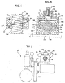
- the body 12 constitutes the traverse vehicle along the worm 14 and a support such as a trolley 50 is connected to it with known means as shown in Figure 7.
- a working tool to cut the materials that is shown and sketched with a dashed line in its whole with 60 or any other means requiring a linear or straight-line motion on a machine tools or equipment is coupled with the trolley 50.
- the member engaging with the worm 14 is advantageously constituted by at least one rod or pin 52 that extends crosswise in the body 12 according to a direction that is parallel to the grooves of the worm 14 marked with 54.
- Said rod 52 is fit into opposite guiding slots 52' obtained on the internal face of the sidewalls 24, 26 of the body 12.
- the crosswise extension of the rod or pin 52 is preferably slightly lower than the whole width of the body 12 and it is higher than the maximum distance existing between the recesses 28, 30.
- the profile of the rod or pin 52 is complementary to the one of said grooves 54 of the worm 14.
- the pressure means 40 or 46 can bear two or more parallel rods or pins 52 fit to match with as many grooves 54 of the worm 14 as described here below.
- contrast elastic means of the rod or pin 52 are constituted by helical springs 56. Said springs 56 keep the rod or pin 52 separated from the grooves of the worm 14, i.e. it is driven upwards towards the lid 32 forming the rebating plane for the same rod.
- the internal surface of the sidewalls 24, 26 of the body 12 defines, together with the mouthpiece of the recesses 28 and 30, a step 58 that is substantially aligned to the grooves 54 of the worm 14 in its part protruding from the shoulders 16, 18.
- Said step 58 can form a stop rebate of the rod or pin 52 of the vertical excursion towards the same worm 14.
- FIGS 1, 2 and 6 schematically show in detail the device 10 of the present invention in a non-operating condition as the rod or pin 52 is moved upwards due to the effect of the elastic means 56 with respect to the grooves 54 of the worm 14.
- FIGs 3 and 4 schematically show the device 10 in operation, its rod or pin 52 is abutted into one of the grooves 54 of the worm 14. This condition occurs after the pneumatic or hand operation of the pressure means 40 or 46 by which said rod or pin 52 lowers towards the body 12 and centrally matches with one of the grooves 54 of the worm 14.
- the clockwise or anti-clockwise rotation of the worm 14, in this case, causes the traverse or linear motion of said body 12 and of all means fastened to it, i.e. of the support or trolley 50 with the relevant tool 60 or of any other kind of tool.
- the linear motion device of the present invention can be easily manufactured and installed at low costs and it does not require a particular maintenance.
- the opportunity of temporarily engaging, if necessary, the device/devices 10 with the worm 14 is particularly advantageous.
Landscapes
- Engineering & Computer Science (AREA)
- General Engineering & Computer Science (AREA)
- Mechanical Engineering (AREA)
- Transmission Devices (AREA)
- Vehicle Body Suspensions (AREA)
- Screw Conveyors (AREA)
- Seats For Vehicles (AREA)
Applications Claiming Priority (2)
| Application Number | Priority Date | Filing Date | Title |
|---|---|---|---|
| ITMI20030038 | 2003-01-13 | ||
| IT000038A ITMI20030038A1 (it) | 2003-01-13 | 2003-01-13 | Dispositivo di movimentazione lineare associato ad una vite senza fine. |
Publications (3)
| Publication Number | Publication Date |
|---|---|
| EP1437529A2 true EP1437529A2 (fr) | 2004-07-14 |
| EP1437529A3 EP1437529A3 (fr) | 2006-11-29 |
| EP1437529B1 EP1437529B1 (fr) | 2009-07-22 |
Family
ID=32500569
Family Applications (1)
| Application Number | Title | Priority Date | Filing Date |
|---|---|---|---|
| EP03017837A Expired - Lifetime EP1437529B1 (fr) | 2003-01-13 | 2003-08-05 | Actionneur linéaire comprenant une vis |
Country Status (7)
| Country | Link |
|---|---|
| US (1) | US7313978B2 (fr) |
| EP (1) | EP1437529B1 (fr) |
| JP (1) | JP3910572B2 (fr) |
| AT (1) | ATE437322T1 (fr) |
| DE (2) | DE03017837T1 (fr) |
| ES (1) | ES2330423T3 (fr) |
| IT (1) | ITMI20030038A1 (fr) |
Cited By (5)
| Publication number | Priority date | Publication date | Assignee | Title |
|---|---|---|---|---|
| DE102007038064A1 (de) | 2007-08-11 | 2009-02-26 | Lsf Maschinen- Und Anlagenbau Gmbh & Co. Kg | Verstelleinrichtung zur Positionierung einer axial geführten Maschineneinheit |
| DE102008059163A1 (de) * | 2008-11-24 | 2010-05-27 | Siemens Aktiengesellschaft | Rüttelfester Verfahrantrieb für ein Schaltgerät sowie Schaltgeräte mit einem derartigen Verfahrantrieb |
| CN101585327B (zh) * | 2008-05-19 | 2012-09-19 | Ims传动装置有限公司 | 用于座椅纵向调整传动机构的丝杆支承装置 |
| WO2019012256A1 (fr) * | 2017-07-14 | 2019-01-17 | Bifold Fluidpower Limited | Actionneur de soupape à sécurité intégrée |
| GB2583530A (en) * | 2019-05-03 | 2020-11-04 | Nemein Ltd | Linear actuator |
Families Citing this family (6)
| Publication number | Priority date | Publication date | Assignee | Title |
|---|---|---|---|---|
| TWI248078B (en) * | 2004-03-03 | 2006-01-21 | Asustek Comp Inc | Automatic oiling device for screw of optical disc player |
| JP4358190B2 (ja) * | 2005-03-16 | 2009-11-04 | 日東電工株式会社 | 粘着剤組成物、粘着シート類および表面保護フィルム |
| FR2998263B1 (fr) * | 2012-11-22 | 2015-07-03 | Messier Bugatti Dowty | Actionneur mecanique avec dispositif d amortissement hydraulique |
| CN109483721A (zh) * | 2018-11-06 | 2019-03-19 | 禹州市华盛钧窑有限公司 | 一种陶瓷加工工作台调节机构 |
| JP2024020727A (ja) * | 2022-08-02 | 2024-02-15 | セイコーエプソン株式会社 | 駆動機構、移動装置、及び、記録装置 |
| US11912324B1 (en) * | 2023-10-19 | 2024-02-27 | Omni Cubed, Inc. | Dolly and cart system with independently slidable jaws |
Family Cites Families (13)
| Publication number | Priority date | Publication date | Assignee | Title |
|---|---|---|---|---|
| US1340468A (en) * | 1917-12-06 | 1920-05-18 | James C H Vaught | Power-drill |
| US1721227A (en) * | 1927-07-18 | 1929-07-16 | Manley Mfg Company | Brake retainer |
| US2141726A (en) * | 1935-05-02 | 1938-12-27 | Bronson Reel Company | Fishing reel |
| US2556572A (en) * | 1944-08-23 | 1951-06-12 | William A Brinkhurst | Screw feed |
| US3546930A (en) * | 1968-11-25 | 1970-12-15 | Clarence A Flarsheim | Rotary to linear motion device with automatic return |
| JPH0510279Y2 (fr) * | 1985-02-28 | 1993-03-12 | ||
| DE3807730A1 (de) * | 1988-03-09 | 1989-09-21 | Will E C H Gmbh & Co | Stelleinrichtung zum veraendern der positionen von gefuehrten einheiten an maschinen |
| US4918783A (en) * | 1989-05-16 | 1990-04-24 | Jack Chu | Adjustable wheel structure |
| GB2247665B (en) * | 1990-09-06 | 1993-09-08 | Carl Morris | Jacking device |
| JPH06201969A (ja) | 1992-12-14 | 1994-07-22 | Asahi Optical Co Ltd | ねじ送り機構の噛み合い角調整装置 |
| FI101416B1 (fi) * | 1994-01-14 | 1998-06-15 | Orion Yhtymae Oy | Siirtolaite lineaarisen siirtoliikkeen toteuttamiseksi |
| JPH07293658A (ja) | 1994-04-27 | 1995-11-07 | Canon Inc | 移動装置 |
| JPH09120649A (ja) | 1995-10-24 | 1997-05-06 | Matsushita Electric Ind Co Ltd | 光ディスク装置 |
-
2003
- 2003-01-13 IT IT000038A patent/ITMI20030038A1/it unknown
- 2003-08-05 ES ES03017837T patent/ES2330423T3/es not_active Expired - Lifetime
- 2003-08-05 EP EP03017837A patent/EP1437529B1/fr not_active Expired - Lifetime
- 2003-08-05 DE DE03017837T patent/DE03017837T1/de active Pending
- 2003-08-05 AT AT03017837T patent/ATE437322T1/de not_active IP Right Cessation
- 2003-08-05 DE DE60328452T patent/DE60328452D1/de not_active Expired - Lifetime
- 2003-08-08 US US10/637,921 patent/US7313978B2/en not_active Expired - Fee Related
- 2003-09-10 JP JP2003318719A patent/JP3910572B2/ja not_active Expired - Fee Related
Cited By (8)
| Publication number | Priority date | Publication date | Assignee | Title |
|---|---|---|---|---|
| DE102007038064A1 (de) | 2007-08-11 | 2009-02-26 | Lsf Maschinen- Und Anlagenbau Gmbh & Co. Kg | Verstelleinrichtung zur Positionierung einer axial geführten Maschineneinheit |
| CN101585327B (zh) * | 2008-05-19 | 2012-09-19 | Ims传动装置有限公司 | 用于座椅纵向调整传动机构的丝杆支承装置 |
| DE102008059163A1 (de) * | 2008-11-24 | 2010-05-27 | Siemens Aktiengesellschaft | Rüttelfester Verfahrantrieb für ein Schaltgerät sowie Schaltgeräte mit einem derartigen Verfahrantrieb |
| CN101741027A (zh) * | 2008-11-24 | 2010-06-16 | 西门子公司 | 开关设备的耐振移动驱动装置和具有该装置的开关设备 |
| DE102008059163B4 (de) * | 2008-11-24 | 2012-09-13 | Siemens Aktiengesellschaft | Rüttelfester Verfahrantrieb für ein Schaltgerät sowie Schaltgeräte mit einem derartigen Verfahrantrieb |
| WO2019012256A1 (fr) * | 2017-07-14 | 2019-01-17 | Bifold Fluidpower Limited | Actionneur de soupape à sécurité intégrée |
| US11156307B2 (en) | 2017-07-14 | 2021-10-26 | Bifold Fluidpower Limited | Failsafe valve actuator |
| GB2583530A (en) * | 2019-05-03 | 2020-11-04 | Nemein Ltd | Linear actuator |
Also Published As
| Publication number | Publication date |
|---|---|
| JP2004218828A (ja) | 2004-08-05 |
| DE03017837T1 (de) | 2007-04-19 |
| ES2330423T3 (es) | 2009-12-10 |
| US20040134296A1 (en) | 2004-07-15 |
| EP1437529A3 (fr) | 2006-11-29 |
| ITMI20030038A1 (it) | 2004-07-14 |
| DE60328452D1 (de) | 2009-09-03 |
| EP1437529B1 (fr) | 2009-07-22 |
| US7313978B2 (en) | 2008-01-01 |
| ATE437322T1 (de) | 2009-08-15 |
| JP3910572B2 (ja) | 2007-04-25 |
Similar Documents
| Publication | Publication Date | Title |
|---|---|---|
| EP1437529A2 (fr) | Actionneur linéaire comprenant une vis | |
| US6079306A (en) | Cutting-off machine for a venetian blind | |
| US3920169A (en) | Driving tool mechanism | |
| US20100126323A1 (en) | Blind cutter | |
| EP3479943B1 (fr) | Machine de découpe de barres de section, fabriquées en particulier en aluminium, alliages légers, pvc ou analogues | |
| US2190213A (en) | Way guard for machine tools | |
| EP3960405B1 (fr) | Scie circulaire à table | |
| DE102007030639A1 (de) | Handwerkzeugmaschine und Führungsschiene dafür | |
| CN112659227B (zh) | 一种密封条切割装置及其环切结构 | |
| CN219293451U (zh) | 一种对刀装置及其机床 | |
| CN116533068A (zh) | 一种磨刀模具 | |
| CN206286647U (zh) | 一种前定位机构切割设备 | |
| CN209223809U (zh) | 一种自动上料的磨床 | |
| CN205766353U (zh) | 一种pu裁断治具 | |
| EP1690622A2 (fr) | Appareil de sciage motorisée | |
| CN105965572A (zh) | 一种pu裁断治具 | |
| US5924351A (en) | Adjustable cut-off head for a wire and strip forming machine | |
| CN209665905U (zh) | 一种圆锯横切机 | |
| SU998004A1 (ru) | Резцова головка дл строгального станка | |
| CN117841299B (zh) | 用于包装行业的包装瓶水口修整装置 | |
| CN110856877A (zh) | 止动机构和切割机 | |
| CN215588893U (zh) | 一种定位装置 | |
| CN109318297B (zh) | 台锯 | |
| CN204735996U (zh) | 直线排列式刀库和机床 | |
| US20060053989A1 (en) | Self-contained cassette material cutter and method of cutting |
Legal Events
| Date | Code | Title | Description |
|---|---|---|---|
| PUAI | Public reference made under article 153(3) epc to a published international application that has entered the european phase |
Free format text: ORIGINAL CODE: 0009012 |
|
| AK | Designated contracting states |
Kind code of ref document: A2 Designated state(s): AT BE BG CH CY CZ DE DK EE ES FI FR GB GR HU IE IT LI LU MC NL PT RO SE SI SK TR |
|
| AX | Request for extension of the european patent |
Extension state: AL LT LV MK |
|
| PUAL | Search report despatched |
Free format text: ORIGINAL CODE: 0009013 |
|
| AK | Designated contracting states |
Kind code of ref document: A3 Designated state(s): AT BE BG CH CY CZ DE DK EE ES FI FR GB GR HU IE IT LI LU MC NL PT RO SE SI SK TR |
|
| AX | Request for extension of the european patent |
Extension state: AL LT LV MK |
|
| 17P | Request for examination filed |
Effective date: 20070206 |
|
| DET | De: translation of patent claims | ||
| AKX | Designation fees paid |
Designated state(s): AT BE BG CH CY CZ DE DK EE ES FI FR GB GR HU IE IT LI LU MC NL PT RO SE SI SK TR |
|
| 17Q | First examination report despatched |
Effective date: 20071105 |
|
| GRAP | Despatch of communication of intention to grant a patent |
Free format text: ORIGINAL CODE: EPIDOSNIGR1 |
|
| GRAS | Grant fee paid |
Free format text: ORIGINAL CODE: EPIDOSNIGR3 |
|
| GRAA | (expected) grant |
Free format text: ORIGINAL CODE: 0009210 |
|
| AK | Designated contracting states |
Kind code of ref document: B1 Designated state(s): AT BE BG CH CY CZ DE DK EE ES FI FR GB GR HU IE IT LI LU MC NL PT RO SE SI SK TR |
|
| REG | Reference to a national code |
Ref country code: GB Ref legal event code: FG4D |
|
| REG | Reference to a national code |
Ref country code: CH Ref legal event code: EP |
|
| REG | Reference to a national code |
Ref country code: IE Ref legal event code: FG4D |
|
| REF | Corresponds to: |
Ref document number: 60328452 Country of ref document: DE Date of ref document: 20090903 Kind code of ref document: P |
|
| REG | Reference to a national code |
Ref country code: ES Ref legal event code: FG2A Ref document number: 2330423 Country of ref document: ES Kind code of ref document: T3 |
|
| NLV1 | Nl: lapsed or annulled due to failure to fulfill the requirements of art. 29p and 29m of the patents act | ||
| PG25 | Lapsed in a contracting state [announced via postgrant information from national office to epo] |
Ref country code: SE Free format text: LAPSE BECAUSE OF FAILURE TO SUBMIT A TRANSLATION OF THE DESCRIPTION OR TO PAY THE FEE WITHIN THE PRESCRIBED TIME-LIMIT Effective date: 20090722 Ref country code: AT Free format text: LAPSE BECAUSE OF FAILURE TO SUBMIT A TRANSLATION OF THE DESCRIPTION OR TO PAY THE FEE WITHIN THE PRESCRIBED TIME-LIMIT Effective date: 20090722 Ref country code: FI Free format text: LAPSE BECAUSE OF FAILURE TO SUBMIT A TRANSLATION OF THE DESCRIPTION OR TO PAY THE FEE WITHIN THE PRESCRIBED TIME-LIMIT Effective date: 20090722 |
|
| PG25 | Lapsed in a contracting state [announced via postgrant information from national office to epo] |
Ref country code: NL Free format text: LAPSE BECAUSE OF FAILURE TO SUBMIT A TRANSLATION OF THE DESCRIPTION OR TO PAY THE FEE WITHIN THE PRESCRIBED TIME-LIMIT Effective date: 20090722 Ref country code: SI Free format text: LAPSE BECAUSE OF FAILURE TO SUBMIT A TRANSLATION OF THE DESCRIPTION OR TO PAY THE FEE WITHIN THE PRESCRIBED TIME-LIMIT Effective date: 20090722 |
|
| PG25 | Lapsed in a contracting state [announced via postgrant information from national office to epo] |
Ref country code: MC Free format text: LAPSE BECAUSE OF NON-PAYMENT OF DUE FEES Effective date: 20090831 Ref country code: BG Free format text: LAPSE BECAUSE OF FAILURE TO SUBMIT A TRANSLATION OF THE DESCRIPTION OR TO PAY THE FEE WITHIN THE PRESCRIBED TIME-LIMIT Effective date: 20091022 Ref country code: PT Free format text: LAPSE BECAUSE OF FAILURE TO SUBMIT A TRANSLATION OF THE DESCRIPTION OR TO PAY THE FEE WITHIN THE PRESCRIBED TIME-LIMIT Effective date: 20091122 |
|
| REG | Reference to a national code |
Ref country code: CH Ref legal event code: PL |
|
| PG25 | Lapsed in a contracting state [announced via postgrant information from national office to epo] |
Ref country code: EE Free format text: LAPSE BECAUSE OF FAILURE TO SUBMIT A TRANSLATION OF THE DESCRIPTION OR TO PAY THE FEE WITHIN THE PRESCRIBED TIME-LIMIT Effective date: 20090722 Ref country code: CH Free format text: LAPSE BECAUSE OF NON-PAYMENT OF DUE FEES Effective date: 20090831 Ref country code: DK Free format text: LAPSE BECAUSE OF FAILURE TO SUBMIT A TRANSLATION OF THE DESCRIPTION OR TO PAY THE FEE WITHIN THE PRESCRIBED TIME-LIMIT Effective date: 20090722 Ref country code: RO Free format text: LAPSE BECAUSE OF FAILURE TO SUBMIT A TRANSLATION OF THE DESCRIPTION OR TO PAY THE FEE WITHIN THE PRESCRIBED TIME-LIMIT Effective date: 20090722 Ref country code: LI Free format text: LAPSE BECAUSE OF NON-PAYMENT OF DUE FEES Effective date: 20090831 Ref country code: CZ Free format text: LAPSE BECAUSE OF FAILURE TO SUBMIT A TRANSLATION OF THE DESCRIPTION OR TO PAY THE FEE WITHIN THE PRESCRIBED TIME-LIMIT Effective date: 20090722 |
|
| PLBE | No opposition filed within time limit |
Free format text: ORIGINAL CODE: 0009261 |
|
| STAA | Information on the status of an ep patent application or granted ep patent |
Free format text: STATUS: NO OPPOSITION FILED WITHIN TIME LIMIT |
|
| PG25 | Lapsed in a contracting state [announced via postgrant information from national office to epo] |
Ref country code: BE Free format text: LAPSE BECAUSE OF FAILURE TO SUBMIT A TRANSLATION OF THE DESCRIPTION OR TO PAY THE FEE WITHIN THE PRESCRIBED TIME-LIMIT Effective date: 20090722 Ref country code: SK Free format text: LAPSE BECAUSE OF FAILURE TO SUBMIT A TRANSLATION OF THE DESCRIPTION OR TO PAY THE FEE WITHIN THE PRESCRIBED TIME-LIMIT Effective date: 20090722 |
|
| 26N | No opposition filed |
Effective date: 20100423 |
|
| PG25 | Lapsed in a contracting state [announced via postgrant information from national office to epo] |
Ref country code: IE Free format text: LAPSE BECAUSE OF NON-PAYMENT OF DUE FEES Effective date: 20090805 |
|
| PG25 | Lapsed in a contracting state [announced via postgrant information from national office to epo] |
Ref country code: GR Free format text: LAPSE BECAUSE OF FAILURE TO SUBMIT A TRANSLATION OF THE DESCRIPTION OR TO PAY THE FEE WITHIN THE PRESCRIBED TIME-LIMIT Effective date: 20091023 |
|
| PG25 | Lapsed in a contracting state [announced via postgrant information from national office to epo] |
Ref country code: LU Free format text: LAPSE BECAUSE OF NON-PAYMENT OF DUE FEES Effective date: 20090805 |
|
| REG | Reference to a national code |
Ref country code: FR Ref legal event code: ST Effective date: 20110502 |
|
| PG25 | Lapsed in a contracting state [announced via postgrant information from national office to epo] |
Ref country code: HU Free format text: LAPSE BECAUSE OF FAILURE TO SUBMIT A TRANSLATION OF THE DESCRIPTION OR TO PAY THE FEE WITHIN THE PRESCRIBED TIME-LIMIT Effective date: 20100123 |
|
| PG25 | Lapsed in a contracting state [announced via postgrant information from national office to epo] |
Ref country code: FR Free format text: LAPSE BECAUSE OF NON-PAYMENT OF DUE FEES Effective date: 20090922 |
|
| PG25 | Lapsed in a contracting state [announced via postgrant information from national office to epo] |
Ref country code: CY Free format text: LAPSE BECAUSE OF FAILURE TO SUBMIT A TRANSLATION OF THE DESCRIPTION OR TO PAY THE FEE WITHIN THE PRESCRIBED TIME-LIMIT Effective date: 20090722 |
|
| PGFP | Annual fee paid to national office [announced via postgrant information from national office to epo] |
Ref country code: TR Payment date: 20200805 Year of fee payment: 18 Ref country code: GB Payment date: 20200810 Year of fee payment: 18 |
|
| PGFP | Annual fee paid to national office [announced via postgrant information from national office to epo] |
Ref country code: IT Payment date: 20200831 Year of fee payment: 18 |
|
| PGFP | Annual fee paid to national office [announced via postgrant information from national office to epo] |
Ref country code: ES Payment date: 20201006 Year of fee payment: 18 Ref country code: DE Payment date: 20201006 Year of fee payment: 18 |
|
| REG | Reference to a national code |
Ref country code: DE Ref legal event code: R119 Ref document number: 60328452 Country of ref document: DE |
|
| GBPC | Gb: european patent ceased through non-payment of renewal fee |
Effective date: 20210805 |
|
| PG25 | Lapsed in a contracting state [announced via postgrant information from national office to epo] |
Ref country code: IT Free format text: LAPSE BECAUSE OF NON-PAYMENT OF DUE FEES Effective date: 20210805 Ref country code: GB Free format text: LAPSE BECAUSE OF NON-PAYMENT OF DUE FEES Effective date: 20210805 Ref country code: DE Free format text: LAPSE BECAUSE OF NON-PAYMENT OF DUE FEES Effective date: 20220301 |
|
| REG | Reference to a national code |
Ref country code: ES Ref legal event code: FD2A Effective date: 20220926 |
|
| PG25 | Lapsed in a contracting state [announced via postgrant information from national office to epo] |
Ref country code: ES Free format text: LAPSE BECAUSE OF NON-PAYMENT OF DUE FEES Effective date: 20210806 |