EP1437544A2 - Indicateur pour véhicules avec de la lumière polarisée - Google Patents
Indicateur pour véhicules avec de la lumière polarisée Download PDFInfo
- Publication number
- EP1437544A2 EP1437544A2 EP04000147A EP04000147A EP1437544A2 EP 1437544 A2 EP1437544 A2 EP 1437544A2 EP 04000147 A EP04000147 A EP 04000147A EP 04000147 A EP04000147 A EP 04000147A EP 1437544 A2 EP1437544 A2 EP 1437544A2
- Authority
- EP
- European Patent Office
- Prior art keywords
- polarized light
- indicator
- vehicle
- light
- splitter
- Prior art date
- Legal status (The legal status is an assumption and is not a legal conclusion. Google has not performed a legal analysis and makes no representation as to the accuracy of the status listed.)
- Granted
Links
Images


Classifications
-
- F—MECHANICAL ENGINEERING; LIGHTING; HEATING; WEAPONS; BLASTING
- F21—LIGHTING
- F21V—FUNCTIONAL FEATURES OR DETAILS OF LIGHTING DEVICES OR SYSTEMS THEREOF; STRUCTURAL COMBINATIONS OF LIGHTING DEVICES WITH OTHER ARTICLES, NOT OTHERWISE PROVIDED FOR
- F21V9/00—Elements for modifying spectral properties, polarisation or intensity of the light emitted, e.g. filters
- F21V9/14—Elements for modifying spectral properties, polarisation or intensity of the light emitted, e.g. filters for producing polarised light
-
- B—PERFORMING OPERATIONS; TRANSPORTING
- B60—VEHICLES IN GENERAL
- B60Q—ARRANGEMENT OF SIGNALLING OR LIGHTING DEVICES, THE MOUNTING OR SUPPORTING THEREOF OR CIRCUITS THEREFOR, FOR VEHICLES IN GENERAL
- B60Q1/00—Arrangement of optical signalling or lighting devices, the mounting or supporting thereof or circuits therefor
- B60Q1/26—Arrangement of optical signalling or lighting devices, the mounting or supporting thereof or circuits therefor the devices being primarily intended to indicate the vehicle, or parts thereof, or to give signals, to other traffic
-
- F—MECHANICAL ENGINEERING; LIGHTING; HEATING; WEAPONS; BLASTING
- F21—LIGHTING
- F21S—NON-PORTABLE LIGHTING DEVICES; SYSTEMS THEREOF; VEHICLE LIGHTING DEVICES SPECIALLY ADAPTED FOR VEHICLE EXTERIORS
- F21S43/00—Signalling devices specially adapted for vehicle exteriors, e.g. brake lamps, direction indicator lights or reversing lights
- F21S43/20—Signalling devices specially adapted for vehicle exteriors, e.g. brake lamps, direction indicator lights or reversing lights characterised by refractors, transparent cover plates, light guides or filters
- F21S43/26—Refractors, transparent cover plates, light guides or filters not provided in groups F21S43/235 - F21S43/255
-
- F—MECHANICAL ENGINEERING; LIGHTING; HEATING; WEAPONS; BLASTING
- F21—LIGHTING
- F21S—NON-PORTABLE LIGHTING DEVICES; SYSTEMS THEREOF; VEHICLE LIGHTING DEVICES SPECIALLY ADAPTED FOR VEHICLE EXTERIORS
- F21S43/00—Signalling devices specially adapted for vehicle exteriors, e.g. brake lamps, direction indicator lights or reversing lights
- F21S43/30—Signalling devices specially adapted for vehicle exteriors, e.g. brake lamps, direction indicator lights or reversing lights characterised by reflectors
- F21S43/31—Optical layout thereof
-
- F—MECHANICAL ENGINEERING; LIGHTING; HEATING; WEAPONS; BLASTING
- F21—LIGHTING
- F21S—NON-PORTABLE LIGHTING DEVICES; SYSTEMS THEREOF; VEHICLE LIGHTING DEVICES SPECIALLY ADAPTED FOR VEHICLE EXTERIORS
- F21S43/00—Signalling devices specially adapted for vehicle exteriors, e.g. brake lamps, direction indicator lights or reversing lights
- F21S43/40—Signalling devices specially adapted for vehicle exteriors, e.g. brake lamps, direction indicator lights or reversing lights characterised by the combination of reflectors and refractors
Definitions
- the present invention relates to an indicator of a vehicle. More specifically, the present invention relates to an indicator that makes a vehicle more visible from a surrounding area even in an adverse condition, such as thick fog or heavy rain.
- an indicator by which a surrounding area (other vehicles, pedestrians etc.) is notified of the existence or information (moving directions etc.) of a vehicle, has been provided on the vehicle.
- a rear fog lamp As examples of the indicator, a rear fog lamp, a width indicator, a number-plate light, a taillight, a parking light, a brake light, a direction indicator, and a hazard indicator can be cited.
- a brake light composed of a plurality of LED lamps and clear beads, which are provided in the bumper made of a clear or diaphanous synthetic resin, is disclosed.
- the visibility of the brake light is improved by scattering the light emitted from respective LED lamps using clear beads.
- un-polarized light is emitted from a light source.
- Un-polarized light tends to be diffused in a horizontal direction and a perpendicular direction with respect to the ground. Since un-polarized light is widely diffused under the adverse condition, such as in a thick fog or a heavy rain, the contour of the vehicle is obscured and thus the visibility of the vehicle from a surrounding area becomes worse. In other words, since the contour of the vehicle becomes unclear when the vehicle is looked from a surrounding area, the presence of the vehicle is not accurately recognized from a surrounding area.
- width indicator As show in FIG. 10A, since un-polarized light emitted from respective width indicators 50A and 50B is diffused in a horizontal direction and a perpendicular direction with respect to a ground, the contour of the vehicle V is obscured when the vehicle V is looked from a surrounding area. Thus, the width of the vehicle V, and the distance from the oncoming vehicle to the vehicle V cannot be recognized by the oncoming vehicle correctly.
- an indicator that can be recognized in an adverse condition, such as thick fog or heavy rain, and that enables the existence of the vehicle adopting the indicator be recognized in a surrounding area.
- the present invention relates to an indicator provided on a vehicle.
- a polarized light splitter which passes and reflects an un-polarized light irradiated from a light source and divides the polarized light into a p-polarized light whose oscillation direction of an electric field is parallel to an incidence plane and an s-polarized light whose oscillation direction of an electric field is perpendicular to the incidence plane.
- At least one of the p-polarized light and s-polarized light is emitted from the polarized light splitter as a horizontal polarized light whose oscillation direction of an electric field is substantially parallel to a ground.
- the oscillation direction of the electric field of at least one of the p-polarized light and the s-polarized light, which are obtained by splitting the incidence light using the polarized light splitter, is substantially parallel with respect to a ground.
- the horizontal polarized light (the light goes in parallel to a ground) is not so diffused under the adverse condition, such as in thick fog or heavy rain, the visibility of the vehicle from a surrounding area can be improved.
- a converter which converts the p-polarized light into the s-polarized light and converts the s-polarized light into the p-polarized light, be provided in the irradiator.
- At least one of the p-polarized light and s-polarized light is emitted from the polarized light splitter as a first horizontal polarized light whose oscillation direction of an electric field is substantially parallel to a ground, and the other of the p-polarized light and s-polarized light is emitted from the polarized light splitter as a second horizontal polarized light whose oscillation direction of an electric field is substantially parallel to a ground after changing the polarization direction by the converter.
- the light (un-polarized light) irradiated from the light source is sufficiently utilized for the irradiation of the light in comparison with the indicator, in which one of the p-polarized light and the s-polarized light obtained by splitting the light in the polarized light splitter is emitted as the horizontal polarized light.
- a polarized beam splitter that efficiently splits the light into the s-polarized light and the p-polarized light may be adoptable as the polarized light splitter.
- a half-wave plate that easily converts the p-polarized light into the s-polarized light and easily converts the s-polarized light into the p-polarized light may be adoptable as the converter.
- the indicator according to the present invention may be adoptable as a rear fog lamp or a width indicator of a vehicle.
- the light emitted from the indicator is not easily diffused in a horizontal direction with respect to a ground in comparison with the conventional indicator emitting the un-polarized light, the presence of the vehicle adopting the present invention's indicator is surely recognized from an oncoming vehicle, a following vehicle, and pedestrian even if the vehicle is traveling in adverse conditions, such as thick fog or heavy rain.
- the present invention's indicator may be used as a rear fog lamp, a width indicator, a number-plate light, a taillight, a parking light, a brake light, a direction indicator, and a hazard indicator.
- FIG.1 is a schematic view used in order to explain a p-polarized light and an s-polarized light.
- FIG.2 is a schematic perspective view used in order to explain the difference among an s-polarized light, a p-polarized light, a horizontal polarized light, and a perpendicular polarized light.
- the p-polarized light is a liner polarized light whose oscillation direction of the electric field (vector of the electric field) is parallel to a plane of incidence.
- the s-polarized light is a liner polarized light whose oscillation direction of the electric field is perpendicular to a plane of incidence.
- the plane of incidence is a plane containing the normal at the point where incidence light strikes a reflection plane, and an optical axis of the incidence light.
- the p-polarized light and s-polarized light are defined with respect to the plane of incidence.
- the perpendicular polarized light and the horizontal polarized light are defined with respect to a ground.
- the polarization whose oscillation direction of the electric field is substantially parallel to a ground is defined as "a horizontal polarized light”.
- the polarization whose oscillation direction of the electric field is substantially perpendicular to a ground is defined as "a perpendicular polarized light”.
- a polarized light splitter is placed so that the plane of incidence (hereinafter defined as "incidence plane") of the polarized light splitter is perpendicular to a ground
- the p-polarized light passed through the polarized light splitter corresponds to the perpendicular polarized light
- the s-polarized light corresponds to the horizontal polarized light.
- a ground corresponds to the reflection plane of FIG.1.
- the p-polarized light and the s-polarized light do not correspond to the perpendicular polarized light and the horizontal polarized light, respectively.
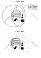
- FIG.3 is a side sectional view that schematically indicates the structure of the indicator 10.
- FIG.4 is a side view that schematically indicates the structure of the polarized beam splitter 13 included in the indicator 10.
- the indicator 10 has a light source 11, a collimator lens 12, a polarized beam splitter 13, a reflecting mirror 14, and a half-wave plate 15.
- Respective components of the indicator 10 are stored in a lamp body 16. An opening provided at opposite side with respect to the light source 11 of the lamp body 16 is covered by a lamp cover 17 made of clear materials, such as glass or acrylic resin.
- a lamp cover 17 made of clear materials, such as glass or acrylic resin.
- a high intensity discharge lamp (HID lamp) is adopted as the light source 11.
- other kinds of light sources such as a halogen lamp and a light-emitting diode (LED) can be adoptable as the light source 11.
- the light (un-polarized light) emitted from the light source 11 strikes on a surface of the collimator lens 12.
- the collimator lens 12 aligns the irradiation angle of the light (un-polarized light) and changes the light (un-polarized light) into parallel beams of light. That is, the collimator lens 12 makes the light (un-polarized light) irradiated from the light source 11 into parallel beams of light by making angles of irradiation in alignment with one another.
- a concave mirror such as a parabolic mirror and the like, may be adoptable instead of the collimator lens 12.
- the parallel beam (un-polarized light) passed through the collimator lens 12 strikes on the polarized beam splitter 13 as an incidence light.
- the polarized beam splitter 13 is one to transmit and reflect the light.
- the incidence light (un-polarized light) passed through the collimator lens 12 is split into a p-polarized light and an s-polarized light by the polarized beam splitter 13.
- the incidence plane of the polarized beam splitter 13 corresponds to the plane of incidence (incidence plane) of FIG. 1, if the reflection plane of FIG. 1 is regarded as a ground.
- the p-polarized light passed through the polarized beam splitter 13 corresponds to the perpendicular polarized light whose oscillation direction of the electric field is substantially vertical to a ground.
- the s-polarized light reflected by the polarized beam splitter 13 corresponds to the horizontal polarized light whose oscillation direction of the electric field is substantially parallel to a ground (see FIG.2A).
- the polarized beam splitter 13 is composed of right-angle prisms 13A and 13B and a multilayer film 13C made of derivatives.
- the multilayer film 13C is provided between opposite surfaces 13c and 13d of right-angle prisms 13A and 13B.
- the right-angle prism 13A is positioned so that the incidence angle of the incidence light, which is supplied through the collimator lens 12 (see FIG.3), becomes perpendicular to the incidence plane 13a.
- the s-polarized light which is obtained by splitting the light (un-polarized light) and which travels in a perpendicular direction with respect to a ground, is emitted from the right-angle prism 13A, when the light (un-polarized light) is entered to the right-angle prism 13A.
- the incidence angle of the incidence light (un-polarized light) with respect to the multilayer film 13C is set at Brewster's angle ⁇ B.
- the angle of the inclination surface 13d of the right-angle prism 13B is the same as that of the inclination surface 13c of the right-angle prism 13A. In other words, the inclination surface 13d is parallel with the inclination surface 13c. Thereby, the p-polarized light whose inclination angle is perpendicular to an emitting plane 13e of the right-angle prism 13B is emitted from the right-angle prism 13B.
- the multilayer film 13C is composed of low refractive index layers 13f and high refractive index layers 13g, which are stacked by turns.
- the high refractive index layer 13g and the low refractive index layer 13f are indicated with exaggeration in size. But, the actual thicknesses of the high refractive index layer 13g and the low refractive index layer 13f are much thinner than illustrated in figure.
- the polarized beam splitter 13 since the p-polarized light is transmitted through the multilayer film 13C and the s-polarized light is reflected by the multilayer film 13C, the p-polarized light and the s-polarized light are separately obtained from the incidence light (un-polarized light).
- the p-polarized light passed through the multilayer film 13C is supplied to the half-wave plate 15 (see FIG.3).
- the s-polarized light reflected by the multilayer film 13C is supplied to the reflecting mirror 14 (see FIG.3).
- nG 2 nH 2 nL 2 / (nL 2 + nH 2 )
- nL is a refractive index of the low refractive index layer 13f
- nH is a refractive index of the high refractive index layer 13g
- nG is a refractive index of the glass.
- the p-polarized light and s-polarized light are obtained from the incidence light (un-polarized light) using the multilayer film 13C.
- the birefringence substances may be adoptable instead of the multilayer film 13C.
- the incidence light is split into the p-polarized light and the s-polarized light, depending on the difference of the spread rate of p-polarized light and the spread rate of s-polarized light.
- a calcite CaCO 3
- the s-polarized light which is reflected by the polarized beam splitter 13 and came from the polarized beam splitter 13, is reflected by the reflecting mirror 14, and the traveling direction of the s-polarized light is changed toward the lamp cover 17.
- the s-polarized light then passes through the lamp cover 17 and is emitted toward the outward as a first horizontal polarized light.
- the half-wave plate 15 displaces the phase of the p-polarized light by half-wavelength and converts it into the s-polarized light.
- the half-wave plate 15 is disposed in an orientation that shifts at 45 degrees with respect to the optical axis of the crystal so that the direction of polarization changes at 90 degrees. Thereby, since the p-polarized light is converted into the s-polarized light by the half-wave plate 15, the s-polarized light goes through the lamp cover 17 and is emitted toward the outward as a second horizontal polarized light.
- the light (un-polarized light) emitted from the light source 11 is adjusted to the light path of respective lights (un-polarized light) parallel with each other, and is entered to the polarized beam splitter 13. Then, the light is split into the p-polarized light and s-polarized light.
- the s-polarized light which is the light whose direction was changed by the multilayer film 13C of the polarized beam splitter 13, is emitted from the polarized beam splitter 13. Then, the s-polarized light reflected by the reflecting mirror 14 goes through the lamp cover 17 and is emitted toward the outward as a first horizontal polarized light.
- the p-polarized light which is the light passed through the multilayer film 13C, is emitted from the polarized beam splitter 13, and is entered to the half-wave plate 15. Then, the p-polarized light is converted into the s-polarized light by the half-wave plate 15 by changing the direction of the polarization (electric field). Then, the light (p-polarized light) passed through the half-wave plate 15 goes through the lamp cover 17 and is emitted outward as the second horizontal polarized light.
- the red colored lamp cover is adopted as the lamp cover 17 (see FIG.3) of rear fog lamps 20A and 20B shown in FIG.5 and FIG. 6.
- rear fog lamps 20A and 20B illuminate at red.
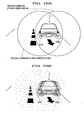
- FIG.5A is an explanatory view showing the region illuminated by the rear fog lamps 20A and 20B, which are provided on the vehicle V.
- FIG.5B is an explanatory view, which looks at the vehicle V traveling in fog from a rear direction.
- the light emitted from the rear fog lamp 20A (20B) is a horizontal polarized light whose oscillation direction of the electric field is substantially parallel to a ground.
- the occurrence of the diffusion of the light can be reduced in comparison with the light emitted from the conventional rear fog lamp 40A (40B) (see FIG.9A).
- the contour in the width directions of the vehicle V traveling in fog can be recognized by the following vehicle.
- the width of the vehicle V and the distance from the following vehicle to the proceeding vehicle V are easily recognized by the following vehicle.
- the visibility of the vehicle looked from the following vehicle has been explained.
- the contour of the vehicle can be recognized by another vehicle and the passenger walking along a road in addition to the following vehicle.
- FIG.6A is an explanatory view showing the region illuminated by the rear fog lamp 20A, which is provided at a center-line side of the vehicle V.
- FIG.6B is an explanatory view, which looks at the vehicle V traveling in fog from a rear direction.
- the rear fog lamp 20A adopts the indicator 10 according to the present invention and the rear fog lamp 40B adopts the conventional indicator
- the horizontal polarized light is only emitted from the rear fog lamp 20A.
- the contour in the center-line side of the vehicle, to which a driver of the following vehicle is paying the attention can be made clear.
- the visibility of the vehicle V from the following vehicle can be improved.
- the indicator 10 of the present invention is provided on the driver's seat side of the vehicle body, the driver on the following vehicle surely recognizes the contour in the driver's seat side of the proceeding vehicle body.
- the white colored lamp cover is adopted as the lamp cover 17 (see FIG.3) of width indicators 30A and 30B shown in FIG.7 and FIG.8.
- the width indicators 30A and 30B illuminate at white.
- FIG.7A is an explanatory view showing the region illuminated by width indicators 30A and 30B, which are provided on the vehicle V.
- FIG.7B is an explanatory view, which looks at the vehicle V traveling in fog from a fore direction.
- the light emitted from width indicators 30A (30B) is a horizontal polarized light whose oscillation direction of the electric field is substantially parallel to a ground (road).
- the occurrence of the diffusion of the light can be reduced as compared to the light emitted from the conventional rear fog lamp 50A (50B) (see FIG.10A).
- the contour in the width directions of the vehicle V traveling in fog can be recognized by the oncoming vehicle.
- the width of the vehicle and the distance from the oncoming vehicle to the vehicle V are easily recognized by the oncoming vehicle.
- the visibility of the vehicle looked from the oncoming vehicle has been explained.
- the contour of the vehicle can be recognized by another vehicle and the passenger walking along a road in addition to the oncoming vehicle.
- FIG.8A is an explanatory view showing the region illuminated by width indicators 30A and 50A.
- FIG.8B is an explanatory view, which looks at the vehicle V traveling in fog from a fore direction.
- the width indicator 30A adopts the indicator 10 according to the present invention and the width indicator 50B adopts the conventional indicator, the horizontal polarized light is only emitted from the width indicator 30A.
- the contour in the center-line side of the vehicle, to which a driver of the following vehicle is paying the attention can be made clear (FIG.8B).
- the visibility of the vehicle V from the oncoming vehicle can be improved.
- the width indicator 10 of the present invention is provided on the driver's seat side of the vehicle body, the driver on the oncoming vehicle surely recognizes the contour in the driver's seat side of the vehicle body.
- p-polarized light and s-polarized light are obtained by splitting the incidence light (un-polarized light) , and the s-polarized light is emitted as the first horizontal polarized light.
- the p-polarized light is emitted as the second horizontal polarized light after converting into the horizontal polarized light by the converter (half wave plate).
- the p-polarized light emitted from the polarized light splitter can be made as the first horizontal polarized light
- the s-polarized light can be made as the second polarized light after converting into the horizontal polarized light by the converter.
- the present invention's indicator can be used as a rear fog lamp, a width indicator, a number-plate light, a taillight, a parking light, a brake light, a direction indicator, and a hazard indicator.
- the oscillation direction of the electric field of at least one of the p-polarized light and the s-polarized light which are obtained by splitting the incidence light using the polarized light splitter (polarized beam splitter 13), is proximately parallel with respect to a ground. Since the horizontal polarized light (the light goes parallel to a ground) is not so diffused under the adverse condition, such as thick fog or heavy rain, the visibility of the vehicle from a surrounding area can be improved.
- one of the p-polarized light and the s-polarized light which are obtained by splitting the incidence light using the polarized light splitter, is emitted as a first horizontal polarized light whose oscillation direction with respect to the electric field is substantially parallel to a ground, and the other of the p-polarized light and the s-polarized light is emitted as a second horizontal polarized light whose oscillation direction with respect to the electric field is substantially parallel to a ground after converting polarization direction (the oscillation direction of the electric field) by the converter.
- both of the p-polarized light and the s-polarized light can be irradiated outward as a horizontal polarized light.
- the light (un-polarized light) irradiated from the light source is sufficiently utilized in comparison with the indicator in which one of the p-polarized light and the s-polarized light that are obtained by splitting the light in the polarized light splitter is emitted as the horizontal polarized light.
- the s-polarized light and the p-polarized light are efficiently obtained by splitting the light.
- the half-wave plate is used as the converter, the conversion from the p-polarized light to the s-polarized light and the conversion from the s-polarized light to the p-polarized light can be achieved easily.
- the indicator according to the present invention is used for the width indicator or the rear fog lamp positioned in the vicinity of the center-line side of the vehicle body, the contour in the center-line side of the vehicle, to which a driver of the following vehicle is paying the attention, can be made clear. Thus, the visibility of the vehicle V from the oncoming vehicle can be further improved.
- An indicator equipped with a polarized light splitter, which passes and reflects an un-polarized light irradiated from a light source and divides the polarized light into a p-polarized light whose oscillation direction of an electric field is parallel to an incidence plane and an s-polarized light whose oscillation direction of an electric field is perpendicular to the incidence plane.
- this indicator at least one of the p-polarized light and s-polarized light is emitted from the polarized light splitter as a horizontal polarized light whose oscillation direction of an electric field is substantially parallel to a ground.
Landscapes
- Engineering & Computer Science (AREA)
- General Engineering & Computer Science (AREA)
- Mechanical Engineering (AREA)
- Physics & Mathematics (AREA)
- Spectroscopy & Molecular Physics (AREA)
- Lighting Device Outwards From Vehicle And Optical Signal (AREA)
- Non-Portable Lighting Devices Or Systems Thereof (AREA)
- Optical Elements Other Than Lenses (AREA)
Applications Claiming Priority (2)
| Application Number | Priority Date | Filing Date | Title |
|---|---|---|---|
| JP2003000908A JP2004214073A (ja) | 2003-01-07 | 2003-01-07 | 告知灯 |
| JP2003000908 | 2003-01-07 |
Publications (3)
| Publication Number | Publication Date |
|---|---|
| EP1437544A2 true EP1437544A2 (fr) | 2004-07-14 |
| EP1437544A3 EP1437544A3 (fr) | 2006-08-02 |
| EP1437544B1 EP1437544B1 (fr) | 2008-02-27 |
Family
ID=32501180
Family Applications (1)
| Application Number | Title | Priority Date | Filing Date |
|---|---|---|---|
| EP04000147A Expired - Lifetime EP1437544B1 (fr) | 2003-01-07 | 2004-01-07 | Indicateur pour véhicules avec de la lumière polarisée |
Country Status (4)
| Country | Link |
|---|---|
| US (1) | US7019631B2 (fr) |
| EP (1) | EP1437544B1 (fr) |
| JP (1) | JP2004214073A (fr) |
| DE (1) | DE602004012001T2 (fr) |
Cited By (1)
| Publication number | Priority date | Publication date | Assignee | Title |
|---|---|---|---|---|
| RU2571035C1 (ru) * | 2014-06-27 | 2015-12-20 | Владимир Иванович Думицкий | Светильник |
Families Citing this family (4)
| Publication number | Priority date | Publication date | Assignee | Title |
|---|---|---|---|---|
| US7688222B2 (en) | 2003-09-18 | 2010-03-30 | Spot Devices, Inc. | Methods, systems and devices related to road mounted indicators for providing visual indications to approaching traffic |
| JP6074790B2 (ja) * | 2012-08-21 | 2017-02-08 | 国立研究開発法人 海上・港湾・航空技術研究所 | 標識灯、標識灯監視装置、及び標識灯監視システム |
| KR101806691B1 (ko) | 2016-04-26 | 2017-12-07 | 현대자동차주식회사 | 헤드램프용 라이트 가이드 장치 |
| KR101981478B1 (ko) * | 2017-03-27 | 2019-05-23 | 현대모비스 주식회사 | 자동차 램프 광학계 |
Family Cites Families (6)
| Publication number | Priority date | Publication date | Assignee | Title |
|---|---|---|---|---|
| GB880374A (en) * | 1956-12-04 | 1961-10-18 | Robert Arthur Smith | Improvements in or relating to devices for producing polarized illumination |
| US3912920A (en) * | 1974-02-06 | 1975-10-14 | Josuke Kubota | Polarized light illumination device |
| JPH05257085A (ja) * | 1992-03-11 | 1993-10-08 | Nikon Corp | 照明光学系 |
| JPH08127297A (ja) | 1994-10-31 | 1996-05-21 | Sekisui Chem Co Ltd | ブレーキランプ付バンパー |
| US5995284A (en) * | 1996-03-29 | 1999-11-30 | 3M Innovative Properties Company | Polarized illumination system for LCD projector |
| JP2003297116A (ja) * | 2002-04-05 | 2003-10-17 | Honda Motor Co Ltd | 投光装置 |
-
2003
- 2003-01-07 JP JP2003000908A patent/JP2004214073A/ja active Pending
- 2003-12-31 US US10/749,254 patent/US7019631B2/en not_active Expired - Fee Related
-
2004
- 2004-01-07 EP EP04000147A patent/EP1437544B1/fr not_active Expired - Lifetime
- 2004-01-07 DE DE602004012001T patent/DE602004012001T2/de not_active Expired - Fee Related
Cited By (1)
| Publication number | Priority date | Publication date | Assignee | Title |
|---|---|---|---|---|
| RU2571035C1 (ru) * | 2014-06-27 | 2015-12-20 | Владимир Иванович Думицкий | Светильник |
Also Published As
| Publication number | Publication date |
|---|---|
| US20040160153A1 (en) | 2004-08-19 |
| US7019631B2 (en) | 2006-03-28 |
| DE602004012001T2 (de) | 2009-02-12 |
| EP1437544A3 (fr) | 2006-08-02 |
| DE602004012001D1 (de) | 2008-04-10 |
| EP1437544B1 (fr) | 2008-02-27 |
| JP2004214073A (ja) | 2004-07-29 |
Similar Documents
| Publication | Publication Date | Title |
|---|---|---|
| JP5257665B2 (ja) | 車両用前照灯ユニット及び車両用前照灯 | |
| US8944649B2 (en) | Vehicle headlight | |
| US7806538B2 (en) | Light source device and vehicle lighting device | |
| EP1351015B1 (fr) | Projecteur de lumière | |
| US7019631B2 (en) | Indicator | |
| KR20220006316A (ko) | 차량용 램프 | |
| KR101822259B1 (ko) | 차량용 조명 장치 | |
| CN114321828B (zh) | 车辆用灯具 | |
| US6084709A (en) | Delineator capable of reflecting oblique incident light beam | |
| KR102565351B1 (ko) | 차량용 램프 장치 | |
| US1954010A (en) | Combined tail-light and reflector signal | |
| KR20180072417A (ko) | 차량용 램프 | |
| US9970616B2 (en) | Lighting apparatus for vehicle | |
| US11946610B2 (en) | Vehicle lamp with rotatable movable unit for road surface pattern emission | |
| US7901119B2 (en) | Vehicle | |
| KR0184801B1 (ko) | 부분반사 코팅층을 가지는 레이져빔 집속렌즈 | |
| KR20170075475A (ko) | 차량용 램프 | |
| KR101181484B1 (ko) | 차량용 램프 | |
| KR20240130296A (ko) | 차량용 램프 | |
| JP2023020646A (ja) | 車両用灯具 | |
| KR20220056471A (ko) | 차량용 램프 | |
| JP2003040031A (ja) | 光学フィルムを用いたハイマウントストップランプ | |
| JPH04334632A (ja) | 補助後退灯 | |
| JPH09226453A (ja) | 車両用表示器 | |
| KR20180070018A (ko) | 차량용 램프 |
Legal Events
| Date | Code | Title | Description |
|---|---|---|---|
| PUAI | Public reference made under article 153(3) epc to a published international application that has entered the european phase |
Free format text: ORIGINAL CODE: 0009012 |
|
| 17P | Request for examination filed |
Effective date: 20040107 |
|
| AK | Designated contracting states |
Kind code of ref document: A2 Designated state(s): AT BE BG CH CY CZ DE DK EE ES FI FR GB GR HU IE IT LI LU MC NL PT RO SE SI SK TR |
|
| AX | Request for extension of the european patent |
Extension state: AL LT LV MK |
|
| PUAL | Search report despatched |
Free format text: ORIGINAL CODE: 0009013 |
|
| AK | Designated contracting states |
Kind code of ref document: A3 Designated state(s): AT BE BG CH CY CZ DE DK EE ES FI FR GB GR HU IE IT LI LU MC NL PT RO SE SI SK TR |
|
| AX | Request for extension of the european patent |
Extension state: AL LT LV MK |
|
| 17Q | First examination report despatched |
Effective date: 20070124 |
|
| AKX | Designation fees paid |
Designated state(s): DE FR GB |
|
| GRAP | Despatch of communication of intention to grant a patent |
Free format text: ORIGINAL CODE: EPIDOSNIGR1 |
|
| GRAS | Grant fee paid |
Free format text: ORIGINAL CODE: EPIDOSNIGR3 |
|
| GRAA | (expected) grant |
Free format text: ORIGINAL CODE: 0009210 |
|
| AK | Designated contracting states |
Kind code of ref document: B1 Designated state(s): DE FR GB |
|
| REG | Reference to a national code |
Ref country code: GB Ref legal event code: FG4D |
|
| REF | Corresponds to: |
Ref document number: 602004012001 Country of ref document: DE Date of ref document: 20080410 Kind code of ref document: P |
|
| ET | Fr: translation filed | ||
| PLBE | No opposition filed within time limit |
Free format text: ORIGINAL CODE: 0009261 |
|
| STAA | Information on the status of an ep patent application or granted ep patent |
Free format text: STATUS: NO OPPOSITION FILED WITHIN TIME LIMIT |
|
| 26N | No opposition filed |
Effective date: 20081128 |
|
| PGFP | Annual fee paid to national office [announced via postgrant information from national office to epo] |
Ref country code: DE Payment date: 20090102 Year of fee payment: 6 |
|
| PGFP | Annual fee paid to national office [announced via postgrant information from national office to epo] |
Ref country code: GB Payment date: 20090107 Year of fee payment: 6 |
|
| PGFP | Annual fee paid to national office [announced via postgrant information from national office to epo] |
Ref country code: FR Payment date: 20090113 Year of fee payment: 6 |
|
| GBPC | Gb: european patent ceased through non-payment of renewal fee |
Effective date: 20100107 |
|
| REG | Reference to a national code |
Ref country code: FR Ref legal event code: ST Effective date: 20100930 |
|
| PG25 | Lapsed in a contracting state [announced via postgrant information from national office to epo] |
Ref country code: FR Free format text: LAPSE BECAUSE OF NON-PAYMENT OF DUE FEES Effective date: 20100201 |
|
| PG25 | Lapsed in a contracting state [announced via postgrant information from national office to epo] |
Ref country code: DE Free format text: LAPSE BECAUSE OF NON-PAYMENT OF DUE FEES Effective date: 20100803 |
|
| PG25 | Lapsed in a contracting state [announced via postgrant information from national office to epo] |
Ref country code: GB Free format text: LAPSE BECAUSE OF NON-PAYMENT OF DUE FEES Effective date: 20100107 |