EP1438507B1 - Pompe a engrenages interieurs - Google Patents
Pompe a engrenages interieurs Download PDFInfo
- Publication number
- EP1438507B1 EP1438507B1 EP02758092A EP02758092A EP1438507B1 EP 1438507 B1 EP1438507 B1 EP 1438507B1 EP 02758092 A EP02758092 A EP 02758092A EP 02758092 A EP02758092 A EP 02758092A EP 1438507 B1 EP1438507 B1 EP 1438507B1
- Authority
- EP
- European Patent Office
- Prior art keywords
- pinion
- gear pump
- internal gear
- compression spring
- toothed ring
- Prior art date
- Legal status (The legal status is an assumption and is not a legal conclusion. Google has not performed a legal analysis and makes no representation as to the accuracy of the status listed.)
- Expired - Lifetime
Links
Images
Classifications
-
- F—MECHANICAL ENGINEERING; LIGHTING; HEATING; WEAPONS; BLASTING
- F04—POSITIVE - DISPLACEMENT MACHINES FOR LIQUIDS; PUMPS FOR LIQUIDS OR ELASTIC FLUIDS
- F04C—ROTARY-PISTON, OR OSCILLATING-PISTON, POSITIVE-DISPLACEMENT MACHINES FOR LIQUIDS; ROTARY-PISTON, OR OSCILLATING-PISTON, POSITIVE-DISPLACEMENT PUMPS
- F04C14/00—Control of, monitoring of, or safety arrangements for, machines, pumps or pumping installations
- F04C14/06—Control of, monitoring of, or safety arrangements for, machines, pumps or pumping installations specially adapted for stopping, starting, idling or no-load operation
-
- F—MECHANICAL ENGINEERING; LIGHTING; HEATING; WEAPONS; BLASTING
- F02—COMBUSTION ENGINES; HOT-GAS OR COMBUSTION-PRODUCT ENGINE PLANTS
- F02M—SUPPLYING COMBUSTION ENGINES IN GENERAL WITH COMBUSTIBLE MIXTURES OR CONSTITUENTS THEREOF
- F02M39/00—Arrangements of fuel-injection apparatus with respect to engines; Pump drives adapted to such arrangements
- F02M39/005—Arrangements of fuel feed-pumps with respect to fuel injection apparatus
-
- F—MECHANICAL ENGINEERING; LIGHTING; HEATING; WEAPONS; BLASTING
- F04—POSITIVE - DISPLACEMENT MACHINES FOR LIQUIDS; PUMPS FOR LIQUIDS OR ELASTIC FLUIDS
- F04C—ROTARY-PISTON, OR OSCILLATING-PISTON, POSITIVE-DISPLACEMENT MACHINES FOR LIQUIDS; ROTARY-PISTON, OR OSCILLATING-PISTON, POSITIVE-DISPLACEMENT PUMPS
- F04C15/00—Component parts, details or accessories of machines, pumps or pumping installations, not provided for in groups F04C2/00 - F04C14/00
- F04C15/0003—Sealing arrangements in rotary-piston machines or pumps
- F04C15/0007—Radial sealings for working fluid
- F04C15/0019—Radial sealing elements specially adapted for intermeshing-engagement type machines or pumps, e.g. gear machines or pumps
-
- F—MECHANICAL ENGINEERING; LIGHTING; HEATING; WEAPONS; BLASTING
- F04—POSITIVE - DISPLACEMENT MACHINES FOR LIQUIDS; PUMPS FOR LIQUIDS OR ELASTIC FLUIDS
- F04C—ROTARY-PISTON, OR OSCILLATING-PISTON, POSITIVE-DISPLACEMENT MACHINES FOR LIQUIDS; ROTARY-PISTON, OR OSCILLATING-PISTON, POSITIVE-DISPLACEMENT PUMPS
- F04C15/00—Component parts, details or accessories of machines, pumps or pumping installations, not provided for in groups F04C2/00 - F04C14/00
- F04C15/0057—Driving elements, brakes, couplings, transmission specially adapted for machines or pumps
- F04C15/0061—Means for transmitting movement from the prime mover to driven parts of the pump, e.g. clutches, couplings, transmissions
- F04C15/0073—Couplings between rotors and input or output shafts acting by interengaging or mating parts, i.e. positive coupling of rotor and shaft
-
- F—MECHANICAL ENGINEERING; LIGHTING; HEATING; WEAPONS; BLASTING
- F04—POSITIVE - DISPLACEMENT MACHINES FOR LIQUIDS; PUMPS FOR LIQUIDS OR ELASTIC FLUIDS
- F04C—ROTARY-PISTON, OR OSCILLATING-PISTON, POSITIVE-DISPLACEMENT MACHINES FOR LIQUIDS; ROTARY-PISTON, OR OSCILLATING-PISTON, POSITIVE-DISPLACEMENT PUMPS
- F04C2/00—Rotary-piston machines or pumps
- F04C2/08—Rotary-piston machines or pumps of intermeshing-engagement type, i.e. with engagement of co-operating members similar to that of toothed gearing
- F04C2/10—Rotary-piston machines or pumps of intermeshing-engagement type, i.e. with engagement of co-operating members similar to that of toothed gearing of internal-axis type with the outer member having more teeth or tooth-equivalents, e.g. rollers, than the inner member
- F04C2/102—Rotary-piston machines or pumps of intermeshing-engagement type, i.e. with engagement of co-operating members similar to that of toothed gearing of internal-axis type with the outer member having more teeth or tooth-equivalents, e.g. rollers, than the inner member the two members rotating simultaneously around their respective axes
Definitions
- the invention relates to an internal gear pump for conveying fuel in an internal combustion engine, with an internally toothed ring gear and an externally toothed pinion, which cooperates with the toothed ring for generating a pumping action.
- Such an internal gear pump is also referred to as a gerotor pump.
- the toothed ring and the pinion represent the pump elements and are also referred to as outer rotor and inner rotor.
- the toothed ring is driven by an electric motor.
- the existing between the teeth of the two pump elements conveying chambers of the internal gear pump are covered in the axial direction by a pressure plate.
- a trained as a compression spring coil spring which is biased against the pressure plate, when starting the internal combustion engine ensures that the axial play is equal to zero.
- Between the electric motor and the toothed ring Oldham clutch is present, which can compensate for axial displacement between the pump and the electric motor.
- an internal gear pump is known, the pinion of which is displaceable in the radial direction.
- the pinion has a bearing stub on the
- the pinion is mounted on two parallel guide surfaces, which allow in conjunction with a correspondingly shaped bearing bore in the pinion and a spring element a radial play compensation of the pinion.
- the object of the invention is to increase the capacity at start speed and the life of the above-described internal gear pump.
- the internal gear pump according to the invention should be inexpensive to produce.
- the pressure in the internal gear pump is equal to zero.
- the pump pressure increases and acts against the spring force.
- the head clearance between the pinion and the pinion increases, which decreases the delivery rate and improves the tribological conditions in the pump by increasing the head clearance.
- the inventive device consists of a transverse bore in the bearing stub and located in the transverse bore second compression spring, wherein the second compression spring is at least indirectly supported against the pinion. Due to the spring force, the pinion is pressed against the toothed ring, as long as the pressure in the interior of the gear pump is small. This is particularly the case when the internal combustion engine and when starting the internal combustion engine of the case, so that automatically results in the desired backlash-free interaction of pinion and ring gear.
- the direction of the transverse bore determines the point at which the tooth tips of the pinion and the toothed ring touch each other. It has proven to be advantageous if the direction of the transverse bore between the suction chamber and the pressure chamber of the pump is located.
- the invention may be provided in a further embodiment, that between the second compression spring and the pinion a pressure piece, in particular a ball is provided so that no sliding friction, but only rolling friction between the second compression spring and pinion occurs.
- the gear pump according to the invention may be provided to make the biasing force of the second compression spring adjustable. This can be achieved, for example, by spacers in the transverse bore or other ball diameters.
- toothed ring is coupled by an Oldham coupling with a clutch disc or a radial elastic coupling with a drive shaft, so that even a slight axial offset of the axis of rotation of the toothed ring and the drive shaft can be compensated and not to undue stress the internal gear pump leads.
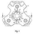
- FIG. 1 shows a high-pressure pump 1 to which an internal gear pump 2 has been attached.
- an externally toothed pinion 3 is rotatably mounted on a bearing stub 5.
- the externally toothed pinion 3 is mounted eccentrically to an internally toothed ring gear 11.
- the toothed ring 11 has two mutually opposite recesses 6 and 7, via which the toothed ring is driven by a drive shaft, not shown in FIG. And a likewise not shown Oldham coupling.
- a tooth tip 13 of the pinion 3 is to be held in contact with a tooth tip 14 of the toothed ring 11 during starting of the internal combustion engine. Once the engine has reached its idle speed, the teeth heads 13 and 14 should lift off each other to reduce their wear.
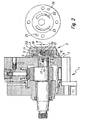
- the internal gear 2 is surrounded by a housing 20 which is fixed to the housing of the high pressure pump 1.
- the bearing stub 5 is part of the housing 20 of the internal gear pump 2. From the high pressure pump 1 protrudes a shaft end 21 to about a flange 7 of the high-pressure pump 1. At the flange 7, the internal gear 2 is flanged to the high-pressure pump 1.
- a recess 8 is formed at the shaft end 21, a recess 8 is formed.
- the recess 8 has two mutually parallel side walls, which are not visible in Figure 2. These parallel side walls extend in the position of the shaft end 21 shown in Figure 2 perpendicular to the plane of the drawing.
- a clutch disc 9 In the recess 8 protrudes a clutch disc 9 with a two edge 10.
- the parallel side walls of the recess 9 and the two edges 10 of the clutch disc 9 allow the transmission of the required to drive the internal gear 2 torque from the shaft end 21 on the clutch disc.
- the recesses 6 have, as shown in Fig. 1, two mutually parallel side walls 15, in the radial Direction. In Fig. 2, the side walls 15 are parallel to the plane of the drawing.
- the recess 8, clutch disc 9 with the two edge 10 and the lugs 12 and the recesses 6 form a so-called Oldham coupling, which is also referred to as a cross-plate clutch. It serves to transmit the rotational movement of the drive shaft end 21 to the toothed ring 11 of the internal gear pump 2 even when the axis offset. In this case, the funnelusionnkupplung allows that an axial offset between the drive shaft end 21 and the axis of rotation of the toothed ring 11 can be compensated.
- a first compression spring 16 is provided, which is supported at one end against the shaft end 21 and the other end against the two edge 10.
- the clutch disc 9 is pressed against the toothed ring 11, so that the internal gear pump 2 has at least at a standstill no axial play to the outside.
- An axial clearance of, for example, 0.005 mm between pinion 3 and clutch disc 9 should be present at the start of the pump.
- the bearing stub 5 In the bearing stub 5 is a transverse bore 17 which receives a second compression spring 18 and a ball 19, is present.
- the second compression spring 18 presses the pinion 3 against the toothed ring 11 so that no play between the tooth head 13 of the pinion 3 and the tooth head of the toothed ring 11 is present at a standstill of the internal gear pump 2.
- an inlet channel 22 and a delivery channel 23 can be seen in the pump housing, via which the fuel is sucked in by the high-pressure pump (not shown), not shown.
- the fuel (not shown) flows via an inlet bore 24 to the inlet channel 22 and flows out of the conveyor channel 23 into a delivery bore 25.
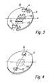
- a first embodiment of a clutch disc 9 according to the invention is shown in perspective.
- the clutch disc 9 is made in this embodiment of a piece of sheet metal.
- the lugs 12 have been formed by Nachobenbiegen of two cut sheet metal strip of the clutch disc 9.
- the two-edge 10 which is shown only by dashed lines, has been formed in this embodiment by two folded down metal strips of the clutch disc 9.
- recess 6 of the toothed ring 11 and the not shown recess 8 in the shaft end 21 allows the clutch disc 9, as indicated by the arrows in Fig. 3, compensating movements in the X and Y directions.
- an axial offset between the axis of rotation of the shaft end 21 and the toothed ring 11 can be compensated.
- a second embodiment of a clutch disc 9 according to the invention is shown in perspective.
- the clutch disc 9 is, for example, manufactured by sintering or die casting.
- the lugs 12 and the two edge 10 are sintered in this embodiment of the actual clutch plate 9, or cast.
Landscapes
- Engineering & Computer Science (AREA)
- Mechanical Engineering (AREA)
- General Engineering & Computer Science (AREA)
- Chemical & Material Sciences (AREA)
- Combustion & Propulsion (AREA)
- Details And Applications Of Rotary Liquid Pumps (AREA)
- Rotary Pumps (AREA)
Claims (7)
- Pompe à engrenages intérieurs pour transporter du carburant dans un moteur à combustion interne, comprenant une couronne dentée à denture intérieure (11) et un pignon à engrenages extérieurs (3) qui coopère avec la couronne dentée (11) pour générer un effet de pompage, le pignon (3) étant logé de façon excentrée par rapport à la couronne dentée (11) sur un bout de palier (5),
caractérisée en ce que
le pignon (3) est logé de façon mobile radialement sur le bout de palier (5) et un alésage transversal (17) est prévu dans le bout de palier (5), un deuxième ressort de pression (18) est situé dans l'alésage transversal (17), et le deuxième ressort de pression (18) s'appuie au moins indirectement contre le pignon (3) pour équilibrer le jeu radial entre le pignon (3) et la couronne dentée (11) en particulier au démarrage du moteur à combustion interne. - Pompe à engrenages intérieurs selon la revendication 1,
caractérisée en ce qu'
une pièce de pression, en particulier une bille (19), est prévue entre le deuxième ressort de pression (18) et le pignon (3). - Pompe à engrenages intérieurs selon la revendication 1 ou 2,
caractérisée en ce que
la force de précontrainte du deuxième ressort de pression (18) est réglable. - Pompe à engrenages intérieurs selon l'une quelconque des revendications précédentes,
caractérisée en ce que
le pignon (3) est couplé par un accouplement Oldham (8, 9, 10, 12, 6, 11) à un disque d'embrayage (22) ou un couplage radialement élastique est couplé à un arbre d'entraînement (21). - Pompe à engrenages intérieurs selon la revendication 4,
caractérisée en ce que
le disque d'embrayage (22) est pressé par un premier ressort de pression (16) sur la couronne dentée (11). - Pompe à engrenages intérieurs selon la revendication 5,
caractérisée en ce que
le premier ressort de pression (16) est disposé dans l'extrémité d'arbre (21). - Pompe à engrenages intérieurs selon la revendication 5 ou 6,
caractérisée en ce que
la force de précontrainte du premier ressort de pression (16) est réglable.
Applications Claiming Priority (3)
| Application Number | Priority Date | Filing Date | Title |
|---|---|---|---|
| DE10150653 | 2001-10-13 | ||
| DE10150653A DE10150653A1 (de) | 2001-10-13 | 2001-10-13 | Innenzahnradpumpe |
| PCT/DE2002/002577 WO2003036091A1 (fr) | 2001-10-13 | 2002-07-13 | Pompe a engrenages interieurs |
Publications (2)
| Publication Number | Publication Date |
|---|---|
| EP1438507A1 EP1438507A1 (fr) | 2004-07-21 |
| EP1438507B1 true EP1438507B1 (fr) | 2007-04-11 |
Family
ID=7702441
Family Applications (1)
| Application Number | Title | Priority Date | Filing Date |
|---|---|---|---|
| EP02758092A Expired - Lifetime EP1438507B1 (fr) | 2001-10-13 | 2002-07-13 | Pompe a engrenages interieurs |
Country Status (7)
| Country | Link |
|---|---|
| US (1) | US7052257B2 (fr) |
| EP (1) | EP1438507B1 (fr) |
| JP (1) | JP4188836B2 (fr) |
| CN (1) | CN1284931C (fr) |
| AT (1) | ATE359444T1 (fr) |
| DE (2) | DE10150653A1 (fr) |
| WO (1) | WO2003036091A1 (fr) |
Cited By (2)
| Publication number | Priority date | Publication date | Assignee | Title |
|---|---|---|---|---|
| CN102257275A (zh) * | 2008-12-16 | 2011-11-23 | 罗伯特·博世有限公司 | 内齿轮泵 |
| DE102021201302A1 (de) | 2021-02-11 | 2022-08-11 | Magna powertrain gmbh & co kg | Gerotorpumpe |
Families Citing this family (12)
| Publication number | Priority date | Publication date | Assignee | Title |
|---|---|---|---|---|
| DE10337847A1 (de) * | 2003-08-18 | 2005-03-17 | Robert Bosch Gmbh | Pumpenanordnung mit einer Hochdruckpumpe und einer dieser vorgeschalteten Niederdruckpumpe für eine Kraftstoffeinspritzeinrichtung einer Brennkraftmaschine |
| BRPI0414231B1 (pt) * | 2003-09-11 | 2013-03-19 | mÁquina de Êmbolo rotativo. | |
| JP2007505249A (ja) * | 2003-09-11 | 2007-03-08 | コア・ポンプス・プルス・コンプレッサーズ・アクチエンゲゼルシャフト | 回転ピストン機械 |
| DE102006037177A1 (de) * | 2006-08-09 | 2008-02-14 | Robert Bosch Gmbh | Innenzahnradpumpe |
| US7669577B2 (en) * | 2008-02-07 | 2010-03-02 | Kohler Co. | Gerotor and method of assembling the same |
| US20100322806A1 (en) * | 2009-06-18 | 2010-12-23 | Aregger Markus | Arrangement including a gear pump |
| DE102010000850A1 (de) * | 2010-01-13 | 2011-07-14 | Robert Bosch GmbH, 70469 | Kupplung, insbesondere zum Koppeln einer Hochdruckpumpe mit einer Zahnradpumpe |
| DE102012218397A1 (de) | 2012-10-10 | 2014-04-10 | Robert Bosch Gmbh | Hydrostatische Maschine |
| DE102013210036A1 (de) * | 2013-05-29 | 2014-12-04 | Robert Bosch Gmbh | Hochdruckpumpe für ein Kraftstoffeinspritzsystem |
| KR20150071188A (ko) * | 2013-12-18 | 2015-06-26 | 현대자동차주식회사 | 펌프 구조 |
| GB2559148B (en) * | 2017-01-26 | 2019-06-05 | Delphi Tech Ip Ltd | Driveshaft with transfer pump adapter |
| US12140141B1 (en) * | 2024-04-30 | 2024-11-12 | Hangzhou Quadrant Technology Co., Ltd. | Electric oil pump including pump housing and eccentric assembly non-concentrically arranged with pump housing |
Family Cites Families (14)
| Publication number | Priority date | Publication date | Assignee | Title |
|---|---|---|---|---|
| US1497050A (en) * | 1923-10-25 | 1924-06-10 | Hill Compressor & Pump Company | Rotary pump |
| DE590394C (de) | 1931-01-30 | 1933-12-30 | Const Mecaniques L Aster Atel | Pumpe mit zylindrischem Gehaeuse |
| CH262067A (fr) | 1946-02-02 | 1949-06-15 | Quaglia Senta Ulrico | Pompe rotative sans soupapes. |
| US3536426A (en) | 1968-04-03 | 1970-10-27 | Novelty Tool Co Inc | Gear pump having eccentrically arranged internal and external gears |
| US4156585A (en) | 1977-10-03 | 1979-05-29 | Borg-Warner Corporation | Gerotor device with porting through eccentric drive |
| DE2814659C2 (de) | 1978-04-05 | 1984-02-02 | Danfoss A/S, 6430 Nordborg | Zahnradpumpe |
| DE2829417C3 (de) * | 1978-07-05 | 1984-07-12 | Mannesmann Rexroth GmbH, 8770 Lohr | Arbeitsmittelsteuerung für eine parallel- und innenachsige Rotationskolbenmaschine |
| DE8226081U1 (de) * | 1982-09-16 | 1984-02-23 | Arthur Pfeiffer Vakuumtechnik Wetzlar Gmbh, 6334 Asslar | Kupplungsanordnung fuer zweistufige drehschieberpumpen |
| JPS6248977A (ja) | 1985-08-27 | 1987-03-03 | Honda Motor Co Ltd | 内燃機関用流体ポンプ |
| DE3827573A1 (de) * | 1988-08-13 | 1990-02-15 | Bosch Gmbh Robert | Vorrichtung zum foerdern von kraftstoff aus einem vorratstank zur brennkraftmaschine, insbesondere eines kraftfahrzeuges |
| US5145348A (en) * | 1991-05-15 | 1992-09-08 | Eaton Corporation | Gerotor pump having an improved drive mechanism |
| JPH06249155A (ja) * | 1993-02-23 | 1994-09-06 | Toyoda Mach Works Ltd | 歯車ポンプ |
| DE19651683A1 (de) * | 1996-12-12 | 1998-06-18 | Otto Eckerle | Füllstücklose Innenzahnradpumpe |
| DE10035900A1 (de) * | 2000-07-21 | 2002-01-31 | Bosch Gmbh Robert | Innenzahnradpumpe |
-
2001
- 2001-10-13 DE DE10150653A patent/DE10150653A1/de not_active Ceased
-
2002
- 2002-07-13 DE DE50209940T patent/DE50209940D1/de not_active Expired - Lifetime
- 2002-07-13 WO PCT/DE2002/002577 patent/WO2003036091A1/fr not_active Ceased
- 2002-07-13 CN CNB028020375A patent/CN1284931C/zh not_active Expired - Fee Related
- 2002-07-13 US US10/450,462 patent/US7052257B2/en not_active Expired - Fee Related
- 2002-07-13 AT AT02758092T patent/ATE359444T1/de not_active IP Right Cessation
- 2002-07-13 EP EP02758092A patent/EP1438507B1/fr not_active Expired - Lifetime
- 2002-07-13 JP JP2003538572A patent/JP4188836B2/ja not_active Expired - Lifetime
Cited By (3)
| Publication number | Priority date | Publication date | Assignee | Title |
|---|---|---|---|---|
| CN102257275A (zh) * | 2008-12-16 | 2011-11-23 | 罗伯特·博世有限公司 | 内齿轮泵 |
| CN102257275B (zh) * | 2008-12-16 | 2016-05-04 | 罗伯特·博世有限公司 | 内齿轮泵以及内燃机和用于内燃机的燃料喷射系统 |
| DE102021201302A1 (de) | 2021-02-11 | 2022-08-11 | Magna powertrain gmbh & co kg | Gerotorpumpe |
Also Published As
| Publication number | Publication date |
|---|---|
| DE10150653A1 (de) | 2003-04-30 |
| JP2005506490A (ja) | 2005-03-03 |
| US20040219038A1 (en) | 2004-11-04 |
| WO2003036091A1 (fr) | 2003-05-01 |
| CN1284931C (zh) | 2006-11-15 |
| ATE359444T1 (de) | 2007-05-15 |
| EP1438507A1 (fr) | 2004-07-21 |
| DE50209940D1 (de) | 2007-05-24 |
| JP4188836B2 (ja) | 2008-12-03 |
| US7052257B2 (en) | 2006-05-30 |
| CN1463330A (zh) | 2003-12-24 |
Similar Documents
| Publication | Publication Date | Title |
|---|---|---|
| EP1438507B1 (fr) | Pompe a engrenages interieurs | |
| EP2079923B1 (fr) | Pompe à piston, notamment pompe de carburant haute pression, avec poussoir à galet | |
| EP1305523B1 (fr) | Pompe a engrenages interieurs | |
| DE102004038681A1 (de) | Elektromotorischer Nockenwellenversteller | |
| EP3421802B1 (fr) | Pompe à gaz avec limiteur de pression pour la réduction du couple de démarrage | |
| EP1927754A1 (fr) | Pompe à engrenages intérieurs | |
| EP0666422B1 (fr) | Paliers et système d'entraînement pour les rotors d'un compresseur à vis | |
| DE102015119263A1 (de) | Pumpe-Motor-Einheit | |
| EP3077135A1 (fr) | Machine-outil pouvant être entraînée en oscillation | |
| DE1403909A1 (de) | Zahnradpumpe | |
| EP4314560B1 (fr) | Machine fluidique à engrenages intérieurs et procédé de fabrication d'une machine fluidique à engrenages intérieurs | |
| EP1209359A2 (fr) | Pompe à engrenages | |
| EP2419635B1 (fr) | Pompe à piston avec entraînement par came, en particulier pompe à carburant | |
| EP1311762B1 (fr) | Pompe a engrenages a denture interieure | |
| EP3249156B1 (fr) | Machine, en particulier pompe de pression d'huile | |
| EP1658438B1 (fr) | Pompe a liquides | |
| DE3624382A1 (de) | Exzentrische sperrschieberpumpe, insbesondere zur foerderung von schmierstoffen fuer antriebe | |
| EP2379891A2 (fr) | Pompe à engrenage intérieur | |
| DE19827924B4 (de) | Hydraulikpumpe | |
| DE10226492B4 (de) | Axialkolbenmaschine mit verstellbarem Kolbenhub | |
| EP0315878A2 (fr) | Pompe à engrènement interne | |
| DE102009013986A1 (de) | Verstellbare Rotorpumpe | |
| DE202009003981U1 (de) | Antrieb für eine Vakuumpumpe | |
| DE2541028A1 (de) | Zahnradpumpe | |
| EP2872778B1 (fr) | Pompe à haute pression |
Legal Events
| Date | Code | Title | Description |
|---|---|---|---|
| PUAI | Public reference made under article 153(3) epc to a published international application that has entered the european phase |
Free format text: ORIGINAL CODE: 0009012 |
|
| 17P | Request for examination filed |
Effective date: 20040513 |
|
| AK | Designated contracting states |
Kind code of ref document: A1 Designated state(s): AT BE BG CH CY CZ DE DK EE ES FI FR GB GR IE IT LI LU MC NL PT SE SK TR |
|
| GRAP | Despatch of communication of intention to grant a patent |
Free format text: ORIGINAL CODE: EPIDOSNIGR1 |
|
| GRAS | Grant fee paid |
Free format text: ORIGINAL CODE: EPIDOSNIGR3 |
|
| GRAA | (expected) grant |
Free format text: ORIGINAL CODE: 0009210 |
|
| AK | Designated contracting states |
Kind code of ref document: B1 Designated state(s): AT BE BG CH CY CZ DE DK EE ES FI FR GB GR IE IT LI LU MC NL PT SE SK TR |
|
| PG25 | Lapsed in a contracting state [announced via postgrant information from national office to epo] |
Ref country code: FI Free format text: LAPSE BECAUSE OF FAILURE TO SUBMIT A TRANSLATION OF THE DESCRIPTION OR TO PAY THE FEE WITHIN THE PRESCRIBED TIME-LIMIT Effective date: 20070411 |
|
| REG | Reference to a national code |
Ref country code: GB Ref legal event code: FG4D Free format text: NOT ENGLISH |
|
| REG | Reference to a national code |
Ref country code: CH Ref legal event code: EP |
|
| REG | Reference to a national code |
Ref country code: IE Ref legal event code: FG4D Free format text: LANGUAGE OF EP DOCUMENT: GERMAN |
|
| REF | Corresponds to: |
Ref document number: 50209940 Country of ref document: DE Date of ref document: 20070524 Kind code of ref document: P |
|
| PG25 | Lapsed in a contracting state [announced via postgrant information from national office to epo] |
Ref country code: SE Free format text: LAPSE BECAUSE OF FAILURE TO SUBMIT A TRANSLATION OF THE DESCRIPTION OR TO PAY THE FEE WITHIN THE PRESCRIBED TIME-LIMIT Effective date: 20070711 |
|
| PG25 | Lapsed in a contracting state [announced via postgrant information from national office to epo] |
Ref country code: ES Free format text: LAPSE BECAUSE OF FAILURE TO SUBMIT A TRANSLATION OF THE DESCRIPTION OR TO PAY THE FEE WITHIN THE PRESCRIBED TIME-LIMIT Effective date: 20070722 |
|
| PG25 | Lapsed in a contracting state [announced via postgrant information from national office to epo] |
Ref country code: PT Free format text: LAPSE BECAUSE OF FAILURE TO SUBMIT A TRANSLATION OF THE DESCRIPTION OR TO PAY THE FEE WITHIN THE PRESCRIBED TIME-LIMIT Effective date: 20070911 |
|
| NLV1 | Nl: lapsed or annulled due to failure to fulfill the requirements of art. 29p and 29m of the patents act | ||
| GBV | Gb: ep patent (uk) treated as always having been void in accordance with gb section 77(7)/1977 [no translation filed] |
Effective date: 20070411 |
|
| REG | Reference to a national code |
Ref country code: IE Ref legal event code: FD4D |
|
| EN | Fr: translation not filed | ||
| BERE | Be: lapsed |
Owner name: ROBERT BOSCH G.M.B.H. Effective date: 20070731 |
|
| PG25 | Lapsed in a contracting state [announced via postgrant information from national office to epo] |
Ref country code: CZ Free format text: LAPSE BECAUSE OF FAILURE TO SUBMIT A TRANSLATION OF THE DESCRIPTION OR TO PAY THE FEE WITHIN THE PRESCRIBED TIME-LIMIT Effective date: 20070411 Ref country code: BG Free format text: LAPSE BECAUSE OF FAILURE TO SUBMIT A TRANSLATION OF THE DESCRIPTION OR TO PAY THE FEE WITHIN THE PRESCRIBED TIME-LIMIT Effective date: 20070711 Ref country code: DK Free format text: LAPSE BECAUSE OF FAILURE TO SUBMIT A TRANSLATION OF THE DESCRIPTION OR TO PAY THE FEE WITHIN THE PRESCRIBED TIME-LIMIT Effective date: 20070411 Ref country code: IE Free format text: LAPSE BECAUSE OF FAILURE TO SUBMIT A TRANSLATION OF THE DESCRIPTION OR TO PAY THE FEE WITHIN THE PRESCRIBED TIME-LIMIT Effective date: 20070411 Ref country code: NL Free format text: LAPSE BECAUSE OF FAILURE TO SUBMIT A TRANSLATION OF THE DESCRIPTION OR TO PAY THE FEE WITHIN THE PRESCRIBED TIME-LIMIT Effective date: 20070411 |
|
| PLBE | No opposition filed within time limit |
Free format text: ORIGINAL CODE: 0009261 |
|
| STAA | Information on the status of an ep patent application or granted ep patent |
Free format text: STATUS: NO OPPOSITION FILED WITHIN TIME LIMIT |
|
| PG25 | Lapsed in a contracting state [announced via postgrant information from national office to epo] |
Ref country code: SK Free format text: LAPSE BECAUSE OF FAILURE TO SUBMIT A TRANSLATION OF THE DESCRIPTION OR TO PAY THE FEE WITHIN THE PRESCRIBED TIME-LIMIT Effective date: 20070411 |
|
| REG | Reference to a national code |
Ref country code: CH Ref legal event code: PL |
|
| 26N | No opposition filed |
Effective date: 20080114 |
|
| PG25 | Lapsed in a contracting state [announced via postgrant information from national office to epo] |
Ref country code: GR Free format text: LAPSE BECAUSE OF FAILURE TO SUBMIT A TRANSLATION OF THE DESCRIPTION OR TO PAY THE FEE WITHIN THE PRESCRIBED TIME-LIMIT Effective date: 20070712 Ref country code: MC Free format text: LAPSE BECAUSE OF NON-PAYMENT OF DUE FEES Effective date: 20070731 Ref country code: LI Free format text: LAPSE BECAUSE OF NON-PAYMENT OF DUE FEES Effective date: 20070731 Ref country code: IT Free format text: LAPSE BECAUSE OF FAILURE TO SUBMIT A TRANSLATION OF THE DESCRIPTION OR TO PAY THE FEE WITHIN THE PRESCRIBED TIME-LIMIT Effective date: 20070411 Ref country code: CH Free format text: LAPSE BECAUSE OF NON-PAYMENT OF DUE FEES Effective date: 20070731 Ref country code: GB Free format text: LAPSE BECAUSE OF FAILURE TO SUBMIT A TRANSLATION OF THE DESCRIPTION OR TO PAY THE FEE WITHIN THE PRESCRIBED TIME-LIMIT Effective date: 20070411 Ref country code: FR Free format text: LAPSE BECAUSE OF FAILURE TO SUBMIT A TRANSLATION OF THE DESCRIPTION OR TO PAY THE FEE WITHIN THE PRESCRIBED TIME-LIMIT Effective date: 20071207 |
|
| PG25 | Lapsed in a contracting state [announced via postgrant information from national office to epo] |
Ref country code: BE Free format text: LAPSE BECAUSE OF NON-PAYMENT OF DUE FEES Effective date: 20070731 |
|
| PG25 | Lapsed in a contracting state [announced via postgrant information from national office to epo] |
Ref country code: FR Free format text: LAPSE BECAUSE OF FAILURE TO SUBMIT A TRANSLATION OF THE DESCRIPTION OR TO PAY THE FEE WITHIN THE PRESCRIBED TIME-LIMIT Effective date: 20070411 Ref country code: AT Free format text: LAPSE BECAUSE OF NON-PAYMENT OF DUE FEES Effective date: 20070713 |
|
| PG25 | Lapsed in a contracting state [announced via postgrant information from national office to epo] |
Ref country code: EE Free format text: LAPSE BECAUSE OF FAILURE TO SUBMIT A TRANSLATION OF THE DESCRIPTION OR TO PAY THE FEE WITHIN THE PRESCRIBED TIME-LIMIT Effective date: 20070411 |
|
| PG25 | Lapsed in a contracting state [announced via postgrant information from national office to epo] |
Ref country code: CY Free format text: LAPSE BECAUSE OF FAILURE TO SUBMIT A TRANSLATION OF THE DESCRIPTION OR TO PAY THE FEE WITHIN THE PRESCRIBED TIME-LIMIT Effective date: 20070411 |
|
| PG25 | Lapsed in a contracting state [announced via postgrant information from national office to epo] |
Ref country code: LU Free format text: LAPSE BECAUSE OF NON-PAYMENT OF DUE FEES Effective date: 20070713 |
|
| PG25 | Lapsed in a contracting state [announced via postgrant information from national office to epo] |
Ref country code: TR Free format text: LAPSE BECAUSE OF FAILURE TO SUBMIT A TRANSLATION OF THE DESCRIPTION OR TO PAY THE FEE WITHIN THE PRESCRIBED TIME-LIMIT Effective date: 20070411 |
|
| PGFP | Annual fee paid to national office [announced via postgrant information from national office to epo] |
Ref country code: DE Payment date: 20130926 Year of fee payment: 12 |
|
| REG | Reference to a national code |
Ref country code: DE Ref legal event code: R119 Ref document number: 50209940 Country of ref document: DE |
|
| PG25 | Lapsed in a contracting state [announced via postgrant information from national office to epo] |
Ref country code: DE Free format text: LAPSE BECAUSE OF NON-PAYMENT OF DUE FEES Effective date: 20150203 |
|
| REG | Reference to a national code |
Ref country code: DE Ref legal event code: R119 Ref document number: 50209940 Country of ref document: DE Effective date: 20150203 |