EP1439984B1 - Dispositif de fixation destine a un appareil electrique - Google Patents
Dispositif de fixation destine a un appareil electrique Download PDFInfo
- Publication number
- EP1439984B1 EP1439984B1 EP02772048A EP02772048A EP1439984B1 EP 1439984 B1 EP1439984 B1 EP 1439984B1 EP 02772048 A EP02772048 A EP 02772048A EP 02772048 A EP02772048 A EP 02772048A EP 1439984 B1 EP1439984 B1 EP 1439984B1
- Authority
- EP
- European Patent Office
- Prior art keywords
- housing
- apparatuses
- electrical device
- fixing
- electrical
- Prior art date
- Legal status (The legal status is an assumption and is not a legal conclusion. Google has not performed a legal analysis and makes no representation as to the accuracy of the status listed.)
- Expired - Lifetime
Links
- 238000010079 rubber tapping Methods 0.000 claims description 3
- 238000009434 installation Methods 0.000 description 2
- 238000004519 manufacturing process Methods 0.000 description 2
- 239000000969 carrier Substances 0.000 description 1
- 238000010276 construction Methods 0.000 description 1
- 238000005553 drilling Methods 0.000 description 1
- 230000008092 positive effect Effects 0.000 description 1
- 230000001105 regulatory effect Effects 0.000 description 1
Images

Classifications
-
- H—ELECTRICITY
- H05—ELECTRIC TECHNIQUES NOT OTHERWISE PROVIDED FOR
- H05K—PRINTED CIRCUITS; CASINGS OR CONSTRUCTIONAL DETAILS OF ELECTRIC APPARATUS; MANUFACTURE OF ASSEMBLAGES OF ELECTRICAL COMPONENTS
- H05K5/00—Casings, cabinets or drawers for electric apparatus
- H05K5/0026—Casings, cabinets or drawers for electric apparatus provided with connectors and printed circuit boards [PCB], e.g. automotive electronic control units
- H05K5/0073—Casings, cabinets or drawers for electric apparatus provided with connectors and printed circuit boards [PCB], e.g. automotive electronic control units having specific features for mounting the housing on an external structure
-
- H—ELECTRICITY
- H05—ELECTRIC TECHNIQUES NOT OTHERWISE PROVIDED FOR
- H05K—PRINTED CIRCUITS; CASINGS OR CONSTRUCTIONAL DETAILS OF ELECTRIC APPARATUS; MANUFACTURE OF ASSEMBLAGES OF ELECTRICAL COMPONENTS
- H05K5/00—Casings, cabinets or drawers for electric apparatus
- H05K5/02—Details
- H05K5/0204—Mounting supporting structures on the outside of casings
Definitions
- the invention relates to a fastening device for an electrical device, in particular an electronic control or regulating device for an electromechanical arrangement, according to the preamble of the main claim.
- housing concepts with a high variety of variants and various interface definitions must be attached to certain locations in the motor vehicle.
- housing concepts with a high variety of variants and various interface definitions must be attached to certain locations in the motor vehicle.
- matching bracket over the clamping assembly of the circuit board on the electrical device on the one hand and on the other hand with the supporting parts in the motor vehicle, for example, attached to aggregates or body panels, which can lead to a high vibration load during operation.
- the supporting part forms a mechanical standard interface for mounting a respective different size of the electrical device.
- fastening concepts e.g. be implemented for motor vehicle control devices in a simple and inexpensive manner in the modular system, since control devices with different Ausfithrungsformen, such as. can be connected in dense or leaky design and in different sizes via the same mechanical interface with the vehicle.
- control devices with different Ausfithrungsformen such as. can be connected in dense or leaky design and in different sizes via the same mechanical interface with the vehicle.
- the fastening device is within the housing contour of the device, the custom installation dimensions can be easily met.
- the devices are screwed on the housing, in the self-tapping screws are screwed as fasteners.
- the heat loss to be dissipated by the housing can also be dissipated via this type of switching-onpubbles, which has a positive effect on the installation location and the performance of the device.
- the final assembly of the electrical device can be done in an advantageous manner before mounting possibly necessary additional bracket, so that even here considerable costs for workpiece carriers can be saved. It can thus be achieved a total cost reduction through the simplified development and testing of the housing and there are lower manufacturing costs by reducing the number of parts due to flexible customer standard fastening systems and the lower setup costs of the overall simplified device.
- Figure 1 shows an exploded view of an arrangement with a control unit 1, of which only the housing 2 and a male connector 3 for contacting electrical connections of the control unit 1 with the not shown here to be controlled electromechanical or other electronic arrangements in a motor vehicle is visible here.
- the housing 2, or a lid of the housing 2 produced as a die-cast part, has screwing domes 5 which can be drilled, cut or cast to receive self-tapping or standardized metric screws 4 as fastening elements.
- a supporting part 6 which is here either part of a body panel of the motor vehicle or a bracket, a predetermined arrangement of receiving holes, through which the screws 4 can be performed for attachment of the housing 2 on the supporting part 6. Due to the always located in the same place screw 5 on the housing and the holes 7 on the supporting part 6, a mechanical standard interface is formed with the both different control devices 1, such as dense or leaky devices or devices with different overall widths can be mounted in the same screwing station of a production line.
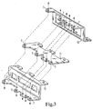
- FIG. 3 From Figure 3 are still different embodiments of holding parts 10, 11 and 12 can be seen, which also all have the mechanical standard interface with the receiving holes 7 for the fasteners 4 of Figures 1 and 2.
- fasteners 4 rivet joints, welded nuts, threaded bolts or other screw shapes can be used in all embodiments.
Landscapes
- Engineering & Computer Science (AREA)
- Microelectronics & Electronic Packaging (AREA)
- Connection Of Plates (AREA)
- Casings For Electric Apparatus (AREA)
- Fittings On The Vehicle Exterior For Carrying Loads, And Devices For Holding Or Mounting Articles (AREA)
- Mounting Of Printed Circuit Boards And The Like (AREA)
Claims (3)
- Dispositif de fixation d'un appareil électrique (1) comportant au moins un élément de fixation (4), ancré sur la partie (6 ; 10 ; 11 ; 12) portant l'appareil électrique (1) et dans le boîtier (2) de l'appareil électrique (1),
caractérisé en ce que
sur le boîtier (2) et sur la partie (6 ; 10 ; 11 ; 12) portant le boîtier (2), on réalise une répartition géométrique concordante des équipements (5, 7) pour recevoir les éléments de fixation (4) de manière à ce que, sur le boîtier (2), les équipements (5) ne se trouvent face qu'à une partie des équipements (7) sur la partie portante (6 ; 10 ; 11 ; 12) en position montée et qu'une partie des équipements (7) sur la partie portante (6 ; 10 ; 11 ; 12) ne soit pas utilisée de sorte que la partie portante (6 ; 10 ; 11 ; 12) constitue une interface mécanique standard permettant de fixer un boîtier (2) de taille différente de l'appareil électrique (1). - Dispositif de fixation selon la revendication 1,
caractérisé en ce que
les équipements sur le boîtier (2) sont des dômes de vissage (5) dans lesquels on visse les vis auto-taraudeuses (4) en tant qu'éléments de fixation. - Dispositif de fixation selon la revendication 1,
caractérisé en ce que
le boîtier (2) contient un appareil de commande électrique, pour un dispositif électromécanique ou électronique d'un véhicule automobile, les pièces de commutation de l'appareil de commande, en particulier la plaque de circuit imprimé, étant maintenues sur le boîtier (2) par des fixations séparées des éléments de fixation (4) pour l'attache sur la partie portante (6).
Applications Claiming Priority (3)
| Application Number | Priority Date | Filing Date | Title |
|---|---|---|---|
| DE10151689A DE10151689A1 (de) | 2001-10-19 | 2001-10-19 | Befestigungsvorrichtung für ein elektrisches Gerät |
| DE10151689 | 2001-10-19 | ||
| PCT/DE2002/003312 WO2003037686A1 (fr) | 2001-10-19 | 2002-09-06 | Dispositif de fixation destine a un appareil electrique |
Publications (2)
| Publication Number | Publication Date |
|---|---|
| EP1439984A1 EP1439984A1 (fr) | 2004-07-28 |
| EP1439984B1 true EP1439984B1 (fr) | 2006-11-22 |
Family
ID=7703073
Family Applications (1)
| Application Number | Title | Priority Date | Filing Date |
|---|---|---|---|
| EP02772048A Expired - Lifetime EP1439984B1 (fr) | 2001-10-19 | 2002-09-06 | Dispositif de fixation destine a un appareil electrique |
Country Status (6)
| Country | Link |
|---|---|
| US (1) | US20040262471A1 (fr) |
| EP (1) | EP1439984B1 (fr) |
| JP (1) | JP2005506928A (fr) |
| DE (2) | DE10151689A1 (fr) |
| ES (1) | ES2274097T3 (fr) |
| WO (1) | WO2003037686A1 (fr) |
Families Citing this family (4)
| Publication number | Priority date | Publication date | Assignee | Title |
|---|---|---|---|---|
| DE102014204836B4 (de) * | 2014-02-20 | 2020-07-02 | Ovalo Gmbh | Aktives Fahrwerk für ein Kraftfahrzeug |
| KR101735731B1 (ko) * | 2015-12-09 | 2017-05-15 | 현대오트론 주식회사 | 리벳 고정구를 구비한 전자제어장치 |
| US11277927B2 (en) * | 2019-11-05 | 2022-03-15 | Lear Corporation | System and method for mounting an electronics arrangement |
| DE102021208198A1 (de) | 2021-07-29 | 2023-02-02 | Robert Bosch Gesellschaft mit beschränkter Haftung | Elektrische Vorrichtung und elektrische Vorrichtungsfamilie |
Family Cites Families (13)
| Publication number | Priority date | Publication date | Assignee | Title |
|---|---|---|---|---|
| US4569458A (en) * | 1981-09-14 | 1986-02-11 | Horsley Larry L | Mounting for electrical outlet box |
| US4461593A (en) * | 1982-03-19 | 1984-07-24 | Illinois Tool Works Inc. | Self-aligning mounting arrangement |
| DE8312541U1 (de) * | 1983-04-28 | 1986-05-22 | Telefunken Fernseh Und Rundfunk Gmbh, 3000 Hannover | Anordnung zur Befestigung der Bildröhre in einem Fernsehempfänger |
| US4967990A (en) * | 1989-01-26 | 1990-11-06 | B-Line Systems, Inc. | Support for an electrical box |
| US5189358A (en) * | 1991-05-07 | 1993-02-23 | Fujitsu Limited | Adaptor for mounting portable radio apparatus to moving body and charger for portable radio apparatus |
| US5505483A (en) * | 1993-04-28 | 1996-04-09 | Nippondenso Co., Ltd. | Airbag safety module for vehicle |
| US6093977A (en) * | 1997-06-17 | 2000-07-25 | Mazda Motor Corporation | Vehicle electronic equipment apparatus and its assembling method |
| DE19801006A1 (de) * | 1998-01-14 | 1999-07-22 | Telefunken Microelectron | Gehäuse mit Stecker |
| JP4221511B2 (ja) * | 1998-11-26 | 2009-02-12 | 株式会社デンソー | 電子制御装置一体型油圧制御装置及びその組み付け方法 |
| DE29903003U1 (de) * | 1999-02-19 | 1999-05-20 | May & Steffens GmbH & Co. KG Elektrotechnische Fabrik, 50259 Pulheim | Elektrisches Gerät mit Tragelement |
| DE10105292B4 (de) * | 2000-02-09 | 2005-12-15 | Denso Corp., Kariya | Zentrale Fahrzeug-Baugruppen-Anbringungsstruktur mit elektrischem Anschluss |
| US6384334B1 (en) * | 2000-09-11 | 2002-05-07 | Ronald D. Webb | Electrical junction box and support bracket having sliding attachment |
| DE10126189C2 (de) * | 2001-05-30 | 2003-12-18 | Bosch Gmbh Robert | Gehäuse für ein elektrisches Gerät, insbesondere ein Schalt-oder Steuergerät in einem KFZ |
-
2001
- 2001-10-19 DE DE10151689A patent/DE10151689A1/de not_active Withdrawn
-
2002
- 2002-09-06 EP EP02772048A patent/EP1439984B1/fr not_active Expired - Lifetime
- 2002-09-06 JP JP2003539987A patent/JP2005506928A/ja active Pending
- 2002-09-06 ES ES02772048T patent/ES2274097T3/es not_active Expired - Lifetime
- 2002-09-06 DE DE50208806T patent/DE50208806D1/de not_active Expired - Lifetime
- 2002-09-06 WO PCT/DE2002/003312 patent/WO2003037686A1/fr not_active Ceased
- 2002-09-06 US US10/492,702 patent/US20040262471A1/en not_active Abandoned
Also Published As
| Publication number | Publication date |
|---|---|
| ES2274097T3 (es) | 2007-05-16 |
| EP1439984A1 (fr) | 2004-07-28 |
| DE50208806D1 (de) | 2007-01-04 |
| JP2005506928A (ja) | 2005-03-10 |
| US20040262471A1 (en) | 2004-12-30 |
| WO2003037686A1 (fr) | 2003-05-08 |
| DE10151689A1 (de) | 2003-04-30 |
Similar Documents
| Publication | Publication Date | Title |
|---|---|---|
| EP3977830B1 (fr) | Unité d'électronique de puissance comprenant au moins un module semi-conducteur raccordé au moyen d'un support en matière synthétique | |
| DE69517997T2 (de) | Luftfahrttechnische schnittstellenverteilereinheit | |
| DE69400534T2 (de) | Verbindungsstruktur zum elektrischen Verbinden von Elektromotor und Motorregeleinheit | |
| EP1675249B1 (fr) | Moteur électrique | |
| DE102005044867B4 (de) | Kombiniertes Befestigungs- und Kontaktierungssystem für elektrische Bauelemente auf übereinander angeordneten Leiterplatten | |
| EP0853022B1 (fr) | Module de fonction pour véhicule. | |
| EP1245933A2 (fr) | Dispositif électromécanique pour le montage d' un équipement électronique sur un support, en particulier pour le montage d' un instrument indicateur encastré dans un tableau de bord | |
| DE102013208984B4 (de) | Steuergerät | |
| DE102016224465B4 (de) | Elektronische Steuereinheit, die über eine Nietenbefestigung verfügt | |
| EP1439984B1 (fr) | Dispositif de fixation destine a un appareil electrique | |
| EP1921733B1 (fr) | Moteur triphasé et dispositif de commande | |
| DE202020101244U1 (de) | Anschlussvorrichtung und elektromechanische Baugruppe | |
| DE4405578B4 (de) | Elektronische Baueinheit | |
| DE102006039961B3 (de) | Kühlanordnung für ein Computersystem und Unterstützungsvorrichtung | |
| EP3876355A1 (fr) | Dispositif de connexion et module électromécanique | |
| DE10122798C1 (de) | Kombinierte Steck- und Schraubverbindung | |
| DE102021211866B3 (de) | Befestigungsanordnung eines Gerätegehäuses eines Geräts an einem Fahrzeugblech eines Kraftfahrzeugs sowie Kraftfahrzeug und Gerät | |
| DE19952912C2 (de) | Leiterplattenanordnung | |
| DE102023005207B3 (de) | Baugruppe eines Fahrzeugs | |
| DE102007019097B4 (de) | Masseanschluss für elektronische Geräte | |
| EP4396466B1 (fr) | Agencement de fixation d'un boîtier d'appareil d'un appareil sur une tôle de véhicule d'un véhicule à moteur ainsi que véhicule à moteur et appareil | |
| DE102012108859B4 (de) | Elektronikmodul | |
| DE20019537U1 (de) | Gehäuse für Leiterplatten | |
| EP1049215A2 (fr) | Connecteur électrique à fiche à angles multiples | |
| DE102019100051B4 (de) | Bauraumreduziertes Steckverbindergehäuse, Steckverbinderflansch sowie Steckverbindungssystem |
Legal Events
| Date | Code | Title | Description |
|---|---|---|---|
| PUAI | Public reference made under article 153(3) epc to a published international application that has entered the european phase |
Free format text: ORIGINAL CODE: 0009012 |
|
| 17P | Request for examination filed |
Effective date: 20040519 |
|
| AK | Designated contracting states |
Kind code of ref document: A1 Designated state(s): AT BE BG CH CY CZ DE DK EE ES FI FR GB GR IE IT LI LU MC NL PT SE SK TR |
|
| 17Q | First examination report despatched |
Effective date: 20040730 |
|
| GRAP | Despatch of communication of intention to grant a patent |
Free format text: ORIGINAL CODE: EPIDOSNIGR1 |
|
| GRAS | Grant fee paid |
Free format text: ORIGINAL CODE: EPIDOSNIGR3 |
|
| GRAA | (expected) grant |
Free format text: ORIGINAL CODE: 0009210 |
|
| AK | Designated contracting states |
Kind code of ref document: B1 Designated state(s): DE ES FR |
|
| REF | Corresponds to: |
Ref document number: 50208806 Country of ref document: DE Date of ref document: 20070104 Kind code of ref document: P |
|
| REG | Reference to a national code |
Ref country code: ES Ref legal event code: FG2A Ref document number: 2274097 Country of ref document: ES Kind code of ref document: T3 |
|
| ET | Fr: translation filed | ||
| PLBE | No opposition filed within time limit |
Free format text: ORIGINAL CODE: 0009261 |
|
| STAA | Information on the status of an ep patent application or granted ep patent |
Free format text: STATUS: NO OPPOSITION FILED WITHIN TIME LIMIT |
|
| 26N | No opposition filed |
Effective date: 20070823 |
|
| PGFP | Annual fee paid to national office [announced via postgrant information from national office to epo] |
Ref country code: ES Payment date: 20120924 Year of fee payment: 11 |
|
| PGFP | Annual fee paid to national office [announced via postgrant information from national office to epo] |
Ref country code: DE Payment date: 20121122 Year of fee payment: 11 Ref country code: FR Payment date: 20121008 Year of fee payment: 11 |
|
| REG | Reference to a national code |
Ref country code: DE Ref legal event code: R119 Ref document number: 50208806 Country of ref document: DE Effective date: 20140401 |
|
| REG | Reference to a national code |
Ref country code: FR Ref legal event code: ST Effective date: 20140530 |
|
| PG25 | Lapsed in a contracting state [announced via postgrant information from national office to epo] |
Ref country code: DE Free format text: LAPSE BECAUSE OF NON-PAYMENT OF DUE FEES Effective date: 20140401 Ref country code: FR Free format text: LAPSE BECAUSE OF NON-PAYMENT OF DUE FEES Effective date: 20130930 |
|
| REG | Reference to a national code |
Ref country code: ES Ref legal event code: FD2A Effective date: 20141007 |
|
| PG25 | Lapsed in a contracting state [announced via postgrant information from national office to epo] |
Ref country code: ES Free format text: LAPSE BECAUSE OF NON-PAYMENT OF DUE FEES Effective date: 20130907 |