EP1441318A2 - Système de sécurité - Google Patents
Système de sécurité Download PDFInfo
- Publication number
- EP1441318A2 EP1441318A2 EP04001193A EP04001193A EP1441318A2 EP 1441318 A2 EP1441318 A2 EP 1441318A2 EP 04001193 A EP04001193 A EP 04001193A EP 04001193 A EP04001193 A EP 04001193A EP 1441318 A2 EP1441318 A2 EP 1441318A2
- Authority
- EP
- European Patent Office
- Prior art keywords
- security system
- location
- imaging
- detected
- receiving
- Prior art date
- Legal status (The legal status is an assumption and is not a legal conclusion. Google has not performed a legal analysis and makes no representation as to the accuracy of the status listed.)
- Granted
Links
Images


Classifications
-
- G—PHYSICS
- G08—SIGNALLING
- G08B—SIGNALLING SYSTEMS, e.g. PERSONAL CALLING SYSTEMS; ORDER TELEGRAPHS; ALARM SYSTEMS
- G08B13/00—Burglar, theft or intruder alarms
- G08B13/18—Actuation by interference with heat, light, or radiation of shorter wavelength; Actuation by intruding sources of heat, light, or radiation of shorter wavelength
- G08B13/189—Actuation by interference with heat, light, or radiation of shorter wavelength; Actuation by intruding sources of heat, light, or radiation of shorter wavelength using passive radiation detection systems
- G08B13/194—Actuation by interference with heat, light, or radiation of shorter wavelength; Actuation by intruding sources of heat, light, or radiation of shorter wavelength using passive radiation detection systems using image scanning and comparing systems
- G08B13/196—Actuation by interference with heat, light, or radiation of shorter wavelength; Actuation by intruding sources of heat, light, or radiation of shorter wavelength using passive radiation detection systems using image scanning and comparing systems using television cameras
- G08B13/19678—User interface
- G08B13/19691—Signalling events for better perception by user, e.g. indicating alarms by making display brighter, adding text, creating a sound
-
- G—PHYSICS
- G08—SIGNALLING
- G08B—SIGNALLING SYSTEMS, e.g. PERSONAL CALLING SYSTEMS; ORDER TELEGRAPHS; ALARM SYSTEMS
- G08B13/00—Burglar, theft or intruder alarms
- G08B13/18—Actuation by interference with heat, light, or radiation of shorter wavelength; Actuation by intruding sources of heat, light, or radiation of shorter wavelength
- G08B13/181—Actuation by interference with heat, light, or radiation of shorter wavelength; Actuation by intruding sources of heat, light, or radiation of shorter wavelength using active radiation detection systems
- G08B13/187—Actuation by interference with heat, light, or radiation of shorter wavelength; Actuation by intruding sources of heat, light, or radiation of shorter wavelength using active radiation detection systems by interference of a radiation field
-
- G—PHYSICS
- G08—SIGNALLING
- G08B—SIGNALLING SYSTEMS, e.g. PERSONAL CALLING SYSTEMS; ORDER TELEGRAPHS; ALARM SYSTEMS
- G08B13/00—Burglar, theft or intruder alarms
- G08B13/18—Actuation by interference with heat, light, or radiation of shorter wavelength; Actuation by intruding sources of heat, light, or radiation of shorter wavelength
- G08B13/189—Actuation by interference with heat, light, or radiation of shorter wavelength; Actuation by intruding sources of heat, light, or radiation of shorter wavelength using passive radiation detection systems
- G08B13/194—Actuation by interference with heat, light, or radiation of shorter wavelength; Actuation by intruding sources of heat, light, or radiation of shorter wavelength using passive radiation detection systems using image scanning and comparing systems
- G08B13/196—Actuation by interference with heat, light, or radiation of shorter wavelength; Actuation by intruding sources of heat, light, or radiation of shorter wavelength using passive radiation detection systems using image scanning and comparing systems using television cameras
- G08B13/19602—Image analysis to detect motion of the intruder, e.g. by frame subtraction
- G08B13/19608—Tracking movement of a target, e.g. by detecting an object predefined as a target, using target direction and or velocity to predict its new position
-
- G—PHYSICS
- G08—SIGNALLING
- G08B—SIGNALLING SYSTEMS, e.g. PERSONAL CALLING SYSTEMS; ORDER TELEGRAPHS; ALARM SYSTEMS
- G08B13/00—Burglar, theft or intruder alarms
- G08B13/18—Actuation by interference with heat, light, or radiation of shorter wavelength; Actuation by intruding sources of heat, light, or radiation of shorter wavelength
- G08B13/189—Actuation by interference with heat, light, or radiation of shorter wavelength; Actuation by intruding sources of heat, light, or radiation of shorter wavelength using passive radiation detection systems
- G08B13/194—Actuation by interference with heat, light, or radiation of shorter wavelength; Actuation by intruding sources of heat, light, or radiation of shorter wavelength using passive radiation detection systems using image scanning and comparing systems
- G08B13/196—Actuation by interference with heat, light, or radiation of shorter wavelength; Actuation by intruding sources of heat, light, or radiation of shorter wavelength using passive radiation detection systems using image scanning and comparing systems using television cameras
- G08B13/19695—Arrangements wherein non-video detectors start video recording or forwarding but do not generate an alarm themselves
-
- G—PHYSICS
- G08—SIGNALLING
- G08B—SIGNALLING SYSTEMS, e.g. PERSONAL CALLING SYSTEMS; ORDER TELEGRAPHS; ALARM SYSTEMS
- G08B13/00—Burglar, theft or intruder alarms
- G08B13/22—Electrical actuation
- G08B13/24—Electrical actuation by interference with electromagnetic field distribution
- G08B13/2491—Intrusion detection systems, i.e. where the body of an intruder causes the interference with the electromagnetic field
-
- H—ELECTRICITY
- H05—ELECTRIC TECHNIQUES NOT OTHERWISE PROVIDED FOR
- H05B—ELECTRIC HEATING; ELECTRIC LIGHT SOURCES NOT OTHERWISE PROVIDED FOR; CIRCUIT ARRANGEMENTS FOR ELECTRIC LIGHT SOURCES, IN GENERAL
- H05B47/00—Circuit arrangements for operating light sources in general, i.e. where the type of light source is not relevant
- H05B47/10—Controlling the light source
- H05B47/105—Controlling the light source in response to determined parameters
- H05B47/115—Controlling the light source in response to determined parameters by determining the presence or movement of objects or living beings
- H05B47/125—Controlling the light source in response to determined parameters by determining the presence or movement of objects or living beings by using cameras
-
- Y—GENERAL TAGGING OF NEW TECHNOLOGICAL DEVELOPMENTS; GENERAL TAGGING OF CROSS-SECTIONAL TECHNOLOGIES SPANNING OVER SEVERAL SECTIONS OF THE IPC; TECHNICAL SUBJECTS COVERED BY FORMER USPC CROSS-REFERENCE ART COLLECTIONS [XRACs] AND DIGESTS
- Y02—TECHNOLOGIES OR APPLICATIONS FOR MITIGATION OR ADAPTATION AGAINST CLIMATE CHANGE
- Y02B—CLIMATE CHANGE MITIGATION TECHNOLOGIES RELATED TO BUILDINGS, e.g. HOUSING, HOUSE APPLIANCES OR RELATED END-USER APPLICATIONS
- Y02B20/00—Energy efficient lighting technologies, e.g. halogen lamps or gas discharge lamps
- Y02B20/40—Control techniques providing energy savings, e.g. smart controller or presence detection
Definitions
- FIG. 1 shows the configuration of the system according to this embodiment which installs a radar device 1 and an imaging device 2 in a building to detect and image an intruder or runaway.
- the moving device 3 is a means for moving the imaging device 2 up, down, right and left. It can move the imaging device 2 toward the direction of the object detected by the radar device by means of the control device 4 which will be described in the following paragraph.
- Any means can be applied to a radar device 1 as long as the means can detect an object's speed and location.
- a monopulse system in which an electric wave is sent by one transmission antenna and is received by two receiving antennas thereby detecting the azimuth of a target is most suitable because it makes it possible to monitor a wide area and detect a plurality of targets by means of one transmission antenna.
- This monopulse radar device enables a wide-angled area of 100 degrees to be monitored by one transmission antenna.
- the antenna portion consists of a transmission antenna 16 and two receiving antennas 17(a), 17(b).
- the transmission antenna 16 transmits a millimeter-wave band high-frequency signal sent by a transmitter 18 at a frequency according to the modulation signal from the modulator 19.
- Two receiving antennas 17(a), 17(b) receive the electric wave signal which was reflected by an object located in the area where the electric wave was transmitted and a mixer circuit 20 converts the frequency.
- the mixer circuit 20 also receives a signal from the transmitter 18, and therefore, a low-frequency signal generated as the result of the mixture of two signals is outputted to an analog circuit 21.
- the signal is amplified by the analog circuit 21 and outputted, and is then converted into a digital signal by an A/D converter 22.
- the signal is sent to the FFT processing unit 23.
- the FFT processing unit 23 applies the Fast Fourier Transform (FFT) to measure the signal's frequency spectrum as information of amplitude and phase and sends the data to a signal processing unit 24.
- FFT Fast Fourier Transform
- the signal processing unit 24 Based on the data in the frequency area obtained by the FFT processing unit 23, the signal processing unit 24 calculates the distance and relative speed and outputs the data as a measured distance value and a measured relative speed value.
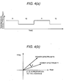
- 2-frequency CW Continuous Wave
- a modulation signal is inputted into the transmitter 18 and two frequencies f1, f2 are alternately transmitted with time intervals as shown in FIG.4 (a).
- An electric wave transmitted by the transmission antenna 16 is reflected by an object in front and the reflected signal is received by two receiving antennas 17(a), 17(b).
- the mixer circuit 20 mixes the received signal with a signal sent by the transmitter 18 and obtains a beat signal.
- f c denotes carrier frequency
- v denotes relative speed
- c denotes light velocity
- the intrusion determination unit 31 excludes an object 100 detected by the radar device 1 if its direction of travel is definitely away from the area in which no intrusion is permitted. That is, in this embodiment, an explanation is provided about the situation where an object 100 approaching a building should be alerted.
- a radar device is assumed to be installed in a building, and the relative speed of an object in a direction going away from the building is assumed to be positive. If relative speed v of the object is detected as being positive for a time period longer than the prescribed time T, it is determined that this object is moving away from the building and therefore, this object is excluded from intruder candidates.
- the intrusion determination unit 31 determines that the detected object 100 is an intruder candidate, the location information converting unit 32 estimates the location on the screen image captured by the imaging device 2 according to the location information (r, ⁇ ) detected by the radar device 1.
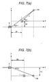
- a magnification of zoom is calculated so that the zoom function control unit 33 can control the lens moving device 11 to enlarge or reduce the size of the screen. Furthermore, the direction is calculated to coincide the direction of the imaging device 2 with the direction of the object so that the moving device control unit 34 can control the moving device 3 to adjust the direction of the imaging device 2. The procedure for calculating the magnification of zoom and the direction to move the imaging device 2 will be explained by referring to FIG.8.
- step 41 rotation angle ⁇ 2 for rotating the imaging device 2 in the vertical direction is calculated.
- ⁇ 2 can be calculated by the following equation using the detected object's location P.
- step 42 a magnification of zoom in the imaging device 2 is calculated.
- R Xp 2 + Yp 2 + Zp 2
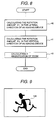
- K is a parameter determined by the specifications of the lens 10 and is defined beforehand by the following procedure.
- FIG.9 shows, the distance at which a picture of an object is recorded by the imaging device 2 installed in the building so that the picture shown on the monitor screen is large enough for the operator to identify the object as a person is calculated beforehand and the value is defined as K.
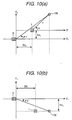
- the right-handed coordinate system in which the center of the luminous body 13 is the origin, the Z 1 -axis extends in the direction of the main axis of the luminous body 13 and the X 1 -axis and Y 1 -axis extend in parallel to the illuminating surface is defined as a light coordinate system X 1 -Y 1 -Z 1 , and the coordinates of the radar device 1 mounting position are expressed as (Xd 1 , Yd 1 , Zd 1 ).
- the object's location P 1 (Xp 1 , Yp 1 , Zp 1 ) in the light coordinate system is expressed by the following equation:
- intensity of light that illuminates the object is calculated so that light intensity control unit 35 can control the light-intensity adjusting device 14 to adjust the intensity of light. Furthermore, the direction is calculated to coincide the direction of the lighting device 5 with the direction of the object so that the direction control unit 36 can control the light moving device 15 to adjust the direction of the lighting device 5.
- the procedure for calculating light intensity and the direction to move the lighting device 5 will be explained by referring to FIG. 11.
- T is a parameter for controlling electric power to be supplied to the luminous body so that the function of the distance R 1 to the detected object can be established.
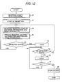
- the intrusion determination unit 31 determines that the detected object 100 is an intruder candidate, it transmits a signal to the data storing unit 39 to notify that the object 100 has been detected. Therefore, in step 46, the signal indicating that the radar device 1 has detected an object 100 is received, and is stored in step 47. In step 48, location information (r, ⁇ ) and the relative speed v of the object 100 detected by the radar device 1 and image information of the object 100 recorded by the imaging device 2 are received, and the information is then stored in step 49. In step 50, if the signal indicating that the radar device 1 had detected an object 100 has been received, the operation returns to step 48, and receipt and storage of the information is repeated.
- step 52 if the object detection signal has not been received, the counter number cnt is increased in step 53, and in step 54, while the cnt is smaller than time T, the operation returns to step 52 where the detection signal is repeatedly checked. Furthermore, in step 52, if the object detection signal is received, the operation returns to step 48, and subsequently, information is received and stored.
- step 54 when the cnt becomes equal to time T, the operation proceeds to step 55 and data storage stops.
- the data recording control unit 37 retrieves the above-mentioned image information and location information and transmits the information to the recording device 6.
- the recording device 6 stores the image information in an image memory such as a VTR and also stores information about the distance, angle and speed in the memory. This enables data to be recorded only when an intruding object 100 must be recorded, resulting in reduction of necessary storage capacity when compared to storage capacity required for recording on a steady basis.
- the send/receive control unit 38 retrieves the above-mentioned image information and location information and sends the information to the center 26 via the transmitting device 7.
- the above-mentioned data may be synthesized with a transmitted picture and stored as image information. Transmission of the location and speed information about the object 100 enables the indication of what distance from the building the intruder is approaching.
- the receiving device When the receiving device receives the signal in the center where an operator is standing by, the image information in chronological order is displayed on the display device 8. Simultaneously, the annunciation device 9 outputs an annunciation signal indicating that an object has been detected.
- a general annunciation signal uses sound to notify the operator; however, other methods may be utilized.
- the above-mentioned system eliminates the necessity for the operator to be constantly looking at the display device, resulting in a reduced burden on the operator. Furthermore, the operator can determine whether the detected object is an intruder or not by watching the screen of the display device instead of rushing to the site. As a result, even if the radar device 1 has mistakenly detected an object other than an intruder and transmitted the signal to the center, the operator does not have to rush to the site thereby reducing a burden on the operator.
- a security system which monitors an area around a building can track a detected intruder and accurately takes a picture of it. Furthermore, an operator can determine whether the detected object is an intruder or not without rushing to the site. Moreover, by broadening the beam width of the radar device, it is possible to reduce the number of radar devices while obtaining information about the entire monitoring area instead of alternately switching the radar devices or making the radar device rotating back and forth.
Landscapes
- Physics & Mathematics (AREA)
- General Physics & Mathematics (AREA)
- Engineering & Computer Science (AREA)
- Electromagnetism (AREA)
- Computer Vision & Pattern Recognition (AREA)
- Human Computer Interaction (AREA)
- Multimedia (AREA)
- Burglar Alarm Systems (AREA)
- Radar Systems Or Details Thereof (AREA)
- Alarm Systems (AREA)
Applications Claiming Priority (2)
| Application Number | Priority Date | Filing Date | Title |
|---|---|---|---|
| JP2003011741A JP3760918B2 (ja) | 2003-01-21 | 2003-01-21 | セキュリティシステム |
| JP2003011741 | 2003-01-21 |
Publications (3)
| Publication Number | Publication Date |
|---|---|
| EP1441318A2 true EP1441318A2 (fr) | 2004-07-28 |
| EP1441318A3 EP1441318A3 (fr) | 2004-12-08 |
| EP1441318B1 EP1441318B1 (fr) | 2008-07-23 |
Family
ID=32588606
Family Applications (1)
| Application Number | Title | Priority Date | Filing Date |
|---|---|---|---|
| EP04001193A Expired - Lifetime EP1441318B1 (fr) | 2003-01-21 | 2004-01-21 | Système de sécurité |
Country Status (4)
| Country | Link |
|---|---|
| US (1) | US7425983B2 (fr) |
| EP (1) | EP1441318B1 (fr) |
| JP (1) | JP3760918B2 (fr) |
| DE (1) | DE602004015172D1 (fr) |
Cited By (5)
| Publication number | Priority date | Publication date | Assignee | Title |
|---|---|---|---|---|
| FR2910161A1 (fr) * | 2006-12-15 | 2008-06-20 | Thales Sa | Systeme goniometrique de mini capteurs doppler en reseaux pour la surveillance de perimetres |
| WO2008094298A3 (fr) * | 2006-07-26 | 2009-08-06 | Gen Electric | Procédé et système de radiodétection et système de détection d'intrusion par télémétrie |
| EP2373128A3 (fr) * | 2010-03-30 | 2014-06-18 | Micas Ag | Dispositif d'éclairage de surfaces de voies de circulation |
| CN110278417A (zh) * | 2019-07-25 | 2019-09-24 | 上海莫吉娜智能信息科技有限公司 | 基于毫米波雷达的监控设备快速定位方法及系统 |
| CN110443984A (zh) * | 2019-06-27 | 2019-11-12 | 维沃移动通信有限公司 | 一种监控方法及移动终端 |
Families Citing this family (75)
| Publication number | Priority date | Publication date | Assignee | Title |
|---|---|---|---|---|
| JP2006071499A (ja) * | 2004-09-02 | 2006-03-16 | Sekisui Jushi Co Ltd | センシング手段及び接近警告システム |
| US9082456B2 (en) | 2005-01-31 | 2015-07-14 | The Invention Science Fund I Llc | Shared image device designation |
| US9489717B2 (en) | 2005-01-31 | 2016-11-08 | Invention Science Fund I, Llc | Shared image device |
| US20060170956A1 (en) | 2005-01-31 | 2006-08-03 | Jung Edward K | Shared image devices |
| US8902320B2 (en) | 2005-01-31 | 2014-12-02 | The Invention Science Fund I, Llc | Shared image device synchronization or designation |
| US9124729B2 (en) | 2005-01-31 | 2015-09-01 | The Invention Science Fund I, Llc | Shared image device synchronization or designation |
| US8606383B2 (en) | 2005-01-31 | 2013-12-10 | The Invention Science Fund I, Llc | Audio sharing |
| US9910341B2 (en) | 2005-01-31 | 2018-03-06 | The Invention Science Fund I, Llc | Shared image device designation |
| US20060174203A1 (en) | 2005-01-31 | 2006-08-03 | Searete Llc, A Limited Liability Corporation Of The State Of Delaware | Viewfinder for shared image device |
| JP4651068B2 (ja) * | 2005-02-07 | 2011-03-16 | 大同信号株式会社 | 2周波cwレーダ |
| US9942511B2 (en) | 2005-10-31 | 2018-04-10 | Invention Science Fund I, Llc | Preservation/degradation of video/audio aspects of a data stream |
| US9001215B2 (en) | 2005-06-02 | 2015-04-07 | The Invention Science Fund I, Llc | Estimating shared image device operational capabilities or resources |
| US10003762B2 (en) | 2005-04-26 | 2018-06-19 | Invention Science Fund I, Llc | Shared image devices |
| US9451200B2 (en) | 2005-06-02 | 2016-09-20 | Invention Science Fund I, Llc | Storage access technique for captured data |
| US9621749B2 (en) | 2005-06-02 | 2017-04-11 | Invention Science Fund I, Llc | Capturing selected image objects |
| US8964054B2 (en) | 2006-08-18 | 2015-02-24 | The Invention Science Fund I, Llc | Capturing selected image objects |
| US9819490B2 (en) | 2005-05-04 | 2017-11-14 | Invention Science Fund I, Llc | Regional proximity for shared image device(s) |
| US9191611B2 (en) | 2005-06-02 | 2015-11-17 | Invention Science Fund I, Llc | Conditional alteration of a saved image |
| US9967424B2 (en) | 2005-06-02 | 2018-05-08 | Invention Science Fund I, Llc | Data storage usage protocol |
| US20070008326A1 (en) * | 2005-06-02 | 2007-01-11 | Searete Llc, A Limited Liability Corporation Of The State Of Delaware | Dual mode image capture technique |
| US20070222865A1 (en) | 2006-03-15 | 2007-09-27 | Searete Llc, A Limited Liability Corporation Of The State Of Delaware | Enhanced video/still image correlation |
| US7991242B2 (en) | 2005-05-11 | 2011-08-02 | Optosecurity Inc. | Apparatus, method and system for screening receptacles and persons, having image distortion correction functionality |
| EP1886257A1 (fr) | 2005-05-11 | 2008-02-13 | Optosecurity Inc. | Procede et systeme d'inspection de bagages, de conteneurs de fret ou de personnes |
| JP3909370B2 (ja) * | 2005-08-04 | 2007-04-25 | オプテックス株式会社 | 防犯センサ |
| JP2007071605A (ja) * | 2005-09-05 | 2007-03-22 | Optex Co Ltd | 防犯センサ |
| US7321330B2 (en) | 2005-10-03 | 2008-01-22 | Sri Sports Limited | Ball measuring apparatus |
| US7304603B2 (en) * | 2006-02-17 | 2007-12-04 | Science, Engineering And Technology Associates Corporation | Radar apparatus and processing method for detecting human carried explosive devices |
| US7899232B2 (en) | 2006-05-11 | 2011-03-01 | Optosecurity Inc. | Method and apparatus for providing threat image projection (TIP) in a luggage screening system, and luggage screening system implementing same |
| JP5111795B2 (ja) * | 2006-06-29 | 2013-01-09 | 三菱電機株式会社 | 監視装置 |
| US8494210B2 (en) | 2007-03-30 | 2013-07-23 | Optosecurity Inc. | User interface for use in security screening providing image enhancement capabilities and apparatus for implementing same |
| JP5376777B2 (ja) * | 2007-06-13 | 2013-12-25 | 三菱電機株式会社 | レーダ装置 |
| JP5037279B2 (ja) * | 2007-09-19 | 2012-09-26 | 株式会社日立国際電気 | 監視装置 |
| JP5350721B2 (ja) * | 2008-09-09 | 2013-11-27 | 三菱電機エンジニアリング株式会社 | 居住者監視システムおよび居住者監視方法 |
| US8319833B2 (en) * | 2009-06-23 | 2012-11-27 | Sentrus, Inc. | Video surveillance system |
| CN101998046A (zh) * | 2009-08-21 | 2011-03-30 | 鸿富锦精密工业(深圳)有限公司 | 摄像装置及其调整方法 |
| KR101665388B1 (ko) * | 2011-01-20 | 2016-10-12 | 한화테크윈 주식회사 | 카메라 제어 방법 |
| US9111331B2 (en) | 2011-09-07 | 2015-08-18 | Rapiscan Systems, Inc. | X-ray inspection system that integrates manifest data with imaging/detection processing |
| JP2013250111A (ja) * | 2012-05-31 | 2013-12-12 | Ono Sokki Co Ltd | 音源探査装置 |
| JP6032163B2 (ja) * | 2013-09-11 | 2016-11-24 | トヨタ自動車株式会社 | 三次元物体認識装置、三次元物体認識方法、及び移動体 |
| KR101548168B1 (ko) * | 2014-01-15 | 2015-08-31 | 삼영이엔씨 (주) | 양식장 감시 시스템 |
| EP3809383B1 (fr) * | 2014-08-05 | 2023-12-27 | Sensormatic Electronics, LLC | Dispositif et procédé de conrtôle adaptatif d'un champ d'émetteur |
| US10620307B2 (en) * | 2015-11-04 | 2020-04-14 | University Of Hawaii | Systems and methods for detection of occupancy using radio waves |
| CN108232411A (zh) | 2015-11-05 | 2018-06-29 | 日本电产株式会社 | 缝隙阵列天线以及雷达装置 |
| WO2017078184A1 (fr) | 2015-11-05 | 2017-05-11 | Nidec Elesys Corporation | Antenne à fentes |
| DE102016125412B4 (de) | 2015-12-24 | 2023-08-17 | Nidec Elesys Corporation | Schlitz-Array-Antenne und Radar, Radarsystem sowie Drahtlos-Kommunikationssystem mit der Schlitz-Array-Antenne |
| DE102016125419B4 (de) | 2015-12-24 | 2022-10-20 | Nidec Elesys Corporation | Wellenleitervorrichtung, Schlitzantenne und Radar, Radarsystem sowie Drahtlos-Kommunikationssystem mit der Schlitzantenne |
| CN106981710B (zh) | 2016-01-15 | 2019-11-08 | 日本电产株式会社 | 波导装置、天线装置以及雷达 |
| WO2017131099A1 (fr) | 2016-01-29 | 2017-08-03 | Nidec Elesys Corporation | Dispositif de guidage d'onde, et dispositif d'antenne comprenant le dispositif de guidage d'onde |
| DE102017102284A1 (de) | 2016-02-08 | 2017-08-10 | Nidec Elesys Corporation | Wellenleitervorrichtung und Antennenvorrichtung mit der Wellenleitervorrichtung |
| DE102017102559A1 (de) | 2016-02-12 | 2017-08-17 | Nidec Elesys Corporation | Wellenleitervorrichtung und Antennenvorrichtung mit der Wellenleitervorrichtung |
| PL3764281T3 (pl) | 2016-02-22 | 2025-02-10 | Rapiscan Systems, Inc. | Sposoby identyfikacji broni palnej na obrazach radiograficznych |
| JP2019047141A (ja) | 2016-03-29 | 2019-03-22 | 日本電産エレシス株式会社 | マイクロ波ic導波路装置モジュール、レーダ装置およびレーダシステム |
| CN107275802B (zh) | 2016-04-05 | 2020-08-18 | 日本电产株式会社 | 天线阵列 |
| JP2019054315A (ja) | 2016-04-28 | 2019-04-04 | 日本電産エレシス株式会社 | 実装基板、導波路モジュール、集積回路実装基板、マイクロ波モジュール、レーダ装置およびレーダシステム |
| JP2018164252A (ja) | 2017-03-24 | 2018-10-18 | 日本電産株式会社 | スロットアレーアンテナ、および当該スロットアレーアンテナを備えるレーダ |
| US20180276842A1 (en) * | 2017-03-27 | 2018-09-27 | Blackberry Limited | System and method for image based confirmation |
| CN108695585B (zh) | 2017-04-12 | 2021-03-16 | 日本电产株式会社 | 高频构件的制造方法 |
| JP7020677B2 (ja) | 2017-04-13 | 2022-02-16 | 日本電産エレシス株式会社 | スロットアンテナ装置 |
| US10608345B2 (en) | 2017-04-13 | 2020-03-31 | Nidec Corporation | Slot array antenna |
| CN108736166B (zh) | 2017-04-14 | 2020-11-13 | 日本电产株式会社 | 缝隙天线装置以及雷达装置 |
| WO2018207838A1 (fr) | 2017-05-11 | 2018-11-15 | Nidec Corporation | Dispositif de guide d'ondes, et dispositif d'antenne comprenant le dispositif de guide d'ondes |
| WO2018207796A1 (fr) | 2017-05-11 | 2018-11-15 | Nidec Corporation | Dispositif de guide d'ondes, et dispositif d'antenne comprenant le dispositif de guide d'ondes |
| US10547122B2 (en) | 2017-06-26 | 2020-01-28 | Nidec Corporation | Method of producing a horn antenna array and antenna array |
| JP7103860B2 (ja) | 2017-06-26 | 2022-07-20 | 日本電産エレシス株式会社 | ホーンアンテナアレイ |
| JP2019009779A (ja) | 2017-06-26 | 2019-01-17 | 株式会社Wgr | 伝送線路装置 |
| DE102018115610A1 (de) | 2017-06-30 | 2019-01-03 | Nidec Corporation | Wellenleitervorrichtungsmodul, Mikrowellenmodul, Radarvorrichtung und Radarsystem |
| JP7294608B2 (ja) | 2017-08-18 | 2023-06-20 | ニデックエレシス株式会社 | アンテナアレイ |
| JP2019050568A (ja) | 2017-09-07 | 2019-03-28 | 日本電産株式会社 | 方向性結合器 |
| DE102018124924A1 (de) | 2017-10-10 | 2019-04-11 | Nidec Corporation | Wellenleitende Vorrichtung |
| JP7298808B2 (ja) | 2018-06-14 | 2023-06-27 | ニデックエレシス株式会社 | スロットアレイアンテナ |
| CN111446530A (zh) | 2019-01-16 | 2020-07-24 | 日本电产株式会社 | 波导装置、电磁波锁定装置、天线装置以及雷达装置 |
| JP2020149158A (ja) * | 2019-03-11 | 2020-09-17 | Necエンベデッドプロダクツ株式会社 | 防犯装置、防犯方法、プログラム |
| US10855929B1 (en) * | 2019-06-27 | 2020-12-01 | Guangdong Outdoor Technology Limited. | Monitoring method of monitoring camera and monitoring camera |
| CN112217966B (zh) * | 2019-07-12 | 2022-04-26 | 杭州海康威视数字技术股份有限公司 | 监控装置 |
| CN115174872A (zh) * | 2022-09-08 | 2022-10-11 | 云丁网络技术(北京)有限公司 | 一种监控方法及装置 |
Family Cites Families (16)
| Publication number | Priority date | Publication date | Assignee | Title |
|---|---|---|---|---|
| GB1357457A (en) | 1972-03-20 | 1974-06-19 | Mullard Ltd | Doppler radar system |
| JPS61246685A (ja) | 1985-04-25 | 1986-11-01 | Ishikawajima Harima Heavy Ind Co Ltd | 衝突物捕捉映像装置 |
| JPS62121523U (fr) * | 1986-01-24 | 1987-08-01 | ||
| US5473368A (en) * | 1988-11-29 | 1995-12-05 | Hart; Frank J. | Interactive surveillance device |
| GB2250156B (en) | 1990-10-06 | 1994-04-06 | Chubb Electronics Ltd | Video surveillance system |
| JPH05180936A (ja) | 1992-01-08 | 1993-07-23 | Japan Radio Co Ltd | 夜間航海支援装置 |
| FR2700046B1 (fr) | 1992-12-30 | 1995-03-17 | Hymatom | Dispositif de transmission d'images d'un site protégé. |
| AUPN374495A0 (en) * | 1995-06-23 | 1995-07-13 | Vision Systems Limited | Security sensor arrangement |
| DE19710727A1 (de) | 1997-03-14 | 1998-09-17 | Sick Ag | Überwachungseinrichtung |
| EP0899580A3 (fr) | 1997-08-29 | 2000-02-02 | Kabushiki Kaisha Toshiba | Système de localisation de cible et de guidage d'avion pour l'approche |
| JP2930236B1 (ja) * | 1998-01-26 | 1999-08-03 | 本田技研工業株式会社 | レーダ装置 |
| JP2000003478A (ja) | 1998-06-16 | 2000-01-07 | Mitsubishi Electric Corp | 動態検知装置 |
| JP2000338231A (ja) | 1999-05-31 | 2000-12-08 | Mitsubishi Electric Corp | 侵入者検知装置 |
| US6734911B1 (en) * | 1999-09-30 | 2004-05-11 | Koninklijke Philips Electronics N.V. | Tracking camera using a lens that generates both wide-angle and narrow-angle views |
| US6853809B2 (en) * | 2001-01-30 | 2005-02-08 | Koninklijke Philips Electronics N.V. | Camera system for providing instant switching between wide angle and full resolution views of a subject |
| US6400265B1 (en) * | 2001-04-24 | 2002-06-04 | Microstrategy, Inc. | System and method for monitoring security systems by using video images |
-
2003
- 2003-01-21 JP JP2003011741A patent/JP3760918B2/ja not_active Expired - Fee Related
-
2004
- 2004-01-13 US US10/755,293 patent/US7425983B2/en not_active Expired - Fee Related
- 2004-01-21 EP EP04001193A patent/EP1441318B1/fr not_active Expired - Lifetime
- 2004-01-21 DE DE602004015172T patent/DE602004015172D1/de not_active Expired - Fee Related
Cited By (7)
| Publication number | Priority date | Publication date | Assignee | Title |
|---|---|---|---|---|
| WO2008094298A3 (fr) * | 2006-07-26 | 2009-08-06 | Gen Electric | Procédé et système de radiodétection et système de détection d'intrusion par télémétrie |
| FR2910161A1 (fr) * | 2006-12-15 | 2008-06-20 | Thales Sa | Systeme goniometrique de mini capteurs doppler en reseaux pour la surveillance de perimetres |
| WO2008071780A3 (fr) * | 2006-12-15 | 2008-10-30 | Thales Sa | Systeme goniometrique de mini capteurs doppler en reseaux pour la surveillance de perimetres |
| EP2373128A3 (fr) * | 2010-03-30 | 2014-06-18 | Micas Ag | Dispositif d'éclairage de surfaces de voies de circulation |
| CN110443984A (zh) * | 2019-06-27 | 2019-11-12 | 维沃移动通信有限公司 | 一种监控方法及移动终端 |
| CN110278417A (zh) * | 2019-07-25 | 2019-09-24 | 上海莫吉娜智能信息科技有限公司 | 基于毫米波雷达的监控设备快速定位方法及系统 |
| CN110278417B (zh) * | 2019-07-25 | 2021-04-16 | 上海莫吉娜智能信息科技有限公司 | 基于毫米波雷达的监控设备快速定位方法及系统 |
Also Published As
| Publication number | Publication date |
|---|---|
| US7425983B2 (en) | 2008-09-16 |
| DE602004015172D1 (de) | 2008-09-04 |
| EP1441318A3 (fr) | 2004-12-08 |
| JP3760918B2 (ja) | 2006-03-29 |
| US20040141056A1 (en) | 2004-07-22 |
| JP2004227111A (ja) | 2004-08-12 |
| EP1441318B1 (fr) | 2008-07-23 |
Similar Documents
| Publication | Publication Date | Title |
|---|---|---|
| US7425983B2 (en) | Security system | |
| EP1326090A2 (fr) | Système de securité | |
| US7463182B1 (en) | Radar apparatus | |
| US7679562B2 (en) | Target detection apparatus and system | |
| US6127965A (en) | Method and apparatus for rejecting rain clutter in a radar system | |
| US6859164B2 (en) | Detecting system | |
| KR101187909B1 (ko) | 감시 카메라 시스템 | |
| KR20040019096A (ko) | 이동 전화 기지국에 의해 송신된 신호를 이용하는 수동형이동 물체 탐지 시스템 및 그 방법 | |
| US20060267764A1 (en) | Object detection sensor | |
| US20070176822A1 (en) | Target detection apparatus and system | |
| US8044839B2 (en) | Combined radar and communications link | |
| JP3527979B2 (ja) | マイクロウエーブセンサ | |
| JP2005295469A (ja) | 監視システム | |
| JP2003217099A (ja) | 車載型周辺監視装置 | |
| CN112859069A (zh) | 一种雷达安防监控方法及系统 | |
| US7218271B2 (en) | System and method for determining patrol speed | |
| JP4741365B2 (ja) | 物体検知センサ | |
| KR102228824B1 (ko) | 레이더 센서, 레이더 장치 및 레이더 지향점 조정 시스템 | |
| KR20100040822A (ko) | 주정차 위반차량 단속시스템 | |
| WO2021059340A1 (fr) | Système radar | |
| JP3324537B2 (ja) | 車両監視装置 | |
| JPH11272988A (ja) | 交通量調査装置 | |
| JP2025125277A (ja) | 監視システム | |
| JP2017181099A (ja) | 物体検知装置 | |
| JP7449443B2 (ja) | レーダーシステム及び物体検知方法 |
Legal Events
| Date | Code | Title | Description |
|---|---|---|---|
| PUAI | Public reference made under article 153(3) epc to a published international application that has entered the european phase |
Free format text: ORIGINAL CODE: 0009012 |
|
| AK | Designated contracting states |
Kind code of ref document: A2 Designated state(s): AT BE BG CH CY CZ DE DK EE ES FI FR GB GR HU IE IT LI LU MC NL PT RO SE SI SK TR |
|
| AX | Request for extension of the european patent |
Extension state: AL LT LV MK |
|
| PUAL | Search report despatched |
Free format text: ORIGINAL CODE: 0009013 |
|
| AK | Designated contracting states |
Kind code of ref document: A3 Designated state(s): AT BE BG CH CY CZ DE DK EE ES FI FR GB GR HU IE IT LI LU MC NL PT RO SE SI SK TR |
|
| AX | Request for extension of the european patent |
Extension state: AL LT LV MK |
|
| 17P | Request for examination filed |
Effective date: 20050330 |
|
| AKX | Designation fees paid |
Designated state(s): DE FR GB IT |
|
| 17Q | First examination report despatched |
Effective date: 20051117 |
|
| GRAP | Despatch of communication of intention to grant a patent |
Free format text: ORIGINAL CODE: EPIDOSNIGR1 |
|
| GRAS | Grant fee paid |
Free format text: ORIGINAL CODE: EPIDOSNIGR3 |
|
| GRAA | (expected) grant |
Free format text: ORIGINAL CODE: 0009210 |
|
| RAP1 | Party data changed (applicant data changed or rights of an application transferred) |
Owner name: HITACHI, LTD. |
|
| AK | Designated contracting states |
Kind code of ref document: B1 Designated state(s): DE FR GB IT |
|
| REG | Reference to a national code |
Ref country code: GB Ref legal event code: FG4D |
|
| REF | Corresponds to: |
Ref document number: 602004015172 Country of ref document: DE Date of ref document: 20080904 Kind code of ref document: P |
|
| PGFP | Annual fee paid to national office [announced via postgrant information from national office to epo] |
Ref country code: DE Payment date: 20090131 Year of fee payment: 6 |
|
| PLBE | No opposition filed within time limit |
Free format text: ORIGINAL CODE: 0009261 |
|
| STAA | Information on the status of an ep patent application or granted ep patent |
Free format text: STATUS: NO OPPOSITION FILED WITHIN TIME LIMIT |
|
| 26N | No opposition filed |
Effective date: 20090424 |
|
| PG25 | Lapsed in a contracting state [announced via postgrant information from national office to epo] |
Ref country code: IT Free format text: LAPSE BECAUSE OF FAILURE TO SUBMIT A TRANSLATION OF THE DESCRIPTION OR TO PAY THE FEE WITHIN THE PRESCRIBED TIME-LIMIT Effective date: 20080723 |
|
| GBPC | Gb: european patent ceased through non-payment of renewal fee |
Effective date: 20090121 |
|
| PGFP | Annual fee paid to national office [announced via postgrant information from national office to epo] |
Ref country code: FR Payment date: 20090121 Year of fee payment: 6 |
|
| PG25 | Lapsed in a contracting state [announced via postgrant information from national office to epo] |
Ref country code: GB Free format text: LAPSE BECAUSE OF NON-PAYMENT OF DUE FEES Effective date: 20090121 |
|
| REG | Reference to a national code |
Ref country code: FR Ref legal event code: ST Effective date: 20100930 |
|
| PG25 | Lapsed in a contracting state [announced via postgrant information from national office to epo] |
Ref country code: FR Free format text: LAPSE BECAUSE OF NON-PAYMENT OF DUE FEES Effective date: 20100201 |
|
| PG25 | Lapsed in a contracting state [announced via postgrant information from national office to epo] |
Ref country code: DE Free format text: LAPSE BECAUSE OF NON-PAYMENT OF DUE FEES Effective date: 20100803 |