EP1443577A1 - Pile à combustible - Google Patents
Pile à combustible Download PDFInfo
- Publication number
- EP1443577A1 EP1443577A1 EP03257009A EP03257009A EP1443577A1 EP 1443577 A1 EP1443577 A1 EP 1443577A1 EP 03257009 A EP03257009 A EP 03257009A EP 03257009 A EP03257009 A EP 03257009A EP 1443577 A1 EP1443577 A1 EP 1443577A1
- Authority
- EP
- European Patent Office
- Prior art keywords
- group
- fuel cell
- catalyst
- cell according
- particles
- Prior art date
- Legal status (The legal status is an assumption and is not a legal conclusion. Google has not performed a legal analysis and makes no representation as to the accuracy of the status listed.)
- Granted
Links
Images




Classifications
-
- H—ELECTRICITY
- H01—ELECTRIC ELEMENTS
- H01M—PROCESSES OR MEANS, e.g. BATTERIES, FOR THE DIRECT CONVERSION OF CHEMICAL ENERGY INTO ELECTRICAL ENERGY
- H01M4/00—Electrodes
- H01M4/86—Inert electrodes with catalytic activity, e.g. for fuel cells
- H01M4/96—Carbon-based electrodes
-
- H—ELECTRICITY
- H01—ELECTRIC ELEMENTS
- H01M—PROCESSES OR MEANS, e.g. BATTERIES, FOR THE DIRECT CONVERSION OF CHEMICAL ENERGY INTO ELECTRICAL ENERGY
- H01M4/00—Electrodes
- H01M4/86—Inert electrodes with catalytic activity, e.g. for fuel cells
- H01M4/8647—Inert electrodes with catalytic activity, e.g. for fuel cells consisting of more than one material, e.g. consisting of composites
- H01M4/8652—Inert electrodes with catalytic activity, e.g. for fuel cells consisting of more than one material, e.g. consisting of composites as mixture
-
- H—ELECTRICITY
- H01—ELECTRIC ELEMENTS
- H01M—PROCESSES OR MEANS, e.g. BATTERIES, FOR THE DIRECT CONVERSION OF CHEMICAL ENERGY INTO ELECTRICAL ENERGY
- H01M4/00—Electrodes
- H01M4/86—Inert electrodes with catalytic activity, e.g. for fuel cells
- H01M4/90—Selection of catalytic material
- H01M4/9075—Catalytic material supported on carriers, e.g. powder carriers
- H01M4/9083—Catalytic material supported on carriers, e.g. powder carriers on carbon or graphite
-
- H—ELECTRICITY
- H01—ELECTRIC ELEMENTS
- H01M—PROCESSES OR MEANS, e.g. BATTERIES, FOR THE DIRECT CONVERSION OF CHEMICAL ENERGY INTO ELECTRICAL ENERGY
- H01M4/00—Electrodes
- H01M4/86—Inert electrodes with catalytic activity, e.g. for fuel cells
- H01M4/90—Selection of catalytic material
- H01M4/92—Metals of platinum group
-
- H—ELECTRICITY
- H01—ELECTRIC ELEMENTS
- H01M—PROCESSES OR MEANS, e.g. BATTERIES, FOR THE DIRECT CONVERSION OF CHEMICAL ENERGY INTO ELECTRICAL ENERGY
- H01M4/00—Electrodes
- H01M4/86—Inert electrodes with catalytic activity, e.g. for fuel cells
- H01M4/90—Selection of catalytic material
- H01M4/92—Metals of platinum group
- H01M4/925—Metals of platinum group supported on carriers, e.g. powder carriers
- H01M4/926—Metals of platinum group supported on carriers, e.g. powder carriers on carbon or graphite
-
- Y—GENERAL TAGGING OF NEW TECHNOLOGICAL DEVELOPMENTS; GENERAL TAGGING OF CROSS-SECTIONAL TECHNOLOGIES SPANNING OVER SEVERAL SECTIONS OF THE IPC; TECHNICAL SUBJECTS COVERED BY FORMER USPC CROSS-REFERENCE ART COLLECTIONS [XRACs] AND DIGESTS
- Y02—TECHNOLOGIES OR APPLICATIONS FOR MITIGATION OR ADAPTATION AGAINST CLIMATE CHANGE
- Y02E—REDUCTION OF GREENHOUSE GAS [GHG] EMISSIONS, RELATED TO ENERGY GENERATION, TRANSMISSION OR DISTRIBUTION
- Y02E60/00—Enabling technologies; Technologies with a potential or indirect contribution to GHG emissions mitigation
- Y02E60/30—Hydrogen technology
- Y02E60/50—Fuel cells
Definitions
- the present invention relates to a fuel cell that uses directly hydrogen, methanol, ethanol, dimethyl ether, isopropyl alcohol, ethylene glycol, glycerin, methane, dimethoxymethane and the like as a fuel and the air, oxygen or ozone as an oxidant.
- a fuel cell generates electric power by an electrochemical reaction between a fuel capable of generating a hydrogen ion such as hydrogen and an oxygen containing oxidant such as the air. Its structure will be described herein.
- catalyst layers are formed respectively on both surfaces of a polymer electrolyte for transporting hydrogen ions selectively.
- gas diffusion layers are formed using, for example, a water-repellent electrically conductive carbon particle paper that has both fuel gas permeability and electron conductivity.
- the catalyst layer and the gas diffusion layer form an electrode.
- a gas sealant or a gasket is disposed so as to surround the electrode and sandwich the polymer electrolyte so that a fuel to be supplied may not leak out and be mixed with the oxidant.
- This sealant or gasket is integrated with the electrode and the polymer electrolyte, thus forming a membrane electrode assembly (MEA).
- the catalyst layer of the fuel cell is produced by preparing a paste of a platinum-based precious metal catalyst as a catalyst with electrically conductive carbon particles such as carbon black or graphite (a catalyst carrier) and a polymer electrolyte, and forming a thin film of this paste.
- Nafion (trade name; manufactured by DuPont.), which is a perfluorocarbon sulfonic acid polymer, is in general use as the polymer electrolyte. In order to provide the “Nafion” with hydrogen ion conductivity, it is necessary to humidify it.
- the incoming fuel from an anode side is separated into hydrogen ions and electrons on the catalyst of the electrode, while hydrogen ions and electrons that have passed through the electrolyte react with the oxidant on the catalyst on a cathode side. At this time, electric energy can be obtained.
- the area of the three-phase zone is an effective area of the catalyst. As this area becomes larger, a utilization factor of the catalyst increases, leading to a higher cell performance. By including the polymer electrolyte in the catalyst layer as described above, the reaction area increases.
- a conventional technology has suggested a method of applying a dispersed solution of the polymer electrolyte and a mixture of catalyst onto a polymer electrolyte membrane and hot-pressing with an electrode, followed by reduction of the catalyst compound, and a method including the reduction, the application and then the hot-pressing (for example, see JP 62(1987)-61118 B and JP 62(1987)-61119 B).
- the above-mentioned conventional catalyst layer uses the polymer electrolyte that is soluble in water and an alcohol solution such as ethanol.
- the electrolyte elutes into water generated in the cathode during power generation and humidifying water necessary for hydrogen ion conduction, so that the three-phase zone decreases, lowering the voltage.
- the present invention provides a fuel cell using a thin film electrolyte that does not elute into water or alcohol, thereby achieving an increased area of a three-phase zone in a catalyst layer so as to obtain a long lifetime and high voltage.
- a fuel cell of the present invention is a fuel cell for generating an electric power by supplying one electrode with a fuel and the other electrode with an oxidant.
- the fuel cell includes a catalyst layer formed on at least one surface of at least one of the one electrode and the other electrode.
- the catalyst layer is a layer including catalyst particles alone, a layer including a mixture of the catalyst particles and other particles, or a layer of a porous film carrying at least the catalyst particles, and a molecule including an ion-conducting functional group serving as an electrolyte is chemically bonded to a surface of at least one selected from the group consisting of the catalyst particles, the other particles and the porous film.
- FIG. 1 is a schematic view showing a catalyst layer according to Example 1 of the present invention.
- FIG. 2 is a schematic plan view showing an electrolyte membrane electrode assembly (MEA) of a fuel cell according to Example 1 of the present invention.
- MEA electrolyte membrane electrode assembly
- FIG. 3 is a perspective view showing a structure of a unit cell of the fuel cell according to Example 1 of the present invention.
- FIG. 4 is a sectional view showing a stacked structure in which the unit cells of the fuel cell according to Example 1 of the present invention are stacked.
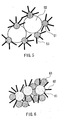
- FIG. 5 is a schematic view showing a catalyst layer according to Example 2 of the present invention.
- FIG. 6 is a schematic view showing a catalyst layer according to Example 3 of the present invention.
- FIG. 7 is a schematic view showing a catalyst layer according to Example 4 of the present invention.
- FIG. 8 is a schematic view showing an electrolyte membrane electrode assembly (MEA) according to Example 5 of the present invention.
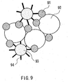
- FIG. 9 is a schematic view showing an electrolyte membrane electrode assembly (MEA) according to Example 6 of the present invention.
- FIG. 10 is a schematic plan view showing an electrolyte membrane electrode assembly (MEA) according to Example 7 of the present invention.
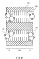
- FIG. 11 is a schematic plan view showing an electrolyte membrane electrode assembly (MEA) according to Example 8 of the present invention.
- the present invention relates to a fuel cell.
- its catalyst layer is a layer including catalyst particles alone, a layer including a mixture of the catalyst particles and other particles, or a layer of a porous film carrying at least the catalyst particles, and a molecule including an ion-conducting functional group serving as an electrolyte is chemically bonded to a surface of at least one selected from the group consisting of the catalyst particles, the other particles and the porous film.
- the ion-conducting functional group functions as an electrolyte.
- the chemical bond is any of a covalent bond, an ionic bond, a coordinate bond and a metallic bond.
- a covalent bond formed by an elimination reaction is preferable because it is the most stable in chemical and physical terms.
- the elimination reaction refers to dehydrohalogenation, dealcoholization (wherein the alcohol has 1 to 3 carbon atoms) or the like.
- the molecule including the ion-conducting functional group has a mean molecular weight of 40 to 10,000.
- the molecule including the ion-conducting functional group needs to be directly chemically-bonded to a substrate, and a molecular weight of at least 40 is necessary for the molecule to have a functional group needed for that chemical bond.
- the molecular weight exceeding 10,000 is not appropriate because such a large molecular weight makes it difficult to achieve a conformation that is most suitable for forming a molecular thin film, and thus, the molecule including the ion-conducting functional group cannot be bonded to the substrate suitably.
- TOF-SIMS Time-of-Flight Secondary Ion Mass Spectrometry
- the molecular thin film refers to a film formed by allowing an elimination reaction such as dehydrochlorination, dealcoholization or deisocyanation between a reactive group such as a chloro group, an alkoxyl group or an isocyanate group present at the end of a molecule and an active hydrogen (a hydroxyl group, a carboxyl group, an amino group, an imino group or the like) of a substrate, and a film obtained by a polymerization of the above film.
- an elimination reaction such as dehydrochlorination, dealcoholization or deisocyanation between a reactive group such as a chloro group, an alkoxyl group or an isocyanate group present at the end of a molecule and an active hydrogen (a hydroxyl group, a carboxyl group, an amino group, an imino group or the like) of a substrate, and a film obtained by a polymerization of the above film.
- the functional group at the end of the molecule is -SiCl 3 , -Si(OR) 3 (wherein R is an alkyl group having 1 to 3 carbon atoms) or -Si(NCO) 3
- R is an alkyl group having 1 to 3 carbon atoms
- -Si(NCO) 3 when an active hydrogen included in -OR group, -CHO group, -COOH group, -NH 2 group, >NH group or the like is present on the surface of the substrate or that of an underlying layer formed on the substrate, dehydrochlorination, dealcoholization or deisocyanation occurs so as to covalently-bond a chemisorbed molecule to the surface of the substrate or that of the underlying layer formed on the substrate.
- the molecular film formed by this method is called a "chemisorption film” or a “self assembling film.”
- unsaturated bonds are allowed to be present in the molecules in advance, and the molecules are polymerized by photopolymerization or the like after forming the chemisorption film.
- the molecule including the ion-conducting functional group includes at least one organic group selected from the group consisting of fluorocarbon and hydrocarbon.
- a fluorocarbon group ((CF 2 ) n -, wherein n ranges from 2 to 30) is preferable because it is sufficiently stable at high electric potentials that the molecule is not cleaved easily, the protons can pass through easily and the water molecules cannot pass through easily.
- the ion-conducting functional group is a proton dissociating functional group.
- the proton dissociating functional group is at least one functional group selected from the group consisting of a phosphonyl group, a phosphinyl group, a sulfonyl group, a sulfinic group, a sulfonic group and a carboxyl group.
- the ion-conducting functional group is a hydrogen bondable functional group. This allows proton conduction utilizing water molecules bonded to the hydrogen bondable functional group, so that an electrode catalyst reaction can be achieved.
- the hydrogen bondable functional group is at least one functional group selected from the group consisting of a mercapto group, an ether linkage group, a nitro group, a hydroxyl group, a quaternary ammonium base and an amino group.
- the chemical bond is at least one bond selected from the group consisting of a covalent bond, an ionic bond, a coordinate bond and a metallic bond. It is preferable that the chemical bond is a covalent bond formed by an elimination reaction. This is because the most stable bond can be achieved.
- the chemical bond is a bond via an oxygen atom.
- the chemical bond may be a bond via a nitrogen atom.
- an active hydrogen for example, a hydroxyl group (-OH), a carboxyl group (-COOH), an amino group (-NH 2 ), or an imino group (>NH), on the substrate surface.
- the catalyst particles include at least one selected from the group consisting of platinum, gold, palladium, nickel, rhodium, cobalt, iridium, osmium and iron. This is because they are an excellent oxidation catalyst.
- the catalyst layer further includes an electron conductor.
- the electron conductor is carbon, since carbon has an excellent electron conductivity and is electrochemically stable and its surface has a functional group to which the molecule including the ion-conducting functional group can be chemically bonded.
- the other particles are an inorganic substance.
- the inorganic substance includes at least one selected from the group consisting of silica, alumina, quartz, glass, ceramics and mica. This is because the surface of the inorganic substance has a functional group to which the molecule including the ion-conducting functional group can be chemically bonded, and in particular, the densities of the functional groups present on the surface of silica and alumina are higher than those of other inorganic substances.
- the ceramics may include glass, since there also are glassy ceramics such as porcelain and pottery.
- the inorganic substance is in the form of particles.
- the inorganic substance particles have a mean particle diameter ranging from 0.1 to 100 ⁇ m.
- the mean particle diameter exceeds 100 ⁇ m, the surface area of the inorganic substance particles is so small that the molecules having the ion-conducting functional group are sparse, lowering ion conductivity.
- the mean particle diameter is smaller than 0.1 ⁇ m, the inorganic substance particles are covered with the catalyst and the electron-conducting substances, so that ions cannot be conducted to the electrolyte part. Consequently, the cell voltage drops.
- the porous film has a porosity ranging from 5% to 95%.
- the porosity smaller than 5% lowers diffusibility of the fuel and products, so that power generation becomes difficult especially in a large current density region requiring a large amount of fuel (diffusion controlled).
- the porosity is larger than 95%, the electron movement between the electron-conducting substances and the ion conduction between the ion-conducting substances become difficult, so that the power generation becomes difficult especially in a large current density region.
- the porous film has a mean pore diameter ranging from 0.1 nm to 10 ⁇ m.
- the mean particle diameter is smaller than 0.1 nm, the molecule having the ion-conducting functional group enters into the pores and it is difficult to form a chemical bond.
- the mean particle diameter is larger than 10 ⁇ m, the ion-conducting functional groups are spaced away farther than an ion-conductible distance. As a result, the ion-conducting speed decreases, so that the speed of the catalyst reaction also lowers.
- the catalyst layer has a thickness ranging from 0.1 to 10000 ⁇ m.
- the thickness smaller than 0.1 ⁇ m makes it difficult to withstand the pressure during cell production and that for fuel supply.
- the thickness larger than 10000 ⁇ m lowers the fuel diffusibility, so that the cell voltage drops.
- the electrolyte of the present invention (hereinafter, referred to as a "thin film electrolyte”) is obtained by, for example, chemically bonding the molecule including the ion-conducting functional group to any of the catalyst particles, the other particles and particles serving as a material of the porous film, and then compression-molding the particles so as to form them into a sheet, a plate or a film.
- Other methods may include compression-molding the particles in advance so as to form them into a sheet, a plate or a film, and then chemically bonding the molecule including the ion-conducting functional group thereto.
- the electrodes since at least one of the electrodes has the thin film electrolyte, the catalyst and the electron-conducting substance, it is possible to suppress the elution of the electrolyte from the catalyst layer of the electrode part and the voltage drop accompanying therewith.
- Example 1 is directed to an exemplary case in which a catalyst layer includes catalyst particles alone.
- Platinum black (HiSPEC1000, manufactured by Johnson Matthey plc., mean particle diameter: 1.5 ⁇ m, catalyst particles serve as a substrate to which a thin film electrolyte is bonded) burned at 600°C in a nitrogen atmosphere and platinum ruthenium black (HiSPEC6000, manufactured by Johnson Matthey plc., mean particle diameter: 2.0 ⁇ m) treated in a similar manner were used as a cathode catalyst and an anode catalyst, respectively.
- a thin film electrolyte Molecules containing an ion-conducting functional group serving as an electrolyte (hereinafter, referred to as a thin film electrolyte) were chemically bonded to the surfaces of the cathode catalyst and the anode catalyst, thus forming catalyst layers.
- the method for producing the catalyst layers is as follows.
- the platinum black and the platinum ruthenium black serving as the catalysts were immersed in this solution for 2 hours.
- Dehydrochlorination occurred between a hydroxyl group ( ⁇ OH) present on the catalyst surface and a chloro group in the trichlorosilane compound, so that a monomolecule of the trichlorosilane compound was bonded to the catalyst surface via oxygen as shown in the formula (1) below.
- the catalyst whose surface was provided with the thin film was allowed to react with a fuming sulfuric acid, whereby an unsaturated bond (a vinyl bond) at the end of the molecule was sulfonated, so that a molecular thin film shown in the formula (3) below was formed.
- This molecular thin film had a molecular weight of about 912 and a molecular length of 2.8 nm.
- a SO 3 - group was a group having an ion conductivity, which was formed uniformly on the surface of the molecular thin film in the present embodiment.
- the catalyst provided with the thin film electrolyte was mixed with ion exchanged water and dispersion of polytetrafluoroethylene (PTFE) (ND-1, manufactured by DAIKIN INDUSTRIES, Ltd.), thus preparing a paste.
- PTFE polytetrafluoroethylene
- FIG. 1 is a schematic view showing the catalyst layer in the present example.
- numeral 11 denotes the platinum black or the platinum ruthenium black serving as the catalyst
- numeral 12 denotes the thin film electrolyte.
- the electrolyte part used in the present example was prepared using a thin film electrolyte, whose production method was as follows.
- a trialkoxysilane compound H + SO 3 -(CH 2 ) 2 (CF 2 ) 14 (CH 2 ) 2 Si(OCH 3 ) 3 was pressed into pores of a 60 ⁇ m thick alumina membrane filter, which was an inorganic porous body, (outer dimension: 8 cm ⁇ 8 cm) having 0.02 ⁇ m pores.
- the monomolecules were bonded to each other by the dealcoholization, so that the thin film electrolyte was formed in the pores as shown in the formula (5) below.
- FIG. 2 is a schematic view showing the MEA.
- Numeral 21 denotes the electrodes
- numeral 22 denotes the electrolyte part.
- An outer peripheral portion of the MEA 1 was sandwiched by 150 ⁇ m thick gaskets made of silicone rubber (outer dimension: 8 cm ⁇ 8 cm), then hot-pressed at a gauge pressure of 2.5 Mpa ⁇ g. Further, manifolds for cooling water, fuel and oxidant flows were formed.
- FIG. 3 is a schematic view showing the unit cell.
- Numeral 23 denotes the MEA
- numeral 24 denotes the gasket plate
- numerals 25, 26 and 27 denote the manifolds
- numeral 28 denotes the separator.
- the fuel and cooling water to the separator 28 were sent to each cell through the manifolds 25, 26 and 27, flowed through the channels on the separator 28 and were supplied to the MEA 23.
- FIG. 4 is a sectional view showing how the unit cells obtained in FIG. 3 were stacked and connected in series. After unit cells 31 and 32 were stacked, they were sandwiched by separators 33 and 34 provided with cooling water channels 43 and 44, and then unit cells 35 and 36 were stacked on outer sides of the separators 33 and 34. In this manner, an 8-cell-layered cell stack was formed. In other words, adjacent cells were connected in series via the separators 33 and 34. Numerals 37, 38, 39 and 40 each denote a MEA.
- both ends of the cell stack were fixed using stainless steel current collector plates with gold-plated surfaces, insulator plates formed of an electrically insulating material and further end plates and fastening rods.
- the fastening pressure was 1.47 ⁇ 10 6 Pa (15 kgf/cm 2 ).
- Example 2 is directed to an exemplary case in which a catalyst layer includes catalyst particles and electron conducting particles.
- the catalyst particles serve as a substrate to which a thin film electrolyte is bonded.
- FIG. 5 is a schematic view showing the catalyst layer.
- Numeral 51 denotes the platinum or the platinum ruthenium alloy serving as the catalyst
- numeral 52 denotes the carbon carrying the catalyst
- numeral 53 denotes the thin film electrolyte.
- the resultant carbon carried catalyst with the thin film electrolyte was mixed with ion exchanged water and a PTFE dispersion by a method similar to that in Example 1, thus obtaining a catalyst paste.
- the paste was applied to an electrolyte part produced according to the method described in Example 1 and formed into one piece with carbon papers according to the method described in Example 1. In this manner, a MEA 2 was produced.
- a unit cell 2 was produced using the MEA 2 by the method described in Example 1.
- Example 3 is directed to an exemplary case in which a catalyst layer includes a mixed layer of catalyst particles and other particles.
- the other particles in the present example, silica particles
- the other particles serve as a substrate to which a thin film electrolyte is bonded.
- Example 1 The trichlorosilane compound described in Example 1 was bonded to the surface of silica particles with a diameter of 100 nm (error of ⁇ 15 nm) according to the method described in Example 1, followed by sulfonation, thus producing a thin film electrolyte on the silica surface.
- platinum black HiSPEC1000, manufactured by Johnson Matthey plc.
- platinum ruthenium black HiSPEC6000, manufactured by Johnson Matthey plc.
- FIG. 6 is a schematic view showing the catalyst layer.
- Numeral 61 denotes the silica particles
- numeral 62 denotes the thin film electrolyte
- numeral 63 denotes the platinum black or the platinum ruthenium black.
- a predetermined sized (5 cm ⁇ 5 cm) masking was provided on an electrolyte part including the thin film electrolyte produced according to the method described in Example 1, and the catalyst paste was sprayed on both surfaces of the anode and the cathode and formed in one piece with carbon papers by the method described in Example 1, thus forming a MEA 3. Then, a unit cell 3 was produced using the MEA 3 according to the method described in Example 1.
- Example 4 is directed to an exemplary case in which a catalyst layer includes a catalyst and an electron conducting substance and the electron conducting substance (in this case, carbon black) of the catalyst layer serves as a substrate to which a thin film electrolyte is bonded.
- a catalyst layer includes a catalyst and an electron conducting substance and the electron conducting substance (in this case, carbon black) of the catalyst layer serves as a substrate to which a thin film electrolyte is bonded.
- Platinum carrying carbon manufactured by Tanaka Kikinzoku Kogyo K.K. (TEC10E50E) or platinum ruthenium carrying carbon manufactured by Tanaka Kikinzoku Kogyo K.K. (TEC61E54) was heated with a fuming sulfuric acid in a nitrogen atmosphere at a temperature from 55°C to 60°C and stirred for 50 hours. This was dropped in absolute ether maintained at 0°C so as to obtain a solid. This solid was stirred with distilled water in a nitrogen atmosphere for 10 hours, and solids obtained after filtering were dried in a vacuum. Among the resultant solids, the platinum carrying carbon was used for the cathode, and the platinum ruthenium carrying carbon was used for the anode.
- FIG. 7 is a schematic view showing this catalyst.
- Numeral 71 denotes the platinum or the platinum ruthenium alloy serving as the catalyst, and
- numeral 72 denotes the carbon carrying the catalyst.
- numeral 73 denotes the thin film electrolyte on the carrier carbon.
- the resultant molecular thin film was mixed with a Flemion solution FSS-1 (manufactured by ASAHI GLASS CO., LTD., 9 wt% ethanol solution), which was a perfluorocarbon sulfonic acid solution, and deionized water so as to prepare a paste, which was then applied onto both surfaces of the electrolyte produced by the method described in Example 1, dried and formed in one piece with carbon papers according to the method described in Example 1, thus obtaining a MEA 4. Then, a unit cell 4 was produced using the MEA 4 according to the method described in Example 1.
- FSS-1 manufactured by ASAHI GLASS CO., LTD., 9 wt% ethanol solution
- Example 5 is directed to an exemplary case in which a catalyst layer includes a catalyst and an electron conducting substance, the electron conducting substance (in this case, carbon black) of the catalyst layer serves as a substrate to which a thin film electrolyte is bonded and the electrolyte and the catalyst layer are formed in one step.
- the electron conducting substance in this case, carbon black
- Ketjen Black EC (trade name; manufactured by AKZO Chemie, the Netherlands) having a mean primary particle diameter of 30 nm was used as a cathode catalyst, while 25 wt% platinum having a mean particle diameter of 3 nm and 25 wt% ruthenium having a mean particle diameter of 3 nm that were carried by the same Ketjen Black EC were used as an anode catalyst.
- This carbon carrying the catalysts, a PTFE dispersion and ion exchanged water were mixed, filtered, and then formed into a sheet by roller pressing.
- Silica sol having a mean particle diameter of 80 nm was applied thereto and dried, followed by burning in an argon gas at 500°C.
- FIG. 8 is a schematic view thereof.
- Numeral 81 denotes the catalyst layer portion
- numeral 82 denotes the electrolyte part.
- Numeral 83 denotes the catalyst
- numeral 84 denotes the carbon carrying the catalyst
- numeral 85 denotes the thin film electrolyte formed on the carbon.
- numeral 86 constituting the electrolyte part indicates the silica sol
- numeral 87 indicates the thin film electrolyte.
- Example 6 is directed to an exemplary case in which a catalyst layer includes catalyst particles, an electron conducting substance and other particles, and the added other particles (in this case, alumina particles) serve as a substrate to which a thin film electrolyte is bonded.
- a catalyst layer includes catalyst particles, an electron conducting substance and other particles, and the added other particles (in this case, alumina particles) serve as a substrate to which a thin film electrolyte is bonded.
- Alumina particles having a particle diameter of 100 ⁇ m were burned in a nitrogen atmosphere in an electric furnace at 150°C for 3 hours and dried, and then immersed in a silane compound diluted solution described in Example 1 and stirred for 30 hours while being heated at 60°C. After the stirring, the washing and filtering were repeated using a toluene anhydride solution, followed by re-drying in a nitrogen atmosphere at a room temperature.
- FIG. 9 is a schematic view showing the MEA 6.
- Numeral 91 denotes the catalyst
- numeral 92 denotes the carbon
- numeral 93 denotes the alumina particles
- numeral 94 denotes the thin film electrolyte formed on the alumina particles.
- Example 7 is directed to an exemplary case in which a catalyst layer includes catalyst particles and other porous materials, the catalyst is present as one piece inside pores of the porous materials, and the porous materials serve as a substrate to which a thin film electrolyte is bonded.
- a trialkoxysilane compound H + SO 3 -(CH 2 ) 2 (CF 2 ) 14 (CH 2 ) 2 Si(OCH 3 ) 3 was pressed into pores of a 100 ⁇ m thick porous glass plate, which was an inorganic porous body, having 0.004 to 0.02 ⁇ m pores. Then, the porous glass plate was burned in the air at 120°C so as to cause dealcoholization, thereby introducing an electrolyte into the pores.
- a catalyst paste containing platinum black and a Flemion solution FSS-1 manufactured by ASAHI GLASS CO., LTD., 9 wt% ethanol solution
- FSS-1 a perfluorocarbon sulfonic acid solution
- a catalyst paste containing platinum ruthenium black and the Flemion solution was applied and then dried in a nitrogen atmosphere at 60°C.
- FIG. 10 is a schematic view showing a catalyst layer.
- Numeral 101 denotes an electrolyte part
- numeral 102 denotes an anode catalyst layer
- numeral 103 denotes a cathode catalyst layer.
- Numeral 104 denotes the porous glass plate, whose pores have an inner surface provided with a thin film electrolyte 105.
- Numeral 106 indicates the platinum ruthenium black forming the anode catalyst layer
- numeral 107 indicates the platinum black forming the cathode catalyst layer.
- Example 7 The outer sides of the catalyst layers were sandwiched by carbon papers from both sides in a manner similar to that in Example 1, thus forming a MEA 7. In addition, a unit cell 7 was produced using the MEA 7.
- Example 8 is directed to an exemplary case in which a catalyst layer includes catalyst particles, an electron conducting substance and other porous materials, the catalyst is present as one piece inside pores of the porous materials, and the porous materials serve as a substrate to which a thin film electrolyte is bonded.
- a trialkoxysilane compound H + SO 3 -(CH 2 ) 2 (CF 2 ) 14 (CH 2 ) 2 Si(OCH 3 ) 3 was pressed into pores of a 100 ⁇ m thick porous glass plate, which was an inorganic porous body, having 0.004 to 0.02 ⁇ m pores. Then, the porous glass plate was burned in the air at 120°C so as to cause dealcoholization, thereby introducing an electrolyte into the pores of the porous glass plate.
- the pores of the porous glass plate were filled with a catalyst paste containing platinum carrying carbon TEC10E50E (manufactured by Tanaka Kikinzoku Kogyo K.K.) or platinum ruthenium carrying carbon TEC61E54 (manufactured by Tanaka Kikinzoku Kogyo K.K.), a PTFE dispersion and ion exchanged water.
- the porous glass plate had the pores in which an electrolyte was formed, and the catalyst paste was filled in the pores and dried. Further, it was formed in one piece with a gas diffusion layer by the method described in Example 1 so as to obtain a MEA 8. A unit cell 8 was produced using the MEA 8.
- FIG. 11 is a schematic view showing the MEA.
- Numeral 111 denotes an electrolyte part
- numeral 112 denotes an anode catalyst layer
- numeral 113 denotes a cathode catalyst layer.
- Numeral 114 denotes the porous glass plate, whose pores have an inner surface provided with a thin film electrolyte 115.
- Numeral 116 indicates the platinum ruthenium carrying carbon forming the anode catalyst layer
- numeral 117 indicates the platinum carrying carbon forming the cathode catalyst layer.
- Example 9 is directed to a case of using functional groups other than a sulfonic acid as the ion-conducting functional group.
- Platinum carrying carbon or platinum ruthenium carrying carbon in which a functional group of the carrier carbon surface was treated according to the method described in Example 5 was immersed in a toluene solution containing a silane compound for 1 hour according to the method described in Example 1.
- Table 1 shows the silane compounds used here.
- Formula (7) Formula (8) Molecular weight 151 80 131 MEA MEA 9
- MEA 10 MEA 11
- a catalyst layer of the MEA 9 was obtained using vinyltrimethoxysilane (Sila-Ace S210; manufactured by CHISSO CORPORATION, represented by the formula (6) below), which was the silane compound, as follows.
- a molecular thin film from the silane compound was formed on the catalyst carrying carbon according to the method described in Example 1 and then heated in a phosphoric acid solution.
- a catalyst layer of the MEA 10 was obtained using 3-aminopropyltrimethoxysilane (Sila-Ace S360; manufactured by CHISSO CORPORATION, represented by the formula (7) below), which was the silane compound.
- the catalyst carrying carbon was washed using a toluene anhydride solution, dried in a nitrogen atmosphere and then mixed with ion exchanged water and a PTFE dispersion, thus preparing a catalyst paste, which was then applied to water-repellent carbon papers and cut into a predetermined size so as to be formed in one piece with an electrolyte part.
- MEAs produced as above were the MEA 9, the MEA 10 and the MEA 11, respectively. Further, a unit cell 9, a unit cell 10 and a unit cell 11 were produced using the respective MEAs.
- Comparative Example shows an exemplary case of using a perfluorocarbon sulfonic acid as an electrolyte in a catalyst layer.
- the catalyst layer used here was platinum or platinum ruthenium carried by Ketjen Black EC. 50 wt% platinum having a mean particle diameter of 3 nm carried by Ketjen Black EC (trade name; manufactured by AKZO Chemie, the Netherlands) having a mean primary particle diameter of 30 nm was used for a cathode, while 25 wt% platinum having a mean particle diameter of 3 nm and 25 wt% ruthenium having a mean particle diameter of 3 nm that were carried by the same Ketjen Black EC were used for an anode.
- the polymer electrolyte used here was an ethanol/ isopropanol mixed solution of National (manufactured by DuPont.), which was a perfluorocarbon sulfonic acid polymer.
- the catalyst paste was printed on an electrolyte part that had been produced by filling a thin film electrolyte in pores of an alumina membrane filter described in Example 1.
- the catalyst paste was formed in one piece with carbon papers according to the method described in Example 1, thus producing a MEA 12.
- a unit cell 12 was produced using the MEA 12.
- the produced unit cells 1 to 12 were individually stacked by the method described in Example 1 and evaluated.
- Table 2 shows OCV and mean unit cell voltages at current densities of 200 mA/cm 2 and 500 mA/cm 2 .
- methanol was used as an example of the fuel in the present example
- a hydrocarbon fuel such as hydrogen, ethanol, ethylene glycol, dimethyl ether, isopropanol, glycerin, methane or dimethoxymethane, or a mixture thereof.
- the liquid fuels also may be mixed together in advance and supplied in the form of vapor.
- the structure of the gas diffusion layer of the present invention is not limited to the electrically conductive carbon paper illustrated in the above examples. Instead, other electrically conductive carbon cloths and metal meshes also can be used effectively.
Landscapes
- Chemical & Material Sciences (AREA)
- Chemical Kinetics & Catalysis (AREA)
- Electrochemistry (AREA)
- General Chemical & Material Sciences (AREA)
- Engineering & Computer Science (AREA)
- Materials Engineering (AREA)
- Composite Materials (AREA)
- Inert Electrodes (AREA)
- Catalysts (AREA)
- Fuel Cell (AREA)
Applications Claiming Priority (2)
| Application Number | Priority Date | Filing Date | Title |
|---|---|---|---|
| JP2002321663 | 2002-11-05 | ||
| JP2002321663 | 2002-11-05 |
Publications (2)
| Publication Number | Publication Date |
|---|---|
| EP1443577A1 true EP1443577A1 (fr) | 2004-08-04 |
| EP1443577B1 EP1443577B1 (fr) | 2006-01-25 |
Family
ID=32289744
Family Applications (1)
| Application Number | Title | Priority Date | Filing Date |
|---|---|---|---|
| EP03257009A Expired - Lifetime EP1443577B1 (fr) | 2002-11-05 | 2003-11-05 | Pile à combustible |
Country Status (4)
| Country | Link |
|---|---|
| US (1) | US7569302B2 (fr) |
| EP (1) | EP1443577B1 (fr) |
| CN (1) | CN100527497C (fr) |
| DE (1) | DE60303345T2 (fr) |
Cited By (1)
| Publication number | Priority date | Publication date | Assignee | Title |
|---|---|---|---|---|
| EP1536500A4 (fr) * | 2002-08-16 | 2010-09-01 | Takeo Yamaguchi | Electrode pour pile a combustible, pile a combustible comprenant l'electrode et procede de production de l'electrode |
Families Citing this family (18)
| Publication number | Priority date | Publication date | Assignee | Title |
|---|---|---|---|---|
| JP3981684B2 (ja) * | 2003-11-26 | 2007-09-26 | 日立マクセル株式会社 | 液体燃料電池用発電素子およびその製造方法、並びにそれを用いた液体燃料電池 |
| KR100590555B1 (ko) * | 2004-07-08 | 2006-06-19 | 삼성에스디아이 주식회사 | 담지 촉매 및 이를 이용한 연료전지 |
| WO2006118346A1 (fr) * | 2005-04-28 | 2006-11-09 | Canon Kabushiki Kaisha | Couche catalytique hydrophobe pour pile a combustible de polymere solide, procede pour la produire, pile a combustible de polymere solide et procede pour la fabriquer |
| TWI267219B (en) * | 2005-08-29 | 2006-11-21 | Ind Tech Res Inst | Composition, complex and method for enhancing catalysts utilization |
| JP2007165245A (ja) * | 2005-12-16 | 2007-06-28 | Equos Research Co Ltd | 燃料電池反応層、燃料電池、燃料電池反応層の製造方法。 |
| CN101093889B (zh) * | 2006-06-20 | 2010-11-10 | 财团法人工业技术研究院 | 提升触媒利用率的组合物、复合体与方法 |
| JPWO2008018410A1 (ja) * | 2006-08-07 | 2009-12-24 | 三菱瓦斯化学株式会社 | 燃料電池用電極およびその製造方法、並びに燃料電池 |
| JP5094295B2 (ja) * | 2007-09-10 | 2012-12-12 | 富士フイルム株式会社 | 膜電極接合体および燃料電池 |
| US8260813B2 (en) * | 2009-12-04 | 2012-09-04 | International Business Machines Corporation | Flexible data archival using a model-driven approach |
| US8589439B2 (en) * | 2009-12-04 | 2013-11-19 | International Business Machines Corporation | Pattern-based and rule-based data archive manager |
| WO2011140561A1 (fr) * | 2010-05-07 | 2011-11-10 | Molycorp Minerals Llc | Procédé photochimique de division de l'eau facilité par du lanthanide pour générer de l'hydrogène et de l'oxygène |
| WO2012053303A1 (fr) * | 2010-10-22 | 2012-04-26 | 日産自動車株式会社 | Électrocatalyseur pour pile à combustible à polymère solide |
| WO2014020541A1 (fr) | 2012-07-30 | 2014-02-06 | Uniwersytet Warszawski | Catalyseur sélectif, en particulier pour l'électroréduction de l'oxygène, système électrochimique le contenant, alliage palladium-gaz inerte et son utilisation, et cellule, en particulier cellule photovoltaïque le contenant |
| CN107522804B (zh) * | 2017-07-14 | 2019-08-27 | 天津科技大学 | 乙烯聚合反应的内给电子体、催化剂组分、类球形催化剂 |
| CN110120528A (zh) * | 2019-05-21 | 2019-08-13 | 常州优特科新能源科技有限公司 | 一种金属燃料电池用空气电极催化剂以及空气电极和金属燃料电池 |
| CN110644018B (zh) * | 2019-09-25 | 2021-08-10 | 南京工程学院 | 一种电催化电极制备装置 |
| KR102855179B1 (ko) | 2020-03-13 | 2025-09-03 | 현대자동차주식회사 | 용출된 전이금속이 제거된 연료전지용 촉매 잉크의 제조방법 |
| CN119384692A (zh) * | 2022-06-23 | 2025-01-28 | 索尼集团公司 | 显示装置及电子设备 |
Citations (4)
| Publication number | Priority date | Publication date | Assignee | Title |
|---|---|---|---|---|
| EP0637851A1 (fr) * | 1993-08-06 | 1995-02-08 | Matsushita Electric Industrial Co., Ltd. | Pile à combustible à électrolyte polymère solide et son procédé de fabrication |
| EP0874413A2 (fr) * | 1997-04-22 | 1998-10-28 | Matsushita Electric Industrial Co., Ltd. | Cellule à combustible utilisant un polymère solide et sa méthode de fabrication |
| WO2001028024A1 (fr) * | 1999-10-08 | 2001-04-19 | Global Thermoelectric Inc. | Electrodes composites pour composants electrochimiques a semi-conducteur |
| US20020037449A1 (en) * | 2000-07-29 | 2002-03-28 | Matthias Binder | Membrane electrode unit for polymer electrolyte fuel cells and a process for the production thereof |
Family Cites Families (31)
| Publication number | Priority date | Publication date | Assignee | Title |
|---|---|---|---|---|
| US248632A (en) * | 1881-10-25 | wanklyn | ||
| US305565A (en) * | 1884-09-23 | Teeeitoey | ||
| US536418A (en) * | 1895-03-26 | Michael clooney | ||
| US3184266A (en) * | 1962-12-28 | 1965-05-18 | Anton Lorenz | Multiple position reclining chair |
| GB1034473A (en) * | 1963-02-14 | 1966-06-29 | Davy & United Eng Co Ltd | Continuous casting |
| US3351494A (en) * | 1963-12-30 | 1967-11-07 | Exxon Research Engineering Co | Method of making a wetproofed electrode |
| JPS61295387A (ja) | 1985-06-21 | 1986-12-26 | Japan Storage Battery Co Ltd | イオン交換樹脂膜−電極接合体の製造法 |
| JPS61295388A (ja) | 1985-06-21 | 1986-12-26 | Japan Storage Battery Co Ltd | イオン交換樹脂膜−電極接合体の製造法 |
| JPS6261119A (ja) | 1985-09-11 | 1987-03-17 | Fujitsu Ltd | 情報検索方式 |
| JPS6261118A (ja) | 1985-09-11 | 1987-03-17 | Fujitsu Ltd | 木構造インデクスの検索方式 |
| EP0305565B1 (fr) | 1987-08-19 | 1993-02-24 | The Dow Chemical Company | Collecteur de courant lié à une membrane polymère solide |
| JPH0734064B2 (ja) | 1988-08-11 | 1995-04-12 | 富士通株式会社 | 回転多面鏡の製造方法 |
| JPH03184266A (ja) | 1989-12-13 | 1991-08-12 | Toshiba Corp | 固体電解質型燃料電池 |
| JPH03295172A (ja) | 1990-04-13 | 1991-12-26 | Mitsubishi Heavy Ind Ltd | 固体高分子電解質膜と電極との接合体 |
| JPH0536418A (ja) | 1991-03-13 | 1993-02-12 | Fuji Electric Co Ltd | 固体高分子電解質型燃料電池およびその製造方法 |
| US5523181A (en) * | 1992-09-25 | 1996-06-04 | Masahiro Watanabe | Polymer solid-electrolyte composition and electrochemical cell using the composition |
| JP3498321B2 (ja) * | 1992-09-25 | 2004-02-16 | 田中貴金属工業株式会社 | 高分子固体電解質型燃料電池 |
| JP3456270B2 (ja) | 1994-09-05 | 2003-10-14 | トヨタ自動車株式会社 | 電極触媒層形成用ペースト |
| JP3992866B2 (ja) | 1999-02-05 | 2007-10-17 | 松下電器産業株式会社 | 燃料電池用電極及びその製造法 |
| CN1516311A (zh) * | 1998-06-16 | 2004-07-28 | ���µ�����ҵ��ʽ���� | 高分子电解质燃料电池 |
| JP3565077B2 (ja) | 1999-02-19 | 2004-09-15 | 松下電器産業株式会社 | 燃料電池用電極及びその製造法 |
| US6261118B1 (en) * | 1998-06-30 | 2001-07-17 | Avaya Technology Corp. | Insulation displacement connector terminal for a network interface device |
| CA2259885A1 (fr) * | 1999-01-22 | 2000-07-22 | Framatome Connectors Canada Inc. | Connecteur perce-isolant pour ruban de lumieres del |
| JP2000353528A (ja) | 1999-04-09 | 2000-12-19 | Toray Ind Inc | 電極触媒層およびその製造方法並びに電極触媒層を用いた燃料電池 |
| JP3584879B2 (ja) | 2000-12-28 | 2004-11-04 | 株式会社豊田中央研究所 | 膜電極接合体及びこれを用いた燃料電池 |
| US20030031917A1 (en) * | 2000-12-28 | 2003-02-13 | Kenji Katori | Gas diffusive electrode, electroconductive ion conductor, their manufacturing method, and electrochemical device |
| JP3576108B2 (ja) | 2001-02-14 | 2004-10-13 | 株式会社東芝 | 電極、それを用いた燃料電池、および電極の製造方法 |
| US7541308B2 (en) | 2001-04-11 | 2009-06-02 | Cabot Corporation | Fuel cells and other products containing modified carbon products |
| EP1444748B1 (fr) * | 2001-10-15 | 2008-08-13 | E.I. Du Pont De Nemours And Company | Membrane polymere solide imbibee de polyvinylamine pour pile a combustible, permettant de reduire la permeabilite au methanol |
| US20060099485A1 (en) * | 2002-08-16 | 2006-05-11 | Takeo Yamaguchi | Electrode for fuel cell, fuel cell including the electrode and process for producing the same |
| KR100493171B1 (ko) * | 2003-02-08 | 2005-06-02 | 삼성에스디아이 주식회사 | 복합전해질막 및 이를 채용한 연료전지 |
-
2003
- 2003-11-03 US US10/700,098 patent/US7569302B2/en not_active Expired - Fee Related
- 2003-11-05 DE DE60303345T patent/DE60303345T2/de not_active Expired - Lifetime
- 2003-11-05 EP EP03257009A patent/EP1443577B1/fr not_active Expired - Lifetime
- 2003-11-05 CN CNB2003101141865A patent/CN100527497C/zh not_active Expired - Fee Related
Patent Citations (4)
| Publication number | Priority date | Publication date | Assignee | Title |
|---|---|---|---|---|
| EP0637851A1 (fr) * | 1993-08-06 | 1995-02-08 | Matsushita Electric Industrial Co., Ltd. | Pile à combustible à électrolyte polymère solide et son procédé de fabrication |
| EP0874413A2 (fr) * | 1997-04-22 | 1998-10-28 | Matsushita Electric Industrial Co., Ltd. | Cellule à combustible utilisant un polymère solide et sa méthode de fabrication |
| WO2001028024A1 (fr) * | 1999-10-08 | 2001-04-19 | Global Thermoelectric Inc. | Electrodes composites pour composants electrochimiques a semi-conducteur |
| US20020037449A1 (en) * | 2000-07-29 | 2002-03-28 | Matthias Binder | Membrane electrode unit for polymer electrolyte fuel cells and a process for the production thereof |
Cited By (1)
| Publication number | Priority date | Publication date | Assignee | Title |
|---|---|---|---|---|
| EP1536500A4 (fr) * | 2002-08-16 | 2010-09-01 | Takeo Yamaguchi | Electrode pour pile a combustible, pile a combustible comprenant l'electrode et procede de production de l'electrode |
Also Published As
| Publication number | Publication date |
|---|---|
| DE60303345T2 (de) | 2006-08-24 |
| EP1443577B1 (fr) | 2006-01-25 |
| CN100527497C (zh) | 2009-08-12 |
| US7569302B2 (en) | 2009-08-04 |
| DE60303345D1 (de) | 2006-04-13 |
| US20040096729A1 (en) | 2004-05-20 |
| CN1499661A (zh) | 2004-05-26 |
Similar Documents
| Publication | Publication Date | Title |
|---|---|---|
| EP1443577B1 (fr) | Pile à combustible | |
| JP4044026B2 (ja) | 燃料電池 | |
| US5620807A (en) | Flow field assembly for electrochemical fuel cells | |
| US8309269B2 (en) | Fuel cell, membrane-electrode assembly, and membrane-catalyst layer assembly | |
| US9559372B2 (en) | High temperature membrane electrode assembly with high power density and corresponding method of making | |
| US8512915B2 (en) | Catalyst composite material fuel cell, method for preparing the same, membrane-electrode assembly comprising the same, and fuel cell system comprising the same | |
| EP1986258A1 (fr) | Ensemble film-couches catalytiques, ensemble film-electrode et pile à combustible du type à electrolyte polymère | |
| US8283089B2 (en) | Direct oxidation fuel cell | |
| KR20240095166A (ko) | 다공질 실리콘 옥시카바이드 복합 재료를 함유하는 전극 촉매, 전극, 연료 전지 및 다공질 실리콘 옥시카바이드 복합 재료를 함유하는 전극 촉매의 제조 방법 | |
| US20100190089A1 (en) | Fuel cell | |
| JP2005056583A (ja) | 燃料電池用電解質膜電極接合体、それを用いた燃料電池およびその製造方法 | |
| US8808942B2 (en) | Adhesive for fuel cell and membrane-electrode assembly produced using the same | |
| CN101978536B (zh) | 膜电极接合体和燃料电池 | |
| US20120152431A1 (en) | Membrane electrode assembly and fuel cell using same | |
| US20240234747A9 (en) | Method for producing catalyst layers for fuel cells | |
| KR101117630B1 (ko) | 연료전지용 막-전극 접합체 및 그 제조방법 | |
| US8110248B2 (en) | Fuel cell structure and method of manufacturing same | |
| US7842422B2 (en) | Membrane-electrode assembly for fuel cell and fuel cell comprising the same | |
| JP7784819B2 (ja) | カソード触媒層、並びに、膜電極接合体及び燃料電池 | |
| KR20170069596A (ko) | 막 전극 접합체, 이를 포함하는 연료 전지 및 이의 제조방법 | |
| KR20090082457A (ko) | 연료 전지용 전극촉매층들 및 연료 전지용 전극촉매층들의 제조 방법들 | |
| KR100398113B1 (ko) | 가스켓 일체형 막-전극 접합체(mea)의 제조방법 | |
| KR100508890B1 (ko) | 금속선 함유 탄소천을 이용한 직접 메탄올 연료전지용일체형 집전체-전극 및 그 제조 방법 | |
| KR101125651B1 (ko) | 연료전지용 고분자 막/전극 접합체 및 이를 포함하는연료전지 | |
| JP2002343367A (ja) | 燃料電池およびその製造方法 |
Legal Events
| Date | Code | Title | Description |
|---|---|---|---|
| PUAI | Public reference made under article 153(3) epc to a published international application that has entered the european phase |
Free format text: ORIGINAL CODE: 0009012 |
|
| AK | Designated contracting states |
Kind code of ref document: A1 Designated state(s): AT BE BG CH CY CZ DE DK EE ES FI FR GB GR HU IE IT LI LU MC NL PT RO SE SI SK TR |
|
| AX | Request for extension of the european patent |
Extension state: AL LT LV MK |
|
| 17P | Request for examination filed |
Effective date: 20040913 |
|
| AKX | Designation fees paid |
Designated state(s): DE FR GB |
|
| GRAP | Despatch of communication of intention to grant a patent |
Free format text: ORIGINAL CODE: EPIDOSNIGR1 |
|
| GRAS | Grant fee paid |
Free format text: ORIGINAL CODE: EPIDOSNIGR3 |
|
| GRAA | (expected) grant |
Free format text: ORIGINAL CODE: 0009210 |
|
| AK | Designated contracting states |
Kind code of ref document: B1 Designated state(s): DE FR GB |
|
| REG | Reference to a national code |
Ref country code: GB Ref legal event code: FG4D |
|
| REF | Corresponds to: |
Ref document number: 60303345 Country of ref document: DE Date of ref document: 20060413 Kind code of ref document: P |
|
| ET | Fr: translation filed | ||
| PLBE | No opposition filed within time limit |
Free format text: ORIGINAL CODE: 0009261 |
|
| STAA | Information on the status of an ep patent application or granted ep patent |
Free format text: STATUS: NO OPPOSITION FILED WITHIN TIME LIMIT |
|
| 26N | No opposition filed |
Effective date: 20061026 |
|
| PGFP | Annual fee paid to national office [announced via postgrant information from national office to epo] |
Ref country code: FR Payment date: 20121130 Year of fee payment: 10 |
|
| PGFP | Annual fee paid to national office [announced via postgrant information from national office to epo] |
Ref country code: GB Payment date: 20121031 Year of fee payment: 10 |
|
| GBPC | Gb: european patent ceased through non-payment of renewal fee |
Effective date: 20131105 |
|
| REG | Reference to a national code |
Ref country code: FR Ref legal event code: ST Effective date: 20140731 |
|
| PG25 | Lapsed in a contracting state [announced via postgrant information from national office to epo] |
Ref country code: FR Free format text: LAPSE BECAUSE OF NON-PAYMENT OF DUE FEES Effective date: 20131202 Ref country code: GB Free format text: LAPSE BECAUSE OF NON-PAYMENT OF DUE FEES Effective date: 20131105 |
|
| PGFP | Annual fee paid to national office [announced via postgrant information from national office to epo] |
Ref country code: DE Payment date: 20171031 Year of fee payment: 15 |
|
| REG | Reference to a national code |
Ref country code: DE Ref legal event code: R119 Ref document number: 60303345 Country of ref document: DE |
|
| PG25 | Lapsed in a contracting state [announced via postgrant information from national office to epo] |
Ref country code: DE Free format text: LAPSE BECAUSE OF NON-PAYMENT OF DUE FEES Effective date: 20190601 |