EP1445105B1 - Flüssigkeitsinjektionsvorrichtung - Google Patents
Flüssigkeitsinjektionsvorrichtung Download PDFInfo
- Publication number
- EP1445105B1 EP1445105B1 EP02778094A EP02778094A EP1445105B1 EP 1445105 B1 EP1445105 B1 EP 1445105B1 EP 02778094 A EP02778094 A EP 02778094A EP 02778094 A EP02778094 A EP 02778094A EP 1445105 B1 EP1445105 B1 EP 1445105B1
- Authority
- EP
- European Patent Office
- Prior art keywords
- ink
- liquid
- valve
- pressure
- pressure chamber
- Prior art date
- Legal status (The legal status is an assumption and is not a legal conclusion. Google has not performed a legal analysis and makes no representation as to the accuracy of the status listed.)
- Expired - Lifetime
Links
- 239000007788 liquid Substances 0.000 title claims abstract description 254
- 230000007423 decrease Effects 0.000 claims abstract description 10
- 239000000463 material Substances 0.000 claims description 32
- -1 polypropylene Polymers 0.000 claims description 26
- 230000000717 retained effect Effects 0.000 claims description 26
- 238000006073 displacement reaction Methods 0.000 claims description 22
- 239000004743 Polypropylene Substances 0.000 claims description 19
- 229920001155 polypropylene Polymers 0.000 claims description 19
- XLYOFNOQVPJJNP-UHFFFAOYSA-N water Substances O XLYOFNOQVPJJNP-UHFFFAOYSA-N 0.000 claims description 13
- 238000007789 sealing Methods 0.000 claims description 9
- 229920003002 synthetic resin Polymers 0.000 claims description 9
- 239000000057 synthetic resin Substances 0.000 claims description 9
- PNEYBMLMFCGWSK-UHFFFAOYSA-N aluminium oxide Inorganic materials [O-2].[O-2].[O-2].[Al+3].[Al+3] PNEYBMLMFCGWSK-UHFFFAOYSA-N 0.000 claims description 8
- 239000004698 Polyethylene Substances 0.000 claims description 7
- VYPSYNLAJGMNEJ-UHFFFAOYSA-N Silicium dioxide Chemical compound O=[Si]=O VYPSYNLAJGMNEJ-UHFFFAOYSA-N 0.000 claims description 7
- 229920000573 polyethylene Polymers 0.000 claims description 7
- 229920000139 polyethylene terephthalate Polymers 0.000 claims description 6
- 239000005020 polyethylene terephthalate Substances 0.000 claims description 6
- 229920006262 high density polyethylene film Polymers 0.000 claims description 5
- 229920006284 nylon film Polymers 0.000 claims description 5
- 239000000377 silicon dioxide Substances 0.000 claims description 3
- 230000004888 barrier function Effects 0.000 claims description 2
- 230000000881 depressing effect Effects 0.000 claims description 2
- 229920001577 copolymer Polymers 0.000 claims 1
- 239000000976 ink Substances 0.000 description 610
- 238000004140 cleaning Methods 0.000 description 42
- 238000007639 printing Methods 0.000 description 26
- 238000004519 manufacturing process Methods 0.000 description 22
- 230000007246 mechanism Effects 0.000 description 21
- 230000004048 modification Effects 0.000 description 21
- 238000012986 modification Methods 0.000 description 21
- 238000005192 partition Methods 0.000 description 20
- 230000008859 change Effects 0.000 description 19
- 238000004891 communication Methods 0.000 description 19
- 238000010586 diagram Methods 0.000 description 16
- 238000002207 thermal evaporation Methods 0.000 description 16
- 230000000694 effects Effects 0.000 description 14
- 238000002834 transmittance Methods 0.000 description 14
- 230000009471 action Effects 0.000 description 11
- 238000000034 method Methods 0.000 description 11
- 239000000126 substance Substances 0.000 description 11
- IJGRMHOSHXDMSA-UHFFFAOYSA-N Atomic nitrogen Chemical compound N#N IJGRMHOSHXDMSA-UHFFFAOYSA-N 0.000 description 10
- 239000003086 colorant Substances 0.000 description 9
- 229920001971 elastomer Polymers 0.000 description 9
- 230000002093 peripheral effect Effects 0.000 description 9
- 230000008569 process Effects 0.000 description 8
- 229920001903 high density polyethylene Polymers 0.000 description 7
- 239000004700 high-density polyethylene Substances 0.000 description 7
- 239000000203 mixture Substances 0.000 description 7
- 238000011056 performance test Methods 0.000 description 7
- 238000003825 pressing Methods 0.000 description 6
- 239000000853 adhesive Substances 0.000 description 5
- 230000001070 adhesive effect Effects 0.000 description 5
- 239000002390 adhesive tape Substances 0.000 description 5
- QVGXLLKOCUKJST-UHFFFAOYSA-N atomic oxygen Chemical compound [O] QVGXLLKOCUKJST-UHFFFAOYSA-N 0.000 description 5
- 238000000151 deposition Methods 0.000 description 5
- 230000007613 environmental effect Effects 0.000 description 5
- 230000002706 hydrostatic effect Effects 0.000 description 5
- 239000012535 impurity Substances 0.000 description 5
- 229910052757 nitrogen Inorganic materials 0.000 description 5
- 239000001301 oxygen Substances 0.000 description 5
- 229910052760 oxygen Inorganic materials 0.000 description 5
- 229920003023 plastic Polymers 0.000 description 5
- 239000004033 plastic Substances 0.000 description 5
- 238000011144 upstream manufacturing Methods 0.000 description 5
- OEPOKWHJYJXUGD-UHFFFAOYSA-N 2-(3-phenylmethoxyphenyl)-1,3-thiazole-4-carbaldehyde Chemical compound O=CC1=CSC(C=2C=C(OCC=3C=CC=CC=3)C=CC=2)=N1 OEPOKWHJYJXUGD-UHFFFAOYSA-N 0.000 description 4
- 239000013013 elastic material Substances 0.000 description 4
- 239000000806 elastomer Substances 0.000 description 4
- 239000007789 gas Substances 0.000 description 4
- 238000002347 injection Methods 0.000 description 4
- 239000007924 injection Substances 0.000 description 4
- 230000009467 reduction Effects 0.000 description 4
- 229920005989 resin Polymers 0.000 description 4
- 239000011347 resin Substances 0.000 description 4
- 229920002799 BoPET Polymers 0.000 description 3
- 230000001133 acceleration Effects 0.000 description 3
- 230000000903 blocking effect Effects 0.000 description 3
- 238000006243 chemical reaction Methods 0.000 description 3
- 238000010438 heat treatment Methods 0.000 description 3
- 239000011810 insulating material Substances 0.000 description 3
- 238000012360 testing method Methods 0.000 description 3
- 238000000018 DNA microarray Methods 0.000 description 2
- 239000004793 Polystyrene Substances 0.000 description 2
- 230000002159 abnormal effect Effects 0.000 description 2
- XAGFODPZIPBFFR-UHFFFAOYSA-N aluminium Chemical compound [Al] XAGFODPZIPBFFR-UHFFFAOYSA-N 0.000 description 2
- 229910052782 aluminium Inorganic materials 0.000 description 2
- 238000005452 bending Methods 0.000 description 2
- 230000015572 biosynthetic process Effects 0.000 description 2
- 238000004040 coloring Methods 0.000 description 2
- 230000008602 contraction Effects 0.000 description 2
- 238000007599 discharging Methods 0.000 description 2
- 239000007772 electrode material Substances 0.000 description 2
- 238000001704 evaporation Methods 0.000 description 2
- 230000006870 function Effects 0.000 description 2
- 230000010354 integration Effects 0.000 description 2
- 239000004973 liquid crystal related substance Substances 0.000 description 2
- 238000009877 rendering Methods 0.000 description 2
- 239000007779 soft material Substances 0.000 description 2
- 239000007787 solid Substances 0.000 description 2
- 239000013589 supplement Substances 0.000 description 2
- 230000005540 biological transmission Effects 0.000 description 1
- 239000011248 coating agent Substances 0.000 description 1
- 238000000576 coating method Methods 0.000 description 1
- 229910052593 corundum Inorganic materials 0.000 description 1
- 238000013461 design Methods 0.000 description 1
- 238000001514 detection method Methods 0.000 description 1
- 239000000428 dust Substances 0.000 description 1
- 230000008020 evaporation Effects 0.000 description 1
- 239000004744 fabric Substances 0.000 description 1
- 239000011888 foil Substances 0.000 description 1
- TWNQGVIAIRXVLR-UHFFFAOYSA-N oxo(oxoalumanyloxy)alumane Chemical compound O=[Al]O[Al]=O TWNQGVIAIRXVLR-UHFFFAOYSA-N 0.000 description 1
- 229920006254 polymer film Polymers 0.000 description 1
- 229920002223 polystyrene Polymers 0.000 description 1
- 238000012545 processing Methods 0.000 description 1
- 230000000630 rising effect Effects 0.000 description 1
- 230000035939 shock Effects 0.000 description 1
- 229910052814 silicon oxide Inorganic materials 0.000 description 1
- 238000004088 simulation Methods 0.000 description 1
- 229910001220 stainless steel Inorganic materials 0.000 description 1
- 239000010935 stainless steel Substances 0.000 description 1
- 238000005406 washing Methods 0.000 description 1
- 238000003466 welding Methods 0.000 description 1
- 229910001845 yogo sapphire Inorganic materials 0.000 description 1
Images


















Classifications
-
- B—PERFORMING OPERATIONS; TRANSPORTING
- B41—PRINTING; LINING MACHINES; TYPEWRITERS; STAMPS
- B41J—TYPEWRITERS; SELECTIVE PRINTING MECHANISMS, i.e. MECHANISMS PRINTING OTHERWISE THAN FROM A FORME; CORRECTION OF TYPOGRAPHICAL ERRORS
- B41J2/00—Typewriters or selective printing mechanisms characterised by the printing or marking process for which they are designed
- B41J2/005—Typewriters or selective printing mechanisms characterised by the printing or marking process for which they are designed characterised by bringing liquid or particles selectively into contact with a printing material
- B41J2/01—Ink jet
- B41J2/17—Ink jet characterised by ink handling
- B41J2/175—Ink supply systems ; Circuit parts therefor
- B41J2/17596—Ink pumps, ink valves
-
- B—PERFORMING OPERATIONS; TRANSPORTING
- B41—PRINTING; LINING MACHINES; TYPEWRITERS; STAMPS
- B41J—TYPEWRITERS; SELECTIVE PRINTING MECHANISMS, i.e. MECHANISMS PRINTING OTHERWISE THAN FROM A FORME; CORRECTION OF TYPOGRAPHICAL ERRORS
- B41J2/00—Typewriters or selective printing mechanisms characterised by the printing or marking process for which they are designed
- B41J2/005—Typewriters or selective printing mechanisms characterised by the printing or marking process for which they are designed characterised by bringing liquid or particles selectively into contact with a printing material
- B41J2/01—Ink jet
- B41J2/135—Nozzles
- B41J2/14—Structure thereof only for on-demand ink jet heads
-
- B—PERFORMING OPERATIONS; TRANSPORTING
- B41—PRINTING; LINING MACHINES; TYPEWRITERS; STAMPS
- B41J—TYPEWRITERS; SELECTIVE PRINTING MECHANISMS, i.e. MECHANISMS PRINTING OTHERWISE THAN FROM A FORME; CORRECTION OF TYPOGRAPHICAL ERRORS
- B41J2/00—Typewriters or selective printing mechanisms characterised by the printing or marking process for which they are designed
- B41J2/005—Typewriters or selective printing mechanisms characterised by the printing or marking process for which they are designed characterised by bringing liquid or particles selectively into contact with a printing material
- B41J2/01—Ink jet
- B41J2/17—Ink jet characterised by ink handling
- B41J2/175—Ink supply systems ; Circuit parts therefor
- B41J2/17503—Ink cartridges
- B41J2/17506—Refilling of the cartridge
-
- B—PERFORMING OPERATIONS; TRANSPORTING
- B41—PRINTING; LINING MACHINES; TYPEWRITERS; STAMPS
- B41J—TYPEWRITERS; SELECTIVE PRINTING MECHANISMS, i.e. MECHANISMS PRINTING OTHERWISE THAN FROM A FORME; CORRECTION OF TYPOGRAPHICAL ERRORS
- B41J2/00—Typewriters or selective printing mechanisms characterised by the printing or marking process for which they are designed
- B41J2/005—Typewriters or selective printing mechanisms characterised by the printing or marking process for which they are designed characterised by bringing liquid or particles selectively into contact with a printing material
- B41J2/01—Ink jet
- B41J2/17—Ink jet characterised by ink handling
- B41J2/175—Ink supply systems ; Circuit parts therefor
- B41J2/17503—Ink cartridges
- B41J2/17506—Refilling of the cartridge
- B41J2/17509—Whilst mounted in the printer
-
- B—PERFORMING OPERATIONS; TRANSPORTING
- B41—PRINTING; LINING MACHINES; TYPEWRITERS; STAMPS
- B41J—TYPEWRITERS; SELECTIVE PRINTING MECHANISMS, i.e. MECHANISMS PRINTING OTHERWISE THAN FROM A FORME; CORRECTION OF TYPOGRAPHICAL ERRORS
- B41J2/00—Typewriters or selective printing mechanisms characterised by the printing or marking process for which they are designed
- B41J2/005—Typewriters or selective printing mechanisms characterised by the printing or marking process for which they are designed characterised by bringing liquid or particles selectively into contact with a printing material
- B41J2/01—Ink jet
- B41J2/17—Ink jet characterised by ink handling
- B41J2/175—Ink supply systems ; Circuit parts therefor
- B41J2/17503—Ink cartridges
- B41J2/1752—Mounting within the printer
- B41J2/17523—Ink connection
-
- B—PERFORMING OPERATIONS; TRANSPORTING
- B41—PRINTING; LINING MACHINES; TYPEWRITERS; STAMPS
- B41J—TYPEWRITERS; SELECTIVE PRINTING MECHANISMS, i.e. MECHANISMS PRINTING OTHERWISE THAN FROM A FORME; CORRECTION OF TYPOGRAPHICAL ERRORS
- B41J2/00—Typewriters or selective printing mechanisms characterised by the printing or marking process for which they are designed
- B41J2/005—Typewriters or selective printing mechanisms characterised by the printing or marking process for which they are designed characterised by bringing liquid or particles selectively into contact with a printing material
- B41J2/01—Ink jet
- B41J2/17—Ink jet characterised by ink handling
- B41J2/175—Ink supply systems ; Circuit parts therefor
- B41J2/17503—Ink cartridges
- B41J2/17556—Means for regulating the pressure in the cartridge
Definitions
- the present invention relates to a liquid ejecting apparatus, a valve unit that is used therein, and a method of manufacturing the valve unit.
- an ink jet type printer prints by ejecting a plurality of ink droplets.
- This type of printer includes a recording head in which a plurality of nozzles with minuscule opening portions is formed, and discharges ink droplets from the opening portions of the individual nozzles.
- Most of the recording apparatus of this type which are mainly used for home usage, are constructed in such a way that individual ink cartridges for supplying inks to the recording head can be detachably attached to a carriage on which the recording head is mounted.
- printers that are used for business use a structure (off-carriage type) wherein large-capacity ink cartridges are laid out apart from the carriage and inks are supplied from the ink cartridges to the recording head, mounted on the carriage, via flexible tubes.
- the extending distance of the ink supply tubes becomes greater as the printer size (paper size) increases, thereby increasing the dynamic pressure (pressure loss) in the ink supply tubes extending from the ink cartridges to the carriage. It is therefore necessary to use individual ink supply tubes with large inside diameters. Larger diameters of ink supply tubes increase the flexing resistance of each tube. To overcome the increase in the flexing resistance, for example, the drive force of the carriage needs to be increased further. This increases the size of the recording apparatus.
- the present applicant has already proposed a structure of an ink pressurized supply system that pressurizes the ink pack in the ink cartridge with air and supplies the ink to each sub tank mounted on the carriage in order to eliminate the influence of the dynamic pressure in the tube (e.g., Japanese Laid-Open Patent Publication No. 2001-199080 ).
- the ink is always supplied to each sub tank from each ink cartridge by pressurized air so that a constant range of ink is always stored in the sub tank. This can guarantee a more stable ink-droplet discharge action of the recording head.
- a liquid level detecting mechanism should be arranged with respect to each sub tank.
- the reliability of the mechanism of the liquid level detecting mechanism must be improved. This inevitably increases the cost. Further, in order to cope with the use environment of the recording apparatus and with abnormal use conditions, such as vibration, the control system becomes complicated and the mechanism inevitably becomes large.
- Japanese Laid-Open Patent Publication No. Hei 9-11488 describes an ink supply apparatus equipped with a reservoir for retaining the ink and a backpressure adjuster to receive the ink from the reservoir and feed it to the print head.
- nozzles are provided between the reservoir and the print head, and the nozzles are released from the valve seats in accordance with the pressure of the reservoir, causing the inks to be supplied to the print head.
- the valve seat is separated from the nozzle via the diaphragm of the backpressure adjuster, diaphragm piston, and lever.
- the structure becomes complex, thus causing problems, such as the difficulty in making the structure compact and the probable loss in the power transmission.
- EP 1 016 533 discloses an ink supply valve and was cited as a relevant prior art document during examination of this patent. The pre-amble of claim 1 is based on this document.
- the present invention addresses the above-described technical problems, and involves a liquid injecting apparatus constructed in such a way that liquid from a liquid retainer, secured, as separate from the carriage, is received on the carriage side by a valve unit having a self-sealing function. Accordingly, it is an object to provide a compact and low-cost liquid injecting apparatus that can improve the reliability of the liquid supply, a valve unit to be used therein, and a method of manufacturing the valve unit.
- a liquid ejecting apparatus is provided to overcome the above-described problems.
- That liquid ejecting apparatus is equipped with a liquid ejecting head, which is mounted on a carriage and moved reciprocally in a widthwise direction of a target, and a valve unit, which is mounted on said carriage to be supplied with liquid via a supply passage from a liquid retainer and to supply liquid to said liquid ejecting head, said valve unit having: a pressure chamber connected to said liquid retainer via said supply passage; a valve, which opens or closes said supply passage to supply liquid to said pressure chamber; an urging member, which urges said valve in a direction to close said supply passage; and characterised by: a flexible film member, which constitutes a part of said pressure chamber and which is displaced based on a negative pressure generated as liquid in said pressure chamber decreases, and which directly transmits the displacement to said valve to thereby cause said valve to operate against urging force of said urging member; wherein said valve unit further has: a supply hole positioned
- a method of manufacturing a valve unit having a unit case, a pressure chamber, and a valve is provided.
- the valve uses the film member to detect the negative pressure originated from the decrease in liquid, thereby conducting liquid from the liquid retainer to the pressure chamber.
- the manufacturing method comprises heating the unit case; placing the film member on the unit case such that the film member covers the recess portion of the heated unit case; and heat welding the film member to the unit case, thereby forming the pressure chamber.
- the method comprises attaching a pressure-receiving plate to a first top surface of the film member; placing the film member on the unit case in such a way as to cover the recess portion of the unit case; and thermally depositing the film member on the unit case to form the pressure chamber.
- an ink jet type recording apparatus equipped with a recording head and an ink-supply valve unit.
- the recording head is mounted on a carriage and is moved reciprocally in a widthwise direction of recording paper.
- the ink-supply valve unit is mounted on the carriage and supplies the carriage with ink via an ink supply passage from an ink cartridge, to supply ink to the recording head.
- the ink-supply valve unit has a pressure chamber connected to the ink cartridge via the ink supply passage; a valve that opens or closes the ink supply passage to supply the ink to the pressure chamber; a drive body that operates the valve and that detects a negative pressure generated in the pressure chamber as the ink is consumed by the recording head; and a negative-pressure holding spring that abuts on the drive body and urges it in a direction to expand the volume of the pressure chamber.
- a liquid ejecting apparatus is provided that is equipped with a liquid storing member that stores liquid; a liquid ejecting head that ejects liquid, a liquid supply passage for supplying liquid to the liquid injecting head from the liquid storing member, and a valve unit that is provided on the liquid supply passage and that temporarily stores liquid.
- the valve unit has a supply chamber, into which flows liquid to be supplied from the liquid storing member; a pressure chamber, in which is stored liquid to be lead out to the liquid injecting head; and a valve that connects the supply chamber to the pressure chamber by a negative pressure generated in the pressure chamber as liquid is injected from the liquid ejecting head.
- a liquid outlet, which is led out to the liquid ejecting head, is provided in the pressure chamber at a position equal to or below 25% of a volume of the pressure chamber in a gravitational direction.
- a liquid ejecting apparatus is provided that is equipped with a liquid storing member, which stores liquid; a liquid ejecting head, which ejects liquid; a liquid supply passage, which supplies liquid to the liquid ejecting head from the liquid storing member; a valve unit, which is provided on the liquid supply passage and temporarily stores liquid; and a passage valve, which is arranged in the liquid supply passage at upstream of the valve unit to open and close the liquid supply passage.
- the valve unit has a supply chamber, into which liquid to be supplied from the liquid storing member flows; a pressure chamber, in which liquid to be lead out to the liquid ejecting head is stored; and a valve, which connects the supply chamber to the pressure chamber by a negative pressure generated in the pressure chamber as liquid is ejected from the liquid ejecting head.
- a liquid outlet, which is led out to the liquid ejecting head, is provided in the pressure chamber at a position equal to or below 40% of a volume of the pressure chamber in a gravitational direction.
- a liquid ejecting apparatus comprising a carriage, which adheres liquid to a target by ejecting liquid from a plurality of nozzles of a liquid ejecting head while moving relative to the target; a liquid retainer, which is provided at a position apart from the carriage and which stores liquid to be supplied to the carriage; a flexible supply tube, which is located between the liquid retainer and the carriage and which forms a liquid passage extending from the liquid retainer to the carriage; and a valve mechanism mounted on the carriage and provided in a liquid passage extending to the liquid ejecting head from the supply tube.
- the liquid retainer is arranged above the discharge port of the nozzle of the liquid ejecting head by a predetermined height within a range over which the carriage moves.
- a liquid ejecting apparatus is provided that is equipped with a carriage provided with a liquid ejecting head and a liquid retaining portion mounted on the carriage and retaining liquid to be supplied to the liquid ejecting head.
- the liquid ejecting apparatus ejects liquid to a target from the liquid ejecting head.
- a valve unit is provided between the liquid ejecting head and the liquid retaining portion.
- the valve unit has a valve, which connects or disconnects a supply chamber defined on the liquid retaining portion side to or from a pressure chamber defined on the liquid ejecting head side; an urging member, which urges the valve in a direction of closing the supply passage; and a drive body, which senses a negative pressure originated from a decrease in liquid in the pressure chamber and connects the supply chamber to the pressure chamber by means of the valve against urging force of the urging member.
- FIGs. 1 and 2 illustrate the fundamental structures of ink supply systems of a recording apparatus as a liquid injecting apparatus, which can be used suitably in case of working this invention.
- an ink cartridge 1 as a liquid retainer is secured to the main body side of the recording apparatus, and is connected to a valve unit 3 mounted on a carriage to be discussed later via a flexible tube which constitutes an ink supply passage.
- the ink in the ink cartridge 1 is supplied to a recording head 4 mounted on the carriage via the valve unit 3.
- the ink supply system shown in Fig. 1 is an air-pressurized supply type. That is, the ink cartridge 1 has an outer case 7 formed to be airtight, and an ink pack 1a of a flexible material, having ink sealed therein, is retained in the outer case 7. Then, pressurized air, which is produced by an air-pressurizing pump 5, is supplied to a space portion 1b formed between the outer case 7 and the ink pack 1a. Accordingly, the ink pack 1a receives pressurized air, and the ink sealed in the ink pack 1a is supplied to the valve unit 3 on the carriage via the tube 2. Then, the ink supplied to the valve unit 3 is fed to the recording head 4, from which the ink is discharged.
- the ink supply system shown in Fig. 2 is of supplies ink from the ink cartridge 1 by a head difference. That is, an ink pack 1a of a flexible material having ink sealed therein is retained in the ink cartridge 1. A lead-out portion 1c of the ink cartridge 1 is arranged along a gravitational direction and above the valve unit 3. A positive pressure based on a head difference generated accordingly causes the ink in the ink pack 1a to be supplied to the valve unit 3 mounted on the carriage via the flexible tube 2.
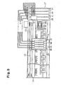
- Fig. 3 shows the fundamental structure of an ink jet type recording apparatus that employs the ink supply system shown in Fig. 1 .
- the carriage is indicated by reference numeral 11.
- This carriage is guided to a scan guide member 14 via a timing belt 13, which is driven by a carriage motor 12, and the carriage 11 is moved reciprocally in the lengthwise direction of a paper-feeding member 15, i.e., the main scan direction or the widthwise direction of recording paper.
- An ink jet type recording head 4 (see Fig. 4 ) is mounted on the side of the carriage 11 that faces the paper-feeding member 15, though not shown in Fig. 3 .
- valve units 3B, 3C, 3M, and 3Y for supplying inks to the recording head 4.
- each valve unit may be illustrated by simply using reference numeral 3.
- four valve units 3B, 3C, 3M, and 3Y are provided in association with the respective inks (e.g., black ink B and individual color inks of cyan C, magenta M, and yellow Y) to temporarily store the respective inks inside.
- each ink cartridge may be illustrated by simply using reference numeral 1.
- Capping means 18, which can seal the nozzle-forming surface of the recording head 4, is located in a non-print area (home position) on the moving passage of the carriage 11.
- a cap member 18a formed of an elastic material, such as rubber, which comes in close contact with the nozzle-forming surface of the recording head 4 to be able to seal the nozzle-forming surface.
- the capping means 18 moves (rises) toward the recording head 4, so that the nozzle-forming surface of the recording head 4 is sealed by the cap member 18a.
- the cap member 18a seals the nozzle-forming surface of the recording head 4 while the recording apparatus is at rest and prevents the nozzle opening from being dried.
- Connected to the bottom portion of the cap member 18a is one end of a tube of a suction pump (tube pump) for performing a cleaning operation. At the time of the cleaning operation, a negative pressure produced by the suction pump is caused to act on the recording head 4 to suck and discharge ink from the recording head 4.
- a wiping member 19 of an elastic material, such as rubber, formed into a rectangular slice, is arranged adjacent to the capping means 18 on the print area side of the capping means 18, and moves to the moving passage of the recording head 4, as needed, to wipe the nozzle-forming surface clean.
- Reference numeral 5 indicates an air-pressurizing pump, and with that attached to the cartridge holder 17, the air pressurized by the air-pressurizing pump 5 is led into the outer case 7 in each ink cartridge 1B, 1C, 1M, and 1Y. Then, the positive pressure of the pump 5 causes the ink from each ink cartridge 1B, 1C, 1M, and 1Y to be supplied to each of the valve units 3B, 3C, 3M, and 3Y on the carriage 11 via each tube 2.
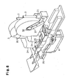
- Figs. 4 and 5 show the structures of the aforementioned valve unit 3 and the recording head 4 that receives the ink from the valve unit 3.
- Figs. 4 and 5 illustrate the state where two valve units 3 are mounted on the top portion of the recording head 4 for the sake of descriptive convenience, there may be a case where a plurality of valve units 3 are further mounted in association with the ink colors spurted from a single recording head 4. Further, a plurality of sets may be prepared, each having two valve units 3 with respect to a single recording head 4, as shown in Figs. 4 and 5 .
- the outline of the valve unit 3 is constituted by a unit case 20 of a synthetic resin formed in a flat shape, and a connection portion 21 is formed at one end.
- the tube 2 is connected to the connection portion 21.
- the ink supplied from each ink cartridge 1 is led into the valve unit 3 via the connection portion 21.
- a flexible film member 22 is adhered to one side of the valve unit 3 by thermal deposition and constitutes a part of a pressure chamber 34, to be discussed later.
- the film member 22 be soft so that it can efficiently sense the negative pressure state, does not chemically influence the ink properties, and is of a material with low water transmittance and low oxygen and nitrogen transmittance. It is therefore desirable that the film member 22 should be able to adhere and laminate a nylon film coated with vinylidene chloride (saran) on a high-density polyethylene film or polypropylene film.
- This pressure-receiving plate 23 should be light so that, when the carriage moves due to the printing operation or the like, the dead weight of the pressure-receiving plate 23 and the acceleration of the carriage do not move the film member 22 to otherwise change the pressure in the pressure chamber 34.
- the pressure-receiving plate 23 should desirably be formed of a plastic material, such as polyethylene or polypropylene.
- the pressure-receiving plate 23 may be attached to the film member 22 by thermal deposition before the film member is attached to the unit case 20, or the pressure-receiving plate 23 may be attached to the film member 22 by an adhesive or by a double-faced adhesive tape or the like after the film member 22 is attached to the unit case 20.
- this pressure-receiving plate 23 is formed like a disk in the embodiment illustrated in the drawings, it is not particularly limited to a disk shape. In a case where the pressure chamber 34 to be formed inside the valve unit 3 forms a thin cylindrical space as will be discussed later, however, it is desirable to use a disk-like pressure-receiving plate 23 and arrange the pressure-receiving plate 23 concentrically with respect to the pressure chamber 34.
- an ink lead-out portion 24 is formed in the valve unit 3 and a ring-like connection member 25 is intervened between the ink lead-out portion 24 and a head support 26 of the recording head 4. Then, the inks are supplied to the recording head 4 from the valve units 3 via the connection members 25, respectively.
- a groove-like ink lead-in passage 31 is formed in the unit case 20 that constitutes the outline of the valve unit 3 as shown in Fig. 7 .
- the ink that is supplied from the connection portion 21 via the tube 2 is supplied to an ink supply chamber 32, formed nearly in the center of the unit case 20, via the ink lead-in passage 31.
- This ink supply chamber 32 is constructed by a small-capacity cylindrical space as shown in Fig. 8 , and a spring seat 33 is fitted in the ink supply chamber 32 at the side of the unit case 20. Then, with the spring seat 33 fitted, a film member 37 is thermally deposited with respect to the unit case 20 in such a way as to cover the ink supply chamber 32 and the ink lead-in passage 31, thereby sealing the ink supply chamber 32 and the ink lead-in passage 31.
- a partition 35 is formed between the ink supply chamber 32 and the pressure chamber 34 in such a way as to define both, and a support hole 36 for slidably supporting a movable valve 38, which constitutes an open/close valve, is formed in this partition 35.
- the movable valve 38 comprises a plate-like member 38a and a rod member 38b, which is formed integrally in the center portion of the plate-like member 38a and slides in the support hole 36.
- a coil-shaped seal spring 39 as an urging member, is located between the plate-like member 38a and the spring seat 33, and the action of the seal spring 39 urges the plate-like member 38a, with slight pressing force, toward the partition 35, i.e., in the direction of closing an ink supply hole 42.
- a rubber seal member 41 formed like a ring is attached to the partition 35 by thermal deposition or the like in such a way as to surround the support hole 36. Therefore, the plate-like member 38a of the movable valve 38 abuts on the seal member 41 by the urging force of the seal spring 39.
- the seal member 41 may be an O-ring or the like, but elastomer resin or the like may be formed integral with the unit case 20 by dichroic formation to be used as the seal member.
- a plurality of cutaway holes 42a are intermittently formed around the support hole 36 of the partition 35, as shown in the enlargement in Fig. 9 , and those cutaway holes 42a constitute the ink supply hole 42 extending from the ink supply chamber 32 to the pressure chamber 34.
- cutaway holes 42a are formed around the support hole 36.
- the seal member 41 is provided on the partition 35 in such a way as to surround the outside of the ink supply hole 42.
- the pressure chamber 34 of the unit case 20 is constituted by a recess portion 44, which has a cylindrical shape cut away from the unit case 20.
- the film member 22 is tightly attached by thermal deposition means to that side of the unit case 20 where the recess portion 44 is formed. That is, the pressure chamber 34 is constructed by the recess portion 44 formed in the unit case 20 and the film member 22 covering it.
- An outlet 45 of the pressure chamber 34 is formed in the topmost portion in the gravitational direction as shown in Fig. 6 .
- An ink lead-out passage 46 which connects to the outlet 45 of the pressure chamber, is formed in an arc shape along the recess portion 44.
- the outlet 45 of the pressure chamber 34 and the ink lead-out passage 46 are constituted by groove portions formed in the unit case 20 in association with them and the film member 22, which covers those groove portions.
- the ink lead-out passage 46 penetrates through the unit case 20 in the proximity of the ink lead-out portion 24 and is connected to the ink lead-out portion 24.
- the ink is lead out vertically at the ink lead-out portion 24 and is supplied to the recording head 4, as mentioned earlier.
- the ink is supplied to the valve unit 3 by a positive pressure by using the ink supply system shown in Fig. 1 or Fig. 2 .
- the supply flow rate of the ink in this case has only to be set to a level that copes with the amount of ink the recording head 4 consumes in the printing operation.
- the aforementioned cleaning operation is executed, as the nozzle-forming surface of the recording head 4 is sucked by using the capping means 18, the flow rate of the ink to be supplied to the valve unit 3 increases.
- a spring load W1 (not shown) by the seal spring 39 in the valve unit 3 is applied to the plate-like member 38a of the movable valve 38 and pressure P1 (not shown) of the ink to be supplied to the ink supply chamber 32 is also applied to the plate-like member 38a. Accordingly, the plate-like member 38a abuts on the seal member 41 as shown in Fig. 8(a) , rendering the movable valve 38 in a valve-closed state. That is, the valve unit 3 is in a self-sealing state.
- the ink in the ink supply chamber 32 is supplied into the pressure chamber 34 via the ink supply hole 42, canceling the negative pressure in the pressure chamber 34. Accordingly, the movable valve 38 moves and is switched to the valve-closed state again as shown in Fig. 8(a) , stopping the supply of the ink to the pressure chamber 34 from the ink supply chamber 32.
- the movable valve 38 is not frequently switched between the states shown in Fig. 8(a) and Fig. 8(b) , and the film member 22 keeps the balanced state of abutting on the end portion of the rod member 38b of the movable valve 38 during the printing operation, while as the ink is consumed, it works on the pressure chamber 34 in such a way as to successively supplement the ink by opening the valve slightly.
- the pressure-receiving plate 23 can receive the displacement action of the film member 22 on its entire surface. Therefore, the displacement action of the film member 22 can be transmitted surely to the movable valve 38, so that the reliability of the operation of the movable valve 38 can be improved.
- the pressure chamber 34 because the outlet 45 of the pressure chamber 34 is formed at its topmost portion along the gravitational direction, the pressure chamber 34 can be filled with the ink without leaving air (bubbles) at the time of, for example, the initial filling to feed the ink to the recording apparatus.
- the ink supply system from the ink cartridge 1 to the recording head 4 is constituted by a closed passage into which the ink can be filled.
- Figs. 10(a) to 10(d) show a preferable fabrication process in the manufacturing method for the valve unit 3, particularly, in a case where the flexible film member 22, which constitutes part of the pressure chamber 34 of the valve unit 3, is thermally deposited to the unit case 20.
- the film member 22 is thermally deposited to the unit case 20 with the adequate flexibility.
- the film member 22 is thermally deposited to the unit case 20 in that state, the film member 22 is rendered in a state with the adequate flexibility in the usage at normal temperature.
- the unit case 20 is placed on a heater block 51 for heating with the recess portion 44 constituting the pressure chamber 34 being the top surface. Accordingly, the unit case 20 is heated by the heater block 51 and is thermally expanded in the direction of an arrow C shown in Fig. 10(a) , i.e, toward both outer sides. Subsequently, the film member 22 is placed in such a way as to cover the recess portion 44 of the heated unit case 20 as shown in Fig. 10(b) .
- a heater block 52 for thermal deposition is moved down from above the film member 22 to apply the proper pressure, thereby thermally depositing the film member 22 to the unit case 20.
- the unit case 20 is removed from the individual heater blocks 51 and 52 and is naturally cooled down to the normal temperature, so that the thermal expansion of the unit case 20 is absorbed and it contracts slightly. This can provide the unit case to which the film member 22 is thermally deposited with the adequate flexibility.
- Figs. 11(a) to 11(c) show another preferable fabrication process in case of thermally depositing the flexible film member 22 to the unit case 20.
- the film member 22 can be thermally deposited to the unit case 20 while the film member 22 is bent adequately by using the thickness of the pressure-receiving plate attached to the film member 22.
- the pressure-receiving plate 23 is attached to one side of the film member 22.
- the pressure-receiving plate 23 may be attached to the film member 22 by an adhesive or by a double-faced adhesive tape or the like, it is preferable to attach the film member 22 to the pressure-receiving plate 23 by thermal deposition.
- the film member 22 to which the pressure-receiving plate 23 is attached is placed with the pressure-receiving plate 23 being the top with respect to the unit case 20, which is placed with the recess portion 44 being the top surface.
- the heater block 52 for thermal deposition is moved down from above the film member 22, as shown in Fig. 11(c) , to apply the proper pressure, thereby thermally depositing the film member 22 to the unit case 20.
- the center portion of the film member 22 with the pressure-receiving plate 23 attached thereto is pressed into the recess portion 44 side in association with the thickness of the pressure-receiving plate 23 in the process of thermal deposition.
- the peripheral portion of the film member 22 is thermally deposited to the unit case 20 by the heater block 52. This can provide the unit case 20, to which the film member 22 is thermally deposited, with the adequate flexibility.
- the movable valve 38 shown in Fig. 8 and the seal spring 39 are inserted in the ink supply chamber 32 of the unit case 20 of the unit case 20 to which the film member 22 is thermally deposited, the spring seat 33 is fitted in the end face of the ink supply chamber 32, and the ink supply chamber 32 and the ink lead-in passage 31 are sealed by the film member 37, thus yielding the valve unit 3.
- Fig. 12 shows another preferable mode of the valve unit 3. Note that the basic structure of the valve unit 3 shown in Fig. 12 is also shown in Fig. 8 that has already been discussed, and its main essential portions are indicated by the same numerals.
- the outer surface of the film member 22 thermally deposited to the unit case 20 is further covered with a non-water-transmittive film member 54.
- a soft material is used for the film member 22 that constitutes a part of the pressure chamber 34 so that the negative pressure state can be sensed efficiently, and the soft material does not chemically influence the ink property. Therefore, high-density polyethylene or polypropylene can be suitably used for the film member 22, as mentioned earlier. Because the material has a slight water transmittance, however, there is a technical problem such that moisture evaporated from the ink in the pressure chamber 34 is scattered outside from the pressure chamber 34.
- the degree of scattering of moisture evaporated from the ink in the pressure chamber 34 outside the pressure chamber 34 is reduced by further coating the outer surface of the film member 22 with the non-water-transmittive film member 54 as shown in Fig. 12 .
- An aluminum foil or high polymer film with aluminum vapor deposited thereon can be used as the non-water-transmittive film member 54.
- valve unit 3 shown in Figs. 13(a) and 13(b) can be employed suitably. It is to be noted that the basic structure of the valve unit 3 shown in Figs. 13(a) and 13(b) is illustrated in Figs. 6 to 8 that have already been discussed, and its main essential portions are indicated by the same numerals.
- the mode shown in Figs. 6 to 8 is provided with a lid 56, which seals the outer surface of the film member 22.
- a through hole 57 is formed in a part of the lid 56, and a single zigzagging groove portion 58, which communicates with this through hole 57, is formed on the surface of the lid 56.
- the end portion of the groove portion 58 is connected to a bottomed hole 59 formed in the lid 56.
- the through hole 57, the groove portion 58, and the hole 59 are covered with a single film member 60.
- the film member 60 is preferably adhered to the lid 56 by thermal deposition means. Then, an air release port is formed by breaking the film member 60 covering the hole 59 with a sharp tool or the like.
- the film member 22, which constitutes a part of the pressure chamber 34 in the valve unit 3, is covered with the lid 56 in an airtight state and is connected to the air release port (indicated by the same reference numeral 59 as that of the bottomed hole) via the air flow passage (indicated by the same reference numeral 58 as that of the groove portion) that is formed by covering the through hole 57 and groove portion 58, formed in the lid 56, with the film member 60.
- the pressure inside the lid 56 is kept constant, and no problem would arise. Scattering of moisture via the film member 22, which constitutes a part of the pressure chamber 34, goes through the long air flow passage 58, and is thus suppressed effectively.
- the connection portion 21 for connecting the tube 2 is formed on the top portion of its unit case 20, and the ink lead-out portion 24 is formed at the bottom portion of the unit case 20.
- Formed on the first side surface of the unit case 20 are a filter-chamber recess portion 61, a center recess portion 62, a first groove portion 63 that communicates with the center recess portion 62, and a second groove portion 64 located apart from them.
- the film member 37 is thermally deposited to the first side surface of the unit case 20 in such a way as to cover the filter-chamber recess portion 61, the center recess portion 62, and the first and second groove portions 63, 64. Therefore, the filter-chamber recess portion 61 becomes a filter-retaining chamber 66, the first groove portion 63 becomes an ink lead-in passage 31, and the second groove portion 64 becomes an ink lead-out portion 46.
- a through hole h1 formed at the lower portion of the filter-chamber recess portion 61 are a through hole h1, and an inclined portion 61a with an inclined surface whose depth from the first side surface increases toward the through hole h1.
- a filter member 67 is secured to the lower portion of the filter-chamber recess portion 61 along the gravitational direction by thermal deposition in such a way as to cover the inclined portion 61a. Therefore, a bubble remaining portion 66a where bubbles remain is formed above the filter member 67 in the filter-retaining chamber 66.
- the filter member 67 is formed of twill-woven stainless steel or unwoven fabrics or the like.
- a recess portion 69 that forms the pressure chamber 34 and a third groove portion 70 that communicates with filter-chamber recess portion 61 and the first groove portion 63 are formed in the second side surface of the unit case 20 opposite to the first side surface.
- a film member 72 is thermally deposited to the second side surface, which allows the recess portion 69 to be the pressure chamber 34, and allows the third groove portion 70 to be a part of the ink lead-in passage 31.
- the film member 72 is made of alumina (Al 2 O 3 ) vapor-deposited PET (polyethylene-terephthalate) bonded to high-density polyethylene or polypropylene.
- the alumina vapor-deposited on the PET is equivalent to a gas barrier layer.
- PET is the material that remains relatively unchanged in size and rigidity with respect to an environmental change, such as a humidity change, and demonstrates a similar flexibility with respect to the same pressure.
- the film member 72 in use has a 20- ⁇ m thick film S1 of high-density polyethylene or polypropylene, an alumina vapor-deposited layer S2 of 500 angstroms, and a 12 ⁇ m thick PET film S3.
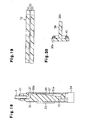
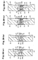
- the seal member 41 provided on the unit case 20 in the first embodiment is formed integral with the movable valve 38 in the second embodiment, as shown in Fig. 20 .
- a pressure-receiving plate is formed of a plastic material, such as polyethylene or polypropylene, as per the first embodiment, and its thickness is, for example, about 0.8 mm.
- FIG. 21(a) and 21(b) A manufacturing method for the valve unit 3 of the second embodiment will be described next referring to Figs. 21(a) and 21(b) and Figs. 22(a) and 22(b) .
- a description will be given of a manufacturing method that thermally deposits the flexible film member 72, which constitutes a part of the valve unit 3, to the unit case 20.
- the film member 72 to which the pressure-receiving plate 23 is bonded is placed on the unit case 20, and the heater block 52 is moved down with respect to the film member 72.
- the heater block 52 in the present embodiment is provided with a projection 52a of a heat insulating material at its center. That is, when the heater block 52 is lowered, and the adequate pressure is applied to the film member 72, the projection 52a presses the pressure-receiving plate as shown in Fig. 21(b) . In this state, the heater block 52 presses the film member 72 against the unit case 20, thermally depositing the film member 72 to the unit case 20. Removing the heater block 52 from the unit case 20 yields a unit case 20 to which is thermally deposited a film member 72 having a sufficient flexibility.
- the heater block 52 having a chuck hole 52b formed in the center can be used as shown in Fig. 22(b) .
- the film member 72, to which the pressure-receiving plate 23 is adhered is placed on the unit case 20 as shown in Fig. 22(a) .
- the heater block 52 is moved down, and air between the heater block 52 and the unit case 20 is discharged through the chuck hole 52b. Accordingly, the pressure-receiving plate 23 is chucked to the chuck hole 52b. In this state, the heater block 52 presses the film member 72 against the unit case 20 to thermally deposit it to the unit case 20. As the heater block 52 is removed, the unit case 20 to which the film member 72 having a sufficient flexibility is thermally deposited is yielded.
- the second embodiment affords the same effects as the first embodiment, and can provide the following effects.
- the filter-retaining chamber 66 is provided midway between the ink lead-out portion 24 and the ink supply chamber 32, and the filter member 67 is provided in the filter-retaining chamber 66.
- the filter member 67 can catch foreign matters, such as dust, it is possible to reduce poor sealing of the seal member 41 caused by mixture of foreign matters.
- the filter member 67 As the filter member 67 is located at the lower portion of the filter-retaining chamber 66, and space is formed above the filter member 67, bubbles bu remain in the bubble remaining portion 66a above the filter member 67 by buoyancy, as indicated by a two-dash chain line in Fig. 17 . Therefore, it is hard for the bubbles in the filter-retaining chamber 66 to enter the through hole h1, thus the ink can be supplied to the ink supply chamber 32 and the pressure chamber 34 more surely, and the movement of the movable valve 38 can be made more reliably.
- the through hole h1 leading to the ink supply chamber 32 is connected to the lower portion of the filter-retaining chamber 66, where the filter member 67 is provided.
- the bubbles bu receive a large resistance in passing the filter member 67, so that if the bubbles bu remain in the filter-retaining chamber 66, it is hard for them to move downward even if certain shocks are applied to them. It is therefore more difficult for the bubbles bu remaining in the filter-retaining chamber 66 to enter the ink supply chamber 32 via the through hole h1 positioned in the lower portion of the filter-retaining chamber 66. This makes it possible to supply the ink to the ink supply chamber 32 and the pressure chamber 34 more surely, and to prevent the bubbles bu from flowing out to the recording head 4 during printing.
- the film member 72 in the second embodiment has the alumina-vapor-deposited layer sandwiched between synthetic resin films (the high-density polyethylene or polypropylene film, and the PET film).
- synthetic resin films the high-density polyethylene or polypropylene film, and the PET film.
- the film member 27 is formed of a soft synthetic resin, and easily deforms by a small negative pressure produced by discharging of a liquid, therefore, the open/close valve can be opened reliably. Since the alumina vapor-deposited layer S2 is provided between the synthetic resin films, the film member 72 can be formed of a material of a low gas transmittance, and the properties of liquid, such as viscosity, in the pressure chamber 34 have less moisture-evaporation originated changes.
- the alumina vapor-deposited layer S2 is formed of aluminum oxide, the material is likely to influence the ink in the pressure chamber 34, but it is sandwiched between the synthetic resin films, and thus it does not cause a chemical change on the property of liquid. The operational reliability of the valve unit 3 can therefore be improved.
- the film member 72 of the second embodiment is an alumina-vapor-deposited PET film bonded to a high-density polyethylene or polypropylene film.
- the use of the film member 72 of such a material can make changes in size and rigidity small with respect to an environmental change, such as a humidity change, and can always provide a similar flexibility with respect to the same pressure.
- As the film member 72 has a low gas transmittance and moisture transmittance it is possible to suppress evaporation of moisture, mixture of gas, and the like via the film member 72. It is therefore possible to suppress a change in the viscosity of the ink in the pressure chamber 34 defined by the film member 72 and the generation of bubbles.
- the seal member 41 is formed integral with the movable valve 38.
- the seal member 41 is formed integral with the movable valve 38 without being deposited on the unit case 20.
- the seal member 41 is formed integral with the movable valve 38 as in this embodiment, however, good sealing can be guaranteed if the unit case 20 is formed of a material quite different from that of the seal member 41. This can widen the range of selection of the materials for the unit case 20 and the film members 72, 37 to be deposited thereto, thus enabling selection of materials of lower costs.
- the pressure-receiving plate 23 of the second embodiment is formed of a plastic material, such as polyethylene or polypropylene, with a thickness of 0.8 mm or more. A sufficient rigidity can be obtained even if the pressure-receiving plate 23 is formed of a flexible material, which is approximately the same as that of the film members 72, 37 to easily thermally deposit the pressure-receiving plate 23 to the film members 72, 37. Accordingly, the pressure-receiving plate 23 does not deform itself, and receives a change in pressure in the pressure chamber 34 so that the movable valve 38 can be operated more reliably.
- a plastic material such as polyethylene or polypropylene
- the heater block 52 which is used to thermally deposit the film member 72 to the unit case 20 has the projection 52a in its center. With the projection 52a pressing the pressure-receiving plate 23, therefore, the film member 72 is deposited to the unit case 20. That is, it is possible to acquire the valve unit 3 that has the film member 72 deposited to the unit case 20 with some flexibility.
- the flexibility can thus suppress the reaction force at the time a negative pressure is generated in the pressure chamber 34, and the film member 72 presses the movable valve 38. Even if an environmental change occurs, the film member 72 does not get strained, and the operational pressure of the film member 72 can be kept uniform by suppressing the reaction force of the film member 72 as much as possible.
- the projection 52a of the heater block 52 that presses the pressure-receiving plate 23 is formed of a heat insulating material. It is therefore hard for the heat to be transmitted to the film member 72 via the pressure-receiving plate 23, so that only the necessary portion can be thermally deposited easily.
- the chuck hole 52b is provided in the center of the heater block 52 in the second embodiment. Therefore, the air is evacuated from the chuck hole 52b, causing the pressure-receiving plate 23 to be chucked to the chuck hole 52b.
- the film member 72 As the film member 72 is deposited to the unit case 20 in this situation, the film member 72 given with a sufficient flexibility can be deposited to the unit case 20 by a simple structure. Therefore, it is possible to suppress, as much as possible, the reaction force at the time a negative pressure is generated in the pressure chamber 34, and the film member 72 presses the movable valve 38, and possible to keep the operational pressure of the film member 72 uniform.
- the first and second embodiments may be modified as follows.
- the size and shape of the filter member 67 provided in the filter-retaining chamber 66 may be changed.
- the pressure-receiving plate 23 may be provided inside the film member 72 (on the unit case 20 side) instead of being provided on the outside.
- a plurality of projections 52a may be provided on the heater block 52 and, with those projections 52a pressing the pressure-receiving plate 23 at plural locations, the film member 72 may be thermally deposited to the unit case 20.
- the unit case 20 may be provided with an annular projection so that the film member 72 is thermally deposited to the unit case 20 by pressing the pressure-receiving plate 23 with this projection.
- recess portions 75 may be provided between the filter-chamber recess portion 61, the recess portion 62, and the groove portions 63, 64; outside the groove portion 64; and outside the recess portion 69 in order to reduce the weight.
- the carriage 11 becomes lighter accordingly, thus making it possible to reduce the load of the mechanism that activates the carriage, and to make the recording apparatus smaller.
- the projection 52a is formed of a heat insulating material in the second embodiment, the projection 52a may be integrally formed of the same material as the portions other than the projection 52a.
- the film member 72 in the second embodiment may be high-density polyethylene or polypropylene, to which PET vapor-deposited with silica (SiOx) is bonded.
- high-density polyethylene or polypropylene, to which PS (polystyrene) vapor-deposited with silica or with alumina is bonded, may be used.
- the embodiments may be a liquid injecting apparatus that injects another liquid.
- it may be a liquid injecting apparatus that injects liquid, such as an electrode material or coloring material, which is used in manufacturing a liquid crystal display, EL display, and surface emission display; a liquid injecting apparatus that injects a bioorganic substance, which is used in fabricating bio chips; or a sample injecting apparatus, such as a precision pipet.
- a plurality of restriction projections 76 may be formed on the bottom of the recess portion 44, facing the pressure-receiving plate 23, in order to restrict the displacement of the film member 22 when the pressure in the pressure chamber 34 is significantly reduced, for example, at the time of the cleaning operation.
- the projection 76 in this modification comprises four arcuate projections, which protrude from the bottom of the recess portion 44 in such a way as to surround the rod member 38b.
- An ink passage is formed between the adjoining restriction projections 76.
- Those restriction projections 76 are arranged on the circumference concentric to the axial line of the rod member 38b.
- the interval, H, between each restriction projection 76 and the film member 22 is set smaller than a clearance G, which is formed between the plate-like member 38a and the spring seat 33 when the plate-like member 38a of the movable valve 38 in the valve-closed state abuts on the seal member 41.
- each restriction projection 76 is formed smaller than the clearance G in this modification, a clearance is secured between the plate-like member 38a of the movable valve 38 and the spring seat 33 even when the displacement of the film member 22 is restricted, so that the seal spring 39 will not compressed more than needed.
- the structures of the pressure-receiving plate and each restriction projection differ from those of the modification in Figs. 26(a) and 26(b) . That is, in the further modification, the pressure-receiving plate 23 is attached to the inner surface of the film member 22, and the individual restriction projections 76 protrude from the pressure-receiving plate 23 toward the bottom of the recess portion 44.
- the clearance, I, between each restriction projection 76 and the bottom of the recess portion 44 is set smaller than the clearance G, which is formed between the plate-like member 38a and the spring seat 33 when the plate-like member 38a of the movable valve 38 in the valve-closed state abuts on the seal member 41.
- a negative-pressure holding spring 40 is arranged in the pressure chamber 34 in such a way as to encircle the rod member 38b of the movable valve 38.
- This negative-pressure holding spring 40 has one end held by a ring-shaped projection formed on the partition 35 and the other end abutting on the film member 22.
- the urging direction of the negative-pressure holding spring 40 therefore matches with the moving direction of the pressure-receiving plate 23, which is attached to the film member 22, and the urging force acts in the direction of expanding the volume of the pressure chamber 34.
- the coil diameter of the negative-pressure holding spring 40 is about the same as the coil diameter of the aforementioned seal spring 39 and is relatively small. Therefore, the negative-pressure holding spring 40 abuts on nearly the center of the pressure-receiving plate 23 via the film member 22.
- the ink is supplied to by a positive pressure as per the individual embodiments described above.
- the flow rate of the ink to be supplied to the valve unit 3 is increased to suck the nozzle-forming surface of the recording head 4 by using the capping means 18.
- the spring load W1 (not shown) by the seal spring 39 in the valve unit 3 is applied to the plate-like member 38a of the movable valve 38 and pressure P1 (not shown) of the ink to be supplied to the ink supply chamber 32 is also applied to the plate-like member 38a. Accordingly, the plate-like member 38a abuts on the seal member 41 as shown in Fig. 29(a) , rendering the movable valve 38 in a valve-closed state. That is, the valve unit 3 is in a self-sealing state.
- the film member 22 is displaced toward the recess portion 44, in accordance with a decrease in the ink in the pressure chamber 34, so that the pressure-receiving plate 23 attached to it moves in the direction of reducing the volume of the pressure chamber 34.
- the negative-pressure holding spring 40 is compressed, and the center portion of the pressure-receiving plate 23 abuts on the end portion of the rod member 38b of the movable valve 38 via the film member 22.
- W2 (not shown) represents the spring load of the negative-pressure holding spring 40 at that time
- Wd (not shown) represents displacement reaction force with respect to the displacement of the film member 22.
- P2 As the ink is further consumed by the recording head 4, a negative pressure P2 is generated in the pressure chamber 34.
- P2 > W1+P1+Wd+W2 the film member 22 pushes the rod member 38b, releasing the abutment of the plate-like member 38a to the seal member 41 so that the movable valve 38 becomes a valve-open state as shown in Fig. 29(b) .
- the ink in the ink supply chamber 32 is supplemented into the pressure chamber 34 via the ink supply hole 42 extending from the ink supply chamber 32 to the pressure chamber 34, and the flow of the ink into the pressure chamber 34 cancels the negative pressure in the pressure chamber 34. Accordingly, the movable valve 38 moves and is rendered in the valve-closed state again as shown in Fig. 29(a) , stopping the supplement of the ink to the pressure chamber 34 from the ink supply chamber 32.
- the negative-pressure holding spring 40 abuts on the film member 22, presses the pressure-receiving plate, and urges in the direction of increasing the volume of the pressure chamber 34. Even if the pressure-receiving plate 23 experiences slight acceleration/deceleration by the reciprocal movement of the carriage, for example, the pressure-receiving plate 23 does not recklessly move. This can effectively reduce the possible occurrence of the erroneous operation of the movable valve 38.
- the negative-pressure holding spring 40 also effectively suppresses the phenomenon such that the ink gathers in the lower portion of the pressure chamber 34 due to its gravitational force and expands the film member 22 further outward. That is, as the negative-pressure holding spring 40 has an action to always keep the pressure chamber 34 in a slight negative pressure state, it works so as to always keep the pressure-receiving plate 23, attached to the film member 22, in a vertical state. This can effectively reduce the erroneous operation of the movable valve 38.
- the negative-pressure holding spring 40 expands and works to keep the pressure chamber 34 in a slight negative pressure state, a variation in pressure in the pressure chamber 34 can be reduced. This can guarantee the proper discharge operation of ink droplets from the recording head.
- the spring load originated from the negative-pressure holding spring 40 and the seal spring 39 is applied to the movable valve, the negative pressure state of the pressure chamber 34 is secured.
- the spring load can be divided to the negative-pressure holding spring 40 and the seal spring 39. It is therefore possible to select a small spring load for the seal spring 39 for abutting the movable valve 38 in the valve-closed state on the seal member 41.
- the abutment pressure on the seal member 41 of an elastomer resin or the like can be lowered, thereby making it possible to prevent abnormal deformation of the seal member 41. Because application of an excess spring load onto the seal member 41 can be suppressed, it is possible to avoid the problem such that an impurity, such as oil and fat, contained in the elastomer resin constituting the seal member 41 enters the ink.
- the size relationship should be set in such a way as to leave a stroke where the negative-pressure holding spring 40 is further contractible in a case where the movable valve 38 moves the maximum, based on the contraction of the volume of the pressure chamber.
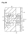
- Fig. 30 shows that example, and shows, in enlargement, near the center portion of the ink-supply valve unit.
- Fig. 30 shows a situation where the negative-pressure holding spring 40 is deformed or is contracted the most, based on the contraction of the volume of the pressure chamber 34.
- L1 indicates the solid height of the seal spring 39 in a case where the movable valve 38 makes the maximum movement
- L2 indicates the contracted height of the negative-pressure holding spring 40 in that state. That is, the size relationship among the individual portions is set in such a way that even when the individual turn portions of the seal spring 39 are tight, the individual turn portions of the negative-pressure holding spring 40 keep a not-tight state. In other words, in a case where spring members with the same standard (size) are used as the seal spring 39 and the negative-pressure holding spring 40, the sizes of the individual portions are set in such a way that the relationship of L1 ⁇ L2 is satisfied.
- the slight open state of the movable valve 38 can lead the ink into the pressure chamber 34 so that the size setting as shown in Fig. 30 is not essential.
- the ink supply pressure is low so that the large open state of the movable valve 38 continues to be needed. It is therefore important to set the solid height of the negative-pressure holding spring 40 with some margin with respect to the moving stroke of the movable valve 38 as mentioned above.
- the spring 40 works to always keep the pressure-receiving plate 23 in a vertical state.
- the pressure-receiving plate 23 in a vertical state even if the ink gathers in the lower portion of the pressure chamber 34 due to the gravitational force and causes the film member 22 to expand further outward. It is therefore possible to effectively reduce the erroneous operation of the movable valve 38.
- a coil spring is likewise used as the negative-pressure holding spring
- a plurality of coil springs 40a and 40b with smaller coil diameters are used in this mode.
- the individual coil springs 40a and 40b are arranged in such a way as to abut on near the periphery of the pressure-receiving plate 23 formed in a disk shape.
- the individual coil springs 40a and 40b work to always keep the pressure-receiving plate 23 in a vertical state, even if the ink gathers in the lower portion of the pressure chamber 34 due to the gravitational force and causes the film member 22 to expand further outward. It is therefore possible to effectively reduce the erroneous operation of the movable valve 38.
- a plate spring 40A is used as the negative-pressure holding spring.
- the plate spring 40A has both end portions bent in the same direction to constitute a pair of leg portions 40d and 40e. And, a cut and fold portion 40f which protrudes in the opposite direction to the bending direction of the leg portions 40d and 40e is formed in the center portion of the plate spring 40A.
- one leg portion 40d of the plate spring 40A is fixed to the unit case 20 in the pressure chamber 34 while the other leg portion 40e abuts on the inner wall of the pressure chamber 34.
- the rod member 38b of the movable valve is inserted in the opening that is bored through by forming the cut and fold portion 40f.
- the distal end portion of the cut and fold portion 40f is arranged in such a way as to abut on almost the center portion of the pressure-receiving plate 23 via the film member 22.
- the plate spring 40A urges the film member 22 in the direction of increasing the volume of the pressure chamber 34, and works to effectively suppress the erroneous operation of the movable valve 38 even if acceleration/deceleration originated from the reciprocal movement of the carriage, for example, is experienced.
- an ink jet type printer (hereinafter called printer) 121 as a liquid injecting apparatus has a frame 122 with a substantially parallelepiped shape and a paper-feeding member 123 hung from the frame 122, so that paper is fed on the paper-feeding member 123 by an unillustrated paper-feeding mechanism. Further, a guide member 124 is hung from the frame 122 in parallel to the paper-feeding member 123, and a carriage 125 is supported on the guide member 124 in such a manner as to be movable along the axial direction of the guide member 124. The carriage 125 is connected via a timing belt 127 to a carriage motor 128, and is moved reciprocally along the guide member 124 by driving of the carriage motor 128.
- printer ink jet type printer
- a liquid injecting head or recording head 129 is mounted on that side of the carriage 125, which faces the paper-feeding member 123.
- valve units 131 which supply liquids or inks to the recording head 129.
- four valve units 131B, 131C, 131M, and 131Y are provided in association with the colors of the inks (black ink B and individual color inks of cyan C, magenta M, and yellow Y).
- an unillustrated nozzle discharge port Provided in the bottom of the recording head 129 is an unillustrated nozzle discharge port, and the inks are supplied to the recording head 129 from the valve units 131B, 113C, 131M, and 131Y by the driving of an unillustrated piezoelectric element, and ink droplets are spurted onto the paper to perform printing.
- Each cartridge holders 132 are formed at the right-hand end of the frame 122.
- An ink cartridge 133 as liquid storing means is detachably mounted on each cartridge holder 132.
- four ink cartridges 133B, 133C, 133M, and 133Y are provided in association with the colors of the inks.
- Each of the ink cartridges 133B, 133C, 133M, and 133Y comprises an outer case 134, having the interior in an airtight state, and an unillustrated ink pack provided therein, and the aforementioned black ink B and the individual color inks C, M, and Y are respectively stored in the ink packs.
- the ink pack of the ink cartridge 133 and the valve unit 131 are connected together via a tube 138 as a flexible liquid supply passage.
- a tube 138 as a flexible liquid supply passage.
- four tubes 138B, 138C, 138M, and 138Y are provided in association with the colors of the inks.
- An air-pressurizing pump 139 is provided on the ink cartridge 133Y which stores the ink of yellow Y.
- This air-pressurizing pump 139 is connected to the outer cases 134 of the ink cartridges 133B, 133C, 133M, and 133Y via air-supply tubes 136B, 136C, 136M, and 136Y. Therefore, the air pressurized by the air-pressurizing pump 139 is introduced into the outer cases 134 of the ink cartridges 133B, 133C, 133M, and 133Y, and is led into the spaces formed between the outer cases 134 and the ink packs.
- the air-pressurizing pump 139 As the air-pressurizing pump 139 is driven, letting air go into the outer cases 134, the ink packs are pressed by pressurized air, and the individual inks stored in the ink packs are supplied to the valve units 131B, 131C, 131M, and 131Y via the tubes 138B, 138C, 138M, and 138Y.
- Capping means 141 which seals the nozzle-forming surface of the recording head 129, is arranged in a non-print area (home position) on the moving passage of the carriage 125. Further, a cap member 141a formed of an elastic material, such as rubber, which can come in close contact with the nozzle-forming surface of the recording head to seal the nozzle-forming surface is arranged on the top surface of the capping means 141.
- the capping means 141 moves up toward the recording head 129 and seals the nozzle-forming surface of the recording head 129 with the cap member 141a, thereby preventing the openings of the nozzles from being dried.
- An unillustrated suction pump (tube pump) is provided at the lower portion of the cap member 141a.
- This suction pump is connected to the lower portion of the cap member 141a via a suction tube.
- a suction pump is driven, air is sucked from the cap member 141a covering the recording head 129, which sucks the ink from the recording head 129 and discharges it.
- a wiping member 142 is arranged adjacent to the printing area side of the capping means 141.
- This wiping member 142 is formed of an elastic material, such as rubber, into a rectangular slice. The wiping member 142 moves onto the moving passage of the recording head 129, as needed, to wipe the nozzle-forming surface clean.
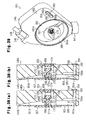
- valve unit 131 will be discussed according to Fig. 34 to Figs. 38(a) and 38(b) .
- the valve unit 131 has a unit case 145 of a synthetic resin.
- the unit case 145 has such a shape as the integral of a parallelepiped and semicolumnar portion.
- a connection portion 146 is formed at the top portion of the unit case 145, and the tube 138 is connected to the connection portion 146.
- An ink lead-out portion 147 is formed integrally at the lower portion of the unit case 145, and is connected to the recording head 129 via a connection member 125a of the carriage 125.
- a filter-chamber recess portion 149 where a filter 148 is retained, a substantially cylindrical small recess portion 150, a linear groove 151, which communicates with the small recess portion 150, and linear groove 152 extending horizontally.
- a film member 153 which covers the filter-chamber recess portion 149, small recess portion 150, and groove 151; and a film member 154, which covers the groove 152, are adhered to the first side surface 145a by thermal deposition.
- the filter-chamber recess portion 149 and the film member 153 constitute a filter chamber 155
- the small recess portion 150 and the film member 153 constitute a supply chamber 156
- the groove 151 and the film member 153 constitute a first ink lead-in passage 157.
- the groove 152 and the film member 154 constitute a flow-out passage 158, which communicates with the ink lead-out portion 147.
- the film members 153 and 154 are formed of materials that do not chemically influence the ink property and that further have low water transmittance and low oxygen and nitrogen transmittance. That is, the film members 153 and 154 are formed by a film with the structure in which, for example, a nylon film coated with vinylidene chloride (saran) is adhered and laminated on a high-density polyethylene film or polypropylene film.
- a nylon film coated with vinylidene chloride (saran) is adhered and laminated on a high-density polyethylene film or polypropylene film.
- a spring receiving member 159 which has an outside diameter slightly smaller than the inside diameter of the supply chamber 156, is attached to the film member 153 in such a way as to be positioned concentrically to the supply chamber 156 and there inside.
- a substantially cylindrical large recess portion 161 which is provided concentric to the small recess portion 150, and a linear groove 162 are formed on a second side surface 145b of the unit case 145.
- a peripheral wall portion 161a of the large recess portion 161 is inclined in such a way as to become wide toward the opening.
- the bottom wall of the large recess portion 161 has an inclined surface 161b, which is inclined in such a way that the depth of the large recess portion 161 gradually becomes smaller toward above.
- a through hole 152a which communicates with the groove 152 of the first side surface 145a, is formed in the lowermost portion of the large recess portion 161.
- the second ink lead-in passage 166 communicates with the filter chamber 155 via the through hole 162a and communicates with the first ink lead-in passage 157 via the through hole 162b. That is, the ink supplied from the tube 138 is supplied to the supply chamber 156 via the filter-chamber recess portion 149, the through hole 162a, the second ink lead-in passage 166, the through hole 162b, and the first ink lead-in passage 157.
- the connection portion for the large recess portion 161, which forms the pressure chamber 165, and the through hole 152a becomes a liquid outlet E.
- the film members 163 and 164 are constituted of the same material as the film members 153 and 154.
- a substantially disk-shaped pressure-receiving plate 167 is attached to that side of the film member 163 that is opposite to the pressure chamber 165.
- the pressure-receiving plate 167 has an outside diameter smaller than the inside diameter of the pressure chamber 165, and is arranged concentrically to the pressure chamber 165.
- the pressure-receiving plate 167 is formed of a material that is harder than the film member 163, e.g., a light plastic material, such as polyethylene or polypropylene.
- the pressure-receiving plate 167 is attached to the film member 163 by thermal deposition or by using an adhesive, a double-faced adhesive tape, or the like.
- a spring 170 which urges the film member 163, is provided in the pressure chamber 165 in such a way as to press the film member 163 and the pressure-receiving plate 167 outward.
- a support hole 169 is formed in a partition 168, which partition defines the aforementioned supply chamber 156 and pressure chamber 165 of the unit case 145.
- the support hole 169 communicates with the supply chamber 156 and the pressure chamber 165.
- a movable valve 171 is slidably supported in the support hole 169.
- the movable valve 171 has a columnar rod portion 171a inserted into the support hole 169 and a substantially disk-shaped plate-like member 171b, which is larger than the outer shape of the support hole 169.
- the rod portion 171a and the plate-like member 171b are formed integrally.
- the rod portion 171a is inserted in the support hole 169 and the spring 170 so that its distal end can be abutted on the film member 163.
- the plate-like member 171b is laid in the supply chamber 156.
- a circular seal member 172 such as an O-ring, is secured to the support hole 169 side of the plate-like member 171b in such a way as to surround the support hole 169.
- the movable valve 171 connects the supply chamber 156 to the pressure chamber 165, and when the seal member 172 abuts on the partition 168, it covers around the support hole 169, and disconnects the supply chamber 156 and the pressure chamber 165 from each other. Further, a step portion is formed on the film member 153 side of the movable valve 171. A coil-like spring 174 is fitted, at its one end, on this step portion and the other end of the spring 174 is engaged with the aforementioned spring receiving member 159. Accordingly, the spring 174 urges the movable valve 171 toward the pressure chamber 165.
- the support hole 169 has four cutaway grooves arranged at equal intervals, and is formed into a substantially cross shape as a whole. With the rod portion 171a of the movable valve 171 inserted into the support hole 169, therefore, four ink passages 173 are formed by the rod portion 171a and the support hole 169.
- the ink cartridges 133B, 133C, 133M, and 133Y of the individual colors are retained in the cartridge holders 132. Then, pressurized air is supplied to the outer cases 134 of the individual ink cartridges 133B, 133C, 133M, and 133Y via the air-supply tubes 136B, 136C, 136M, and 136Y from the pressurizing pump 139, pressing the ink packs. Accordingly, the individual inks in the ink packs are pressurized. Then, with the recording head 129 covered with the cap member 141a, the unillustrated suction pump is driven.
- the inks are supplied to the valve units 131B, 131C, 131M, and 131Y via the tubes 138B, 138C, 138M, and 138Y.
- the air in the filter chamber 155, the second ink lead-in passage 166, the first ink lead-in passage 157, the supply chamber 156 and pressure chamber 165, and the flow-out passage 158 is discharged from the recording head 129.
- the large recess portion 161 of the pressure chamber 165 has the inclined surface 161b at its top portion, the upper space of the pressure chamber 165 has become smaller, and the film deforms in a shape along the shape of the pressure chamber to be able to easily increase the negative pressure in the pressure chamber 165, thus making it easier for the air to be discharged.
- the suction pump is stopped.
- the movable valve 171 is urged by the spring 174, it moves toward the pressure chamber 165 and presses the seal member 172 against the partition 168, blocking the ink passages 173. Therefore, the movable valve 171 becomes the valve-closed state as shown in Fig. 38(a) . That is, the supply chamber 156 and the pressure chamber 165 go into the non-communicating state, and the valve units 131 go into the self-sealing state.
- the printer 121 performs test printing for the performance test. That is, the printer 121 prints by moving the carriage 125 rightward and leftward in Fig. 33 while adequately injecting the inks from the recording head 129 of the carriage 125, based on unillustrated test data.
- the film member 163 is bent against the spring 170, and the center of the film member 163 and the pressure-receiving plate 167 are displaced toward the supply chamber 156.
- the bent film member 163 presses the rod portion 171a of the movable valve 171 against the spring 174, pressing the movable valve 171 toward the supply chamber 156.
- the movable valve 171 is put in the state of the valve-open state as shown in Fig. 38(b) .
- the supply chamber 156 communicates with the pressure chamber 165 via the ink passage 173, and the ink in the supply chamber 156 flows into the pressure chamber 165, nullifying the negative pressure in the pressure chamber 165. Accordingly, the movable valve 171 moves toward the pressure chamber 165 by the urging force of the spring 174, and goes into the valve-closed state again as shown in Fig. 38(a) , thus stopping supplying the ink from the supply chamber 156 to the pressure chamber 165.
- the movable valve 171 is not frequently switched between the valve-open state and the valve-closed state, and the film member 163 is kept in the balanced state where it abuts on the end portion of the rod portion 171a of the movable valve 171. It works in such a way as to successively supply the ink to the pressure chamber 165 while opening the movable valve 171 slightly in accordance with the consumption of the ink.
- a variation in the pressure of the ink in the pressure chamber 165 is restricted within a predetermined range by opening/closing the movable valve 171, and is dissociated from a change in the pressure of the ink in the supply chamber 156. Even if a pressure change has occurred in the tube 138B, 138C, 138M, 138Y by the reciprocal movement of the carriage 125, therefore, its influence is not applied. As a result, the supply of the ink to the recording head 129 from the pressure chamber 165 is carried out well.
- the air may expand, possibly increasing the pressure in the pressure chamber 165. Because the spring 170 pushes the film member 163 open outward to absorb a change in the volume of the air in this embodiment, the pressure in the air chamber 165 does not go up.
- the ink pack is detached from each ink cartridge 133B, 133C, 133M, and 133Y. Then, the carriage 125 moves on the top surface of the capping means 141, and the unillustrated suction pump is driven with the recording head covered with the cap member 141a. This discharges the ink through the recording head 129 from the filter chamber 155, the second ink lead-in passage 166, the first ink lead-in passage 157, the supply chamber 156, the pressure chamber 165, and the flow-out passage 158. As the liquid outlet E is formed in the lowermost portion of the pressure chamber 165, the ink is discharged smoothly at this time.
- a cleaning liquid supply tube is connected to the cartridge holder 132 in place of each ink cartridge 133B, 133C, 133M, and 133Y. Then, a washing liquid is supplied to the tubes 138B, 138C, 138M, and 138Y, the valve units 131B, 131C, 131M, and 131Y, and the recording head 129 from the cleaning liquid supply tube and cleaning is performed.
- the printer 121 of the present embodiment can afford the following effects.
- the printer 121 of the present embodiment has a passage valve 175 disposed in the flow passage of the tube 138.
- This passage valve 175 is fixed to the frame 122 in the vicinity of the ink cartridge 133 so that the amount of the ink flowing in the tube 138 can be changed.
- the printer 121 of the present embodiment has a valve unit 181 shown in Figs. 39 and 40 , instead of the valve unit 131 of the fourth embodiment, mounted on the carriage 125.
- the passage valve 175 is disposed at the upstream side of the valve unit 181.
- the valve unit 181 has a conical surface portion 181b which makes the large recess portion 161 shallower toward the peripheral portion of the large recess portion 161 from the vicinity of the support hole 169, in place of the inclined surface 161b of the fourth embodiment.
- the liquid outlet E is formed in the position of 40% of the volume of the pressure chamber 165, not in the lowermost portion of the pressure chamber 165, and the through hole 152a is connected there.
- the liquid outlet E is formed in such a way that, with the valve unit 181 mounted on the carriage 125, the volume of the pressure chamber 165 below the centerline of the horizontal plane that passes the center of the liquid outlet E becomes 40% of the volume of the pressure chamber 165.
- the position of the liquid outlet E is set by providing the liquid outlet E in various positions in the pressure chamber 165 and executing the simulation of the relationship between the cleaning number and the density of the ink remaining in the pressure chamber 165 (residual ink density). This position is defined by the ratio of the volume of the pressure chamber 165 below the centerline, C, of the liquid outlet E (the volume of the hatched portion) to the volume of the pressure chamber 165. It is to be noted that the centerline of the liquid outlet E is a line extending horizontally when the valve unit 181 is mounted on the printer.
- the suction pump of the capping means 141 is driven to suck the inks that have filled the valve unit 181 and the nozzles of the recording head 129.
- the cleaning liquid supply tube is connected to the tube 138, the cleaning liquid is supplied to the valve unit 181, and the nozzles of the recording head 129 as per the fourth embodiment.
- the unillustrated suction pump is driven to discharge the ink from the recording head 129, and the entire process of cleaning is carried out.
- Fig. 41 shows the relationship between the cleaning number and the residual ink density (the ratio of the ink included in the mixture of the ink discharged when the cleaning has been performed and the cleaning liquid).
- Fig. 41 shows the relationship between both the case where the passage valve 175 is not provided (no valve), as in the fourth embodiment, and the case where the passage valve 175 is provided (valve present), as in this embodiment.
- the negative pressure that is generated by the suction of the suction pump causes the cleaning liquid to be supplied to the pressure chamber 165 until a water level Hn (see Fig. 41 ), at which liquid in the pressure chamber 165 becomes about 50% of its volume, after which when the suction pump is stopped, and the movable valve 171 is closed.
- the cleaning liquid fills the pressure chamber 165, the water level Hn is obtained, whereas when the mixture of the ink and the cleaning liquid is discharged, the water level H at the lowermost portion of the liquid outlet E is obtained.
- the suction pump is driven with the passage valve 175 closed after the ink is discharged.
- the bubbles remaining in the pressure chamber 165 increases its volume or becomes stretched due to a reduction in pressure.
- the passage valve 175 is opened thereafter, the cleaning liquid comes in at a burst and is supplied to a water level Ha (see Fig. 41 ), which is about 80% of the volume of the pressure chamber 165, and when the suction pump is stopped thereafter, the movable valve 171 is closed.
- the passage valve 175 therefore, as the cleaning liquid fills the pressure chamber 165, the water level Ha is obtained, whereas when the mixture of the ink and the cleaning liquid is discharged, the water level H is obtained.
- the cleaning processing is executed frequently 10 times or less.
- the residual ink density that hardly causes clogging even if the ink remains in the nozzles of the recording head 129 for a long period of time is equal to or less than 0.1%.
- the passage valve 175 is provided in the printer 121 as in this embodiment, if the liquid outlet E is located below the position of 40% or less of the volume of the pressure chamber 165 (the volume below the centerline C of the liquid outlet E is 40% or less of the volume of the pressure chamber 165), performing cleaning ten times makes the residual ink density approximately 0.1% or less.
- the passage valve 175 is not provided in the printer 121 as in the fourth embodiment, if the liquid outlet E is located below the position of 25% or less of the volume of the pressure chamber 165 (the volume below the centerline C of the liquid outlet E is 25% or less of the volume of the pressure chamber 165), performing cleaning ten times makes the residual ink density approximately 0.1% or less.
- the highest position of the liquid outlet E to achieve the residual ink density of 0.1% or less, at which ink clogging does not occur, through the normal cleaning times of 10 or less is the position of 40% of the volume of the pressure chamber 165.
- the liquid outlet E is provided in the position of 40% of the volume of the pressure chamber 165.
- the printer 121 of the present embodiment undergoes the performance test after assembly is completed, as per the first embodiment. That is, as in the first embodiment, pressurized individual inks are supplied to the valve units 131B, 131C, 131M and 131Y via the tubes 138B, 138C, 138M, and 138Y from the individual ink cartridges 181B, 181C, 181M and 181Y. As a result, the air in the filter chamber 155, the second ink lead-in passage 166, the first ink lead-in passage 157, the supply chamber 156, the pressure chamber 165, and the flow-out passage 158 are discharged from the recording head 129.
- the passage valve 175 When the ink is supplied to the tube 138, the valve unit 181, and the nozzle of the recording head 129, the passage valve 175 is closed, the carriage 125 is covered with the cap member 141a and the suction pump is driven.
- the movable valve 171 has its seal member 172 set apart from the partition 168 and is open at this time, the passage valve 175 is closed so that the pressure in an area downstream of the passage valve 175 (on the recording head 129 side), such as the supply chamber 156 and the pressure chamber 165, is significantly reduced.
- the bubbles that have remained in the pressure chamber 165 increase the volumes and become stretched, due to the reduced pressure.
- the passage valve 175 When the passage valve 175 is opened thereafter, the ink flows into the pressure chamber 165 at a burst. Therefore, the bubbles that have been stretched in the pressure chamber 165 are discharged out together with the ink flow via the liquid outlet E, the flow-out passage 158, and the recording head 129.
- the printer 121 prints for the performance test, and when this is completed, the individual ink cartridges 133B, 133C, 133M, and 133Y are detached from the cartridge holders 132, as per the fourth embodiment. Then, with the recording head 129 covered with the cap member 141a, the unillustrated suction pump is driven. That is, the ink is discharged via the recording head 129 from the filter chamber 155, the second ink lead-in passage 166, the first ink lead-in passage 157, the supply chamber 156, the pressure chamber 165, and the flow-out passage 158.
- each ink cartridge 133B, 133C, 133M, and 133Y is detached from the cartridge holder 132, then the cleaning liquid supply tube is connected to the tube 138 and cleaning is performed.
- the passage valve 175 closed, the carriage 125 is covered with the cap member 141a, and the suction pump is driven to significantly depressurize the pressure chamber 165. Thereafter, the passage valve 175 is opened to guide the cleaning liquid to the pressure chamber 165 at a burst to clean the interior of the pressure chamber 165. As this is repeated about ten times, cleaning is completed.
- this embodiment can afford the following effects in addition to effects similar to those described in paragraphs (2) to (5) in the above-described fourth embodiment.
- the valve unit 131 is provided in the tube 138 in the downstream of the passage valve 175, and the liquid outlet E is located in the position of 40% or less of the volume of the pressure chamber 165 in the gravitational direction. Accordingly, the ink is smoothly substituted by adequately opening and closing the passage valve 175, so that fewer cleaning times of ten times can carry out cleaning to the residual ink density of 0.1% or less at which clogging hardly occurs even if the ink is remaining in the nozzles of the recording head 129. That is, the liquid-filling characteristics are improved and the number of cleaning times can be reduced.
- the liquid outlet E is provided in a position in the upstream of the pressure chamber 165, i.e., in the position of 40% of the volume of the pressure chamber 165. That is, the liquid outlet E is provided in the highest position where 0.1% or less at which clogging hardly occurs even if the ink is remaining in the nozzles of the recording head 129 can be provided with fewer cleaning times of ten times.
- the conical surface portion 181b is provided in the large recess portion 161.
- the conical surface portion 181b makes the large recess portion 161 shallower toward the peripheral wall portion 161a than from the vicinity of the support hole 169 or the center of the large recess portion 161 of the valve unit 181. Even if the movable valve 171 is provided in the center of the pressure chamber 165, therefore, the pressure chamber 165 in the upstream of the liquid outlet E can be made smaller, and the film member 163 deforms in a shape along the shape of the large recess portion 161. Thus, the negative pressure in the pressure chamber 165 can be increased easily, making it possible to improve the ink-filling characteristic.
- Figs. 42(a) and 42(b) and Fig. 43 show the pressure-receiving plate 167 removed for the sake of descriptive convenience.
- the printer 121 of the sixth embodiment is provided with a valve unit 191 shown in Figs. 42 and 43 in place of the valve unit 131 of the fourth embodiment.
- This valve unit 191 has a recess portion 192 provided below the large recess portion 161 as a volume-increasing portion, which communicates with the large recess portion 161.
- This recess portion 192 is formed in such a way that at the time the valve unit 191 is mounted on the carriage 125, the space below the liquid outlet E has a larger volume.
- the top portion of the recess portion 192 becomes an inclined surface 192a inclined in such a way that the second side surface 145b side becomes higher.
- the printer 121 of the sixth embodiment achieves functions similar to those of the fourth embodiment. Further, this embodiment can afford the following effects in addition to effects similar to those described in paragraphs (2) to (5) and (7) in the above-described fourth embodiment.
- the recess portion 192 is provided to increase the volume of the lower portion of the pressure chamber 165. That is, the volume of the upper portion of the pressure chamber 165 becomes smaller relatively. This can make the ink volume in the pressure chamber 165 relatively larger with respect to the surface area of the film member 163, which forms the pressure chamber 165, so that a rise in the viscosity of the ink in the pressure chamber 165 can be minimized, even in a case where the printer 121 is not used for a long period of time and the water transmittance or oxygen/nitrogen transmittance from the film member 163 occurs. That is, even in case of using the printer 121 that has not been used for a long period, ink injection can be carried out well and the printer 121 can be provided with a high reliability.
- the fourth to sixth embodiments may be modified as follows.
- the liquid outlet E is provided in the peripheral wall portion 161a of the pressure chamber 165.
- This liquid outlet E should not necessarily have to be provided in the peripheral wall portion 161a but may be provided in a position closer to the center of the pressure chamber 165, for example, as indicated by a two-dash chain line in Fig. 40(a) . This may be used as a liquid outlet E1.
- the shape of the large recess portion 161 of the pressure chamber 165 is nearly cylindrical in the fourth to sixth embodiments, it may take another shape. That is, the upper space of the pressure chamber 165 does not have to be inclined but may have an elongated shape. Further, the volume-increasing portion, which is formed in the lower space of the pressure chamber 165, may take a prism shape or conical shape.
- the through hole 152a which is connected to the liquid outlet E of the large recess portion 161 is so formed as to extend horizontally as shown in Figs. 38(a) and 38(b) in the fourth to sixth embodiments, it may be inclined with respect to the horizontal direction and connected to the liquid outlet E.
- the shapes of the unit cases 145 of the valve units 131, 181, and 191 are not limited to a substantially rectangular parallelepiped.
- the position of the liquid outlet E differs.
- the liquid outlet E is provided in the position of 25% or less of the volume of the pressure chamber 165 at the time the valve units 131, 181, and 191 are attached to the carriage 125 for usage.
- the passage valve 175 is provided, the liquid outlet E is provided in the position of 40% or less of the volume of the pressure chamber 165.
- a printer that prints an image on a large sheet of A0 size or the like consumes a large amount of ink, so that an ink cartridge that stores a large amount of ink is used.
- the carriage becomes heavy and a large load is applied thereto. Therefore, a conventional large printer shown in Fig. 53 takes a so-called off-carriage type structure where ink cartridges 271 of the individual colors are not mounted on a carriage 273 that is provided with a recording head 272.
- the ink is supplied to the recording head 272 of the carriage 273 via each flexible tube 274 (only one shown in Fig. 53 ) from each ink cartridge 271 fixed in a replaceable manner.
- a pressure dumper chamber 275 is provided between the carriage 273 and the tube 274 as shown in Fig. 54 , and a height position C of the discharge port of the ink cartridge 271 is so set as to be always lower than a height position N of the nozzle discharge port for the ink.
- an area E below the carriage 273 shown in Fig. 53 becomes a discharge area for a printed sheet S.
- the ink cartridge 271 is provided at the side of the discharge area E of the sheet S. Therefore, the length of the tube 274 needs to be equal to, or greater than, the maximum width of printable sheet S or the maximum movement width W of the carriage 273.
- the pressure loss of the ink is proportional to the length of the tube 274 and is inversely proportional to the fourth power of the inside diameter. That is, in a case where the ink consumption amount increases with the multiple nozzle design and an increase in the printing speed, the tube diameter should be made large in order to guide surely the ink from the ink cartridge 271 to the carriage 273. This would increase the bending curvature of the tube, so that it would be difficult to make the printer compact.
- the liquid injecting apparatus of the present embodiment can be made compact by reducing the loss of pressure that is applied to liquid in the liquid retainer.
- an ink jet type printer (hereinafter referred to as printer) 210 as the liquid injecting apparatus of the present embodiment has a pair of supports 211 and 212 of an inverted T shape.
- a pair of casters 213 is provided under the individual supports 211 and 212 to facilitate the movement of the printer.
- the supports 211, 212 are provided with a link bar 214 to couple them, and a housing 215 with a substantially parallelepiped shape is supported on the supports.
- An operation panel 216 is provided protrusively on the right upper portion of the housing 215.
- the operation panel 216 has a plurality of operation buttons 217 and a display screen 218. Therefore, the operation panel 216 can execute predetermined printing according to the selection of the operation buttons 217 by a user while displaying process contents on the display screen 218.
- the housing 215 is provided, at its backside, with an unillustrated connection portion through which an unillustrated computer is connected. Therefore, print data received from the computer is stored in an unillustrated memory incorporated in the housing 215.
- a sheet-feeding portion 219 is provided on the backside of the housing 215, and a sheet S as a target rolled around a core 219a is retained in this sheet-feeding portion 219.
- the sheet-feeding portion 219 is also provided with an unillustrated sheet-feeding mechanism which feeds the sheet S to a platen 235 to be discussed later.
- An ink cartridge retaining portion 220 is secured to the upper center portion of the outer portion of the housing 215.
- Ink cartridges 221, 222, 223, and 224 of the individual colors (e.g., four colors of cyan, magenta, yellow, and black) as liquid retainers are arranged in the ink cartridge retaining portion 220 in such a manner as to be replaceable from the front side.
- the ink cartridges 221-224 are shaped like a flat parallelepiped box, their maximum area portions are laid out upward and downward, and the individual ink cartridge 221-224 are laid out on the same plane.
- an ink pack 225 where ink or liquid is stored is incorporated in each ink cartridge 221-224.
- ink lead-out ports 221a, 222a, 223a, and 224a which protrude outside.
- Needles I provided at the distal ends of flexible tubes 226, 227, 228, and 229 as supply tubes are respectively attached to the ink lead-out ports 221a, 222a, 223a, and 224a.
- a timing belt 233 put around a right and left pair of a drive pulley 231 and a driven pulley 232, and a guide shaft 234.
- the platen 235 on which the sheet S is placed is arranged in the lower center portion of the housing 215.
- a carriage 236 is laid out above the platen 235.
- the carriage 236 is guided in engagement with the guide shaft 234 and is driven in engagement with the timing belt 233. Therefore, the carriage 236 is laid out above the platen 235 at a predetermined clearance with the platen 235 and is movable in the X direction.
- valve units 241 to 244, corresponding to the individual ink cartridge 221-224, are provided on the carriage 236 in such a way as to be positioned above the recording head 237.
- the individual valve units 241-244 have the same structure as shown in Figs. 45 to 47 .
- the valve unit 241 is shown in a cross-sectional view along the line 241-241 in Fig. 47
- the valve units 242 and 243 are shown in a cross-sectional view along the line 242-242 in Fig. 48
- the valve unit 244 is shown in a cross-sectional view along the line 244-244 in Fig. 47 .
- each valve unit 241-244 has a substantially cylindrical case 245 formed of, for example, a hard synthetic resin.
- a substantially cylindrical recess portion 245a and two bent groove portions 245b and 245c are formed on the first side surface of the case 245.
- An inlet-side film 248 is adhered to the first side surface of the case 245 by thermal deposition in such a way as to cover those recess portion 245a and groove portions 245b and 245c. Accordingly, the recess portion 245a becomes a supply chamber 250, the groove portion 245b becomes a supply passage 251, which communicates with the supply chamber 250, and the groove portion 245c becomes a discharge passage 253.
- a substantially cylindrical recess portion 245d is formed on the second side surface of the case 245.
- a discharge-side film 249 as a drive body is adhered to the second side surface by thermal deposition, and accordingly, the recess portion 245d constitutes a pressure chamber 252.
- the inlet-side film 248 and discharge-side film 249 are soft, are of materials that do not chemically influence the ink property, and have low water transmittance and low oxygen and nitrogen transmittance.
- the films 248 and 249 have a structure such that a nylon film coated with vinylidene chloride (saran) is adhered to, and laminated on, a high-density polyethylene film or polypropylene film. This is to efficiently sense the pressure states of the supply chamber 250 and the pressure chamber 252 by both films.
- the inlet-side film 248 and the discharge-side film 249 of the present embodiment are transparent.
- a through hole 245e for communicating the supply chamber 250 and the pressure chamber 252 with each other, and a communication passage 253a, which communicates the pressure chamber 252 and the discharge passage 253 with each other.
- connection portion 246, to which the tubes 226-229 are connected, and an ink lead-out portion 247, which is connected to the recording head 237.
- a passage-forming hole 246a which connects the supply passage 251 to the tubes 226-229, is formed in the connection portion 246, and a passage-forming hole 247a, which extends to the recording head 237 from the discharge passage 253, is formed in the ink lead-out portion 247.
- the ink that reaches the passage-forming hole 246a of the connection portion 246 from the tubes 226-229 is supplied to the recording head 237 via the supply passage 251, the supply chamber 250, the through hole 245e, the pressure chamber 252, the communication passage 253a, the discharge passage 253, and the passage-forming hole 247a.
- a valve body 255 comprises a shaft portion 255a and a disk portion 255b formed integral with the shaft portion 255a; the shaft portion 255a is inserted in the through hole 245e and the disk portion 255b is located in the supply chamber 250.
- One end of a valve-closing spring 257 is pressed against the back of the disk portion 255b and the other end of the valve-closing spring 257 is pressed against a spring seat 258. Therefore, the valve-closing spring 257 urges the valve body 255 toward the discharge-side film 249 (rightward in the diagram).
- a seal member 259 is secured around the through hole 245e on the supply chamber 250 side (on the left-hand side in the diagram).
- valve-closing spring 257 urges the valve body 255 rightward in Fig. 45 , therefore, the disk portion 255b of the valve body 255 is pressed against the seal member 259 and the valve body 255 blocks and closes the through hole 245e (see a valve unit 242 in Fig. 45 ).
- a pressure-receiving plate 254 having rigidity is secured to the outside of the discharge-side film 249 in a concentric manner to the through hole 245e of the case 245.
- the pressure-receiving plate 254 is provided for preventing, as much as possible, the flexible discharge-side film 249 from being deformed every time it receives pressure from the pressure chamber 252 and bends toward the supply chamber 250 (leftward) similarly when it always receives the same pressure to thereby press the shaft portion 255a of the valve body 255 similarly.
- a negative-pressure holding spring 260 is disposed in the pressure chamber 252. This negative-pressure holding spring 260 abuts on around the through hole 245e and presses the discharge-side film 249.
- the negative-pressure holding spring 260 prevents, as much as possible, the pressure in the pressure chamber 252 from becoming uneven, which would press the shaft portion 255a of the valve body 255 in an eccentric state, due to the dead weight of the ink in the pressure chamber 252.
- a pressure Pv in the pressure chamber 252 at the time the recording head is consuming the ink is equal to a release pressure Po of the valve body 255.
- This release pressure Po should be greater than the sum of the urging force Ke of the valve-closing spring 257 disposed in the supply chamber 250, the urging force Ko of the negative-pressure holding spring 260 disposed in the pressure chamber 252, resistive force fm at the time the discharge-side film 249 is deformed, and force Pc that is applied to the back of the disk portion 255b of the valve body 255 by position head H, as shown in Fig. 49 .
- the release pressure Po is expressed by the following equation. Po ⁇ Ko + Ke + fm + Pc
- Pressure Pk in the supply chamber 250 becomes the sum of the position head H, originated from the height from the ink cartridge retaining portion 220 to the supply chamber 250, and the pressure loss Pt of tube 226-229.
- the pressure Pv in the pressure chamber 252 when the position head H is changed is expressed by a line connecting the straight line L1 and the straight line L2 in Fig. 50 .
- the height H of the ink cartridge retaining portion 220 in the present embodiment should be equal to or greater than He.
- the height H (mm) of the ink cartridge retaining portion 220 will be discussed using specific values.
- the pressure loss Pt of the tubes 226-229 going from the ink cartridges 221-224 to the supply chamber 250 be 150 (mm H 2 O) and the release pressure Po of the valve body 255 be 100 (mm H 2 O).
- the sheet S rolled around the core 219a is retained in the sheet-feeding portion 219 and the ink cartridges 221-224 of the individual colors are retained in the ink cartridge retaining portion 220.
- the ink lead-out ports 221a to 224a of the ink cartridges 221-224 are engaged with the needles I.
- the printer 210 When receiving print data from the unillustrated, connected computer, the printer 210 stores the print data in the memory. Next, when printing of the print data is executed, the sheet S is led to the housing 215 by the unillustrated sheet-feeding apparatus. When the sheet S comes between the platen 235 and the carriage 236, the printer 210 performs printing by moving the carriage 236 in the X direction while adequately spurting the inks from the discharge port of the recording head 237 of the carriage 236.
- the volume of the pressure chamber 252 of the valve unit 241-244 is reduced by the volume of the spurted ink, generating a given negative pressure.
- This negative pressure becomes the aforementioned release pressure Po.
- This negative pressure causes the discharge-side film 249 to deform toward the inlet-side film 248 against the valve-closing spring 257 and the negative-pressure holding spring 260 (see the valve unit 243 in Fig. 45 ).
- the pressure-receiving plate 254 fixed to the discharge-side film 249 moves and abuts on the valve body 255, pushing the valve body 255 leftward.
- valve body 255 moves leftward and the disk portion 255b comes away from the seal member 259, so that the supply chamber 250 communicates with the pressure chamber 252 via the through hole 245e, causing the ink to flow into the pressure chamber 252 from the supply chamber 250.
- the negative pressure in the pressure chamber 252 is nullified and the valve body 255 moves rightward by the urging force of the valve-closing spring 257 and is closed (see the valve unit 242 in Fig. 45 ).
- the printer 210 Every time the printer 210 moves the carriage 236 reciprocally in the X direction while spurting the ink in the above-described manner, it drives the unillustrated sheet-feeding mechanism to move the sheet S toward the lower portion of the printer 210. Then, it executes printing while repeating the above-described series of operations.
- the printer 210 of the present embodiment can afford the following effects.
- the ink cartridge retaining portion 220 of the printer 210 as the liquid injecting apparatus of the eighth embodiment is laid out nearly in the center of the printer 210 and retains vertically-elongated ink cartridges 221-224.
- the height H of the ink cartridge retaining portion 220 in the present embodiment takes a change in hydrostatic head in the ink cartridges 221-224 caused by ink consumption into consideration.
- the ink cartridges 221-224 are also retained in the ink cartridge retaining portion 220 and are engaged with the needles I, and the valve bodies 255 are in a closed state.
- the printer 210 performs printing by spurting the inks from the recording head 37 of the carriage 236 while feeding the sheet S to between the platen 235 and the carriage 236, and moves the carriage 236 in the X direction, as per the seventh embodiment.
- the hydrostatic head in the ink cartridge 221-224 becomes a negative pressure. Therefore, there is a possibility that the supply of the ink from the supply chamber 250 to the pressure chamber 252 becomes insufficient, significantly lowering the pressure in the pressure chamber 252, due to the negative pressure that is generated by a reduction in the volume in the pressure chamber 252 as a result of the ink being spurted from the discharge port of the nozzle of the recording head 237.
- the height H in the present embodiment is set to a value that is the position head He of the seventh embodiment plus the hydrostatic head change d originated from the depth of the ink in the ink cartridge 221-224.
- the pressure in the supply chamber 250 is higher than the pressure in the pressure chamber 252 so that the ink is sufficiently supplied to the pressure chamber 252 from the supply chamber 250, thus adequately keeping the pressure in the pressure chamber.
- this embodiment can acquire the following effects in addition to as well as effects similar to (a), (b) and (d) of the above-described embodiment.
- the ink cartridges 221-224 are retained in the ink cartridge retaining portion 220 in such a way as to be nearly in the center of the printer 210 and horizontally aligned. Therefore, the lengths of the tubes 226-229 which supply inks to the individual valve units 241-244 from the individual ink cartridges 221-224 can be set to approximately a half the movable range of the carriage 236. As the tubes 226-229 over which inks are supplied to the carriage can be made shorter, the pressure loss can be made smaller and the printer 210 can be made more compact.
- the height H is set to a value that takes into consideration a change in hydrostatic head originated from the depth of the ink in the ink cartridge 221-224. Even if most of the ink in the ink cartridge 221-224 is consumed, therefore, the ink in the ink cartridge 221-224 can be supplied to the recording head 237 smoothly.
- the seventh and eighth embodiments may be modified as follows.
- the negative-pressure holding spring 260 is disposed in the pressure chamber 252. This negative-pressure holding spring 260 may be omitted for cost reduction or the like.
- the height H from the valve body 255 of the valve unit 241-244 to the ink cartridge 221-224 is set equal to the position head He, which is the sum of the pressure head originated from the pressure loss Pt of the tube 226-229 and the pressure head originated from the release pressure Po (negative pressure) of the valve body 255 of the valve unit 241-244.
- the height H is set equal to He+d.
- the height H from the valve body 255 of the valve unit 241-244 to the ink cartridge 221-224 need not be exactly equal to the position head He but has only to be equal to or greater than the position head He. Even in this case, the inks in the ink cartridges 221-224 can be supplied to the valve units 241-244 more surely.
- the ink cartridge retaining portion 220 which retains the ink cartridges 221-224, is placed in the center of the housing 215.
- the ink cartridge retaining portion 220 need not be in the center of the ink jet type printer 210 but has only to be in the movable range of the carriage 236.
- the tubes 226-229 can be made shorter than the conventional ones, so that it is possible to reduce the pressure loss and contribute to making the printer 210 compact.
- ink cartridges 221-224 retaining the ink packs 225.
- ink cartridges 221-224 which store inks in porous substances may be used.
- a printer 320 as the liquid injecting apparatus has a sheet-feeding tray 321 and a sheet-discharge tray 322 outside, and has a printer body 323 inside.
- the printer body 323 is provided with a platen 324 and an unillustrated sheet-feeding mechanism.
- the platen 324 supports a sheet P as a target, and the sheet P is placed on its top surface at the time of injecting liquid.
- the sheet-feeding mechanism is driven by an unillustrated drive mechanism to feed the sheet P onto the platen 324 from the sheet-feeding tray 321, and to discharge the sheet P on the platen 324 into the sheet-discharge tray 322.
- a drive pulley 326 and a driven pulley 327 are fixed to the printer body 323 via a frame 325, and a carriage motor 328 is coupled to the drive pulley 326.
- a timing belt 329 is put around those pair of pulleys 326 and 327, and a carriage 330 positioned above the platen 324 is secured to the timing belt 329.
- the carriage 330 is slidable along a guide shaft 331, which is hung from the frame 325. Therefore, the carriage 330 moves in the main scan direction X via the timing belt 329 by the driving of the carriage motor 328.
- the carriage 330 has a recording head 332 as a liquid injecting head on its bottom surface.
- a plurality of unillustrated nozzles is formed in the recording head 332, and unillustrated piezoelectric elements corresponding to the individual nozzles are laid out.
- the piezoelectric elements are driven by an unillustrated drive mechanism and inject inks or liquid from the individual nozzles toward the sheet P that have reached under the recording head 332.
- valve units 335 are mounted on the top portion of the carriage 330 and four ink cartridges 336, as liquid retainers, are supported by engagement with the respective valve units 335.
- the individual ink cartridges 336 retain the individual inks of black, magenta, cyan, and yellow.
- a cleaning mechanism 337 is provided at the right-hand end portion of the printer 320.
- This cleaning mechanism 337 has a cap 338 that covers the recording head 332, and an unillustrated suction pump that communicates with the cap 338. When the suction pump is driven with the recording head 332 covered with the cap 338, the inks and bubbles or the like are discharged.
- Figs. 56 and 57 show the carriage 330 and the ink cartridges 336 mounted on the carriage 330, with one ink cartridge 336 removed.
- the valve units 335 have a plurality of unit cases 340 of a synthetic resin.
- Each unit case 340 is formed in the shape of a flat box, and has a semicylindrical portion and a step portion 341 formed on its top portion.
- a supply needle 342 is formed protruding upward on the step portion 341 of each unit case 340.
- Each supply needle 342 is cylindrically formed and has an inner cavity 342a. Two supply holes 342b, facing each other, are provided on the upper outer surface of each supply needle 342.
- liquid is supplied to the valve unit 335 from the ink cartridge 336 via the inner cavity 342a and the supply holes 342b.
- an ink lead-out portion 343 protruding downward is formed integrally at the lower portion of each unit case 340. This ink lead-out portion 343 is connected to the recording head 332 via a connection portion 330a of the carriage 330.
- a substantially columnar small recess portion 345 and a substantially linear groove 346 which communicates with the small recess portion 345, are formed in a first side surface 340a of the unit case 340.
- a film member 347 which covers those small recess portion 345 and groove 346, is thermally deposited to the first side surface 340a. Therefore, the small recess portion 345 and the film member 347 form a supply chamber 348, and the groove 346 and the film member 347 form an ink lead-in portion 349.
- a communication hole h which is connected to the inner cavity 342a of the supply needle 342, is provided in one end portion of the groove 346. Therefore, the ink that has been introduced from the supply needle 342 is led into the supply chamber 348 via the communication hole h and the ink lead-in portion 349.
- the film member 347 is formed of a material that does not chemically influence the ink properties and further has low water transmittance and low oxygen and nitrogen transmittance. In this embodiment, therefore, the film member 347 is formed by a film that has, for example, a high-density polyethylene film or polypropylene film on which a nylon film coated with vinylidene chloride (saran) is adhered and laminated.
- a spring receiving member 350 which has an outside diameter slightly smaller than the inside diameter of the supply chamber 348, is attached to the film member 347 in the supply chamber 348 in such a way as to be positioned concentric to the supply chamber 348.
- the spring receiving member 350 may be thermally deposited to the film member 347 beforehand or may be attached thereto by an adhesive, a double-faced adhesive tape, or the like.
- a spring member S which engages with the spring receiving member 350, is disposed in a contracted state in the supply chamber 348.
- This large recess portion 351 has a peripheral wall portion 351a inclined in such a way as to increase its diameter toward the opening.
- An outlet hole 352 is provided in the lower portion of the large recess portion 351 directly above the ink lead-out portion 343. This outlet hole 352 communicates with a lead-out passage 343a of the ink lead-out portion 343.
- the film member 353 is constituted by the same material as that of the film member 347.
- a substantially disk-shaped pressure-receiving plate 355 is attached to that side of the film member 353 that is opposite to the pressure chamber 354.
- This pressure-receiving plate 355 has an outside diameter smaller than the inside diameter of the pressure chamber 354, and is arranged concentrically to the pressure chamber 354.
- the pressure-receiving plate 355 is formed of a harder material than the film member 353, e.g., a light plastic material, such as polyethylene or polypropylene.
- the pressure-receiving plate 355 is attached to the film member 353 by thermal deposition or using an adhesive, a double-faced adhesive tape, or the like.
- a support hole 358 which communicates the supply chamber 348 with the pressure chamber 354, is formed in a partition 357 that defines the supply chamber 348 and the pressure chamber 354 of the unit case 340.
- a movable valve 359 which constitutes an open/close valve, is slidably supported in the support hole 358.
- the movable valve 359 is constituted by the integration of a columnar rod portion 359a inserted into the support hole 358 and a plate-like member 359b with a substantially disk shape that is larger than the outline of the support hole 358.
- the rod portion 359a is inserted in the support hole 358, and its distal end can abut on the film member 353.
- the plate-like member 359b of the movable valve 359 is disposed in the supply chamber 348 and is urged in an R direction in Figs. 60(a) and 60(b) by the spring member S. Further, a ring-like seal member 360 is secured to the supply chamber 348 side of the partition 357 in such a way as to surround the support hole 358.
- This seal member 360 is formed of an elastomer resin or the like of, for example, an O-ring or the like.
- the support hole 358 has four cutaway grooves arranged at equal intervals, which form a substantially cross shape as a whole. With the rod portion 359a of the movable valve 359 being inserted into the support hole 358, therefore, four ink passages 361 are formed by the rod portion 359a and the support hole 358.
- the movable valve 359 is normally placed in a position shown in Fig. 60(a) by the urging force of the spring member S and its plate-like member 359b is pressed against the seal member 360, covering around the support hole 358 and blocking the supply chamber 348 from the pressure chamber 354. That is, the movable valve is in a valve-closed state.
- the movable valve 359 moves in an L direction in Figs. 60(a) and 60(b) and the plate-like member 359b comes away from the seal member 360 of the partition 357, the supply chamber 348 and the pressure chamber 354 are communicated with each other via the ink passage 361.
- the movable valve 359 becomes a vale open state.
- the ink supplied to the pressure chamber 354 is led to a lead-out passage 343a of the ink lead-out portion 343 via an outlet hole 352 and is supplied to the recording head 332 via this lead-out passage 343a.
- the ink cartridge 336 will be described referring to Figs. 56 to 59(a) and 59(b) .
- the ink cartridge 336 is formed in a substantially parallelepiped shape and comprises a main body 371 and a lid member 372.
- a supply portion 374 is formed protrusively on the lower portion of the main body 371. As shown in Figs. 58(a) and 58(b) to 59(a) and 59(b) , a stepped hole 375 is formed in the supply portion 374.
- This stepped hole 375 comprises a small-diameter portion 375a on the inner side of the main body 371 and a large-diameter portion 375b on the opening side, and the supply needle 342 is insertable into the small-diameter portion 375a and large-diameter portion 375b.
- a valve body 376 which constitutes a valve mechanism, and a spring member 377, which likewise constitutes a valve mechanism, are disposed in the small-diameter portion 375a of the stepped hole 375.
- the valve body 376 has a substantially disk shape whose upper center portion protrudes upward and the spring member 377, which constitutes the valve mechanism, is fitted on the upper center portion.
- the spring member 377 is pressed fixedly between the valve body 376 and the upper end of the stepped hole 375, and presses the valve body 376 downward.
- valve body 376 When the supply needle 342 is inserted into the supply portion 374, the valve body 376 is moved, pressed upward, by the supply needle 342 while blocking the upper end of the inner cavity 342a of the supply needle 342, against the urging force of the spring member 377.
- a seal member 378 is placed in the large-diameter portion 375b of the stepped hole 375.
- This seal member 378 has a ring portion 378a whose inside diameter is smaller than the outside diameter of the lower portion of the valve body 376 and the outside diameter of the supply needle 342.
- the valve body 376 When the valve body 376 is pressed by the spring member 377 and moved downward, the valve body 376 closely contacts the seal member 378, closing the opening of the ring portion 378a and preventing the flow-out of the ink inside the ink cartridge 336, as shown in Fig. 59(9).
- the seal member 378 comes in close contact with the supply needle 342 to seal between the stepped hole 375 and the supply needle 342, and to guide the ink in the main body 371 to the inner cavity 342a of the supply needle 342.
- a recess portion 380 open upward is formed in the upper portion of the main body 371.
- a retaining chamber 381 as a liquid retaining portion is defined. Inks of cyan, magenta, yellow, and black are respectively retained in the retaining chambers 381 of the individual ink cartridges 336.
- the bottom surface of the recess portion 380 is inclined toward a supply port 380a, which connects the recess portion 380 to the stepped hole 375. Therefore, the ink retained in this retaining chamber 381 is gathered in the supply port 380a along the bottom surface due to the action of the gravitational force.
- a through hole 383 and a communication groove 384 which communicates with that through hole 383, is formed in the lid member 372.
- a passage-forming film 385 is adhered to the top surface of the lid member 372.
- the passage-forming film 385 covers the communication groove 384 and the through hole 383, excluding one end portion 384a of the communication groove 384. Therefore, the retaining chamber 381 can communicate with the atmosphere via the through hole 383 and the communication groove 384 so that even the ink is discharged from the retaining chamber 381, the inside of the retaining chamber 381 does not become a negative pressure.
- a user inserts the supply needle 342 of each valve unit 335 of the carriage 330 into the supply portion 374 of each ink cartridge 336, and mounts each ink cartridge 336 onto the carriage 330.
- the valve body 376 is pressed against the seal member 378 to seal the supply port 380a of the retaining chamber 381 so that the ink inside the retaining chamber 381 does not lead outside.
- the supply needle 342 When the supply needle 342 is inserted into the supply portion 374 of the ink cartridge 336, as shown in Fig. 58(b) , the supply needle 342 is pressed against the seal member 378 and pushes the valve body 376 upward while maintaining the seal of the supply port 380a. Accordingly, the ink in the retaining chamber 381 and the stepped hole 375 is supplied to the supply chamber 348 via the supply holes 342b and the inner cavity 342a of the supply needle 342, the communication hole h, and the ink lead-in portion 349. Because the retaining chamber 381 is communicating with the atmosphere via the through hole 383 and the communication groove 384 of the lid member 372 at this time, the retaining chamber 381 does not become a negative pressure inside and the ink is supplied to the supply chamber 348 smoothly.
- the unillustrated suction pump of the cleaning mechanism 337 is activated and the air in the pressure chamber 354 is discharged.
- the film member 353 and a pressure-receiving plate 355 are displaced on the side to reduce the volume of the pressure chamber 354, and are arranged in the positions indicated in Fig. 60(b) . Therefore, the film member 353 and the pressure-receiving plate 355 push and move the movable valve 359 in the L direction, thus separating the plate-like member 359b from the seal member 360.
- the pressure of the ink in the supply chamber 348 and the urging force of the spring member S act on the movable valve 359 so that the movable valve 359 is pushed in the R direction in Figs. 60(a) and 60(b) and is moved in that direction.
- the pressure of the ink in the supply chamber 348 is the pressure by the position head of the ink in the retaining chamber 381 of the ink cartridge 336. Accordingly, the plate-like member 359b is pressed against the seal member 360, closing the movable valve 359, as shown in Fig. 60(a) .
- the supply chamber 348 and the pressure chamber 354 are disconnected from each other, stopping the supply of the ink to the pressure chamber 354 from the supply chamber 348.
- the unillustrated sheet-feeding mechanism is driven to feed the sheet P on the sheet-feeding tray 321 to between the carriage 330 and the platen 324.
- the carriage motor 328 and the unillustrated piezoelectric elements of the recording head 332 are driven.
- the carriage 330 is moved reciprocally in the X direction, the ink is injected toward the sheet P from the recording head 332.
- the ink in the pressure chamber 354 is reduced in accordance with the amount of injection.
- the pressure of the ink in the supply chamber 348 is P1
- the urging force of the spring member S is W1
- the displacement reaction force required to displace the film member 353 is Wd
- the negative pressure of the ink in the pressure chamber 354 is P2
- the film member 353 is bent in the L direction, thus moving the movable valve 359 in the L direction. Therefore, the movable valve 359 is separated from the seal member 360 as shown in Fig. 60(b) and is opened, the supply chamber 348 and the pressure chamber 354 and the ink is supplied to the pressure chamber 354 from the supply chamber 348 via the ink passages 361.
- the ink cartridge 336 is detached upward from the valve unit 335. Then, the valve body 376 of the ink cartridge 336 is pushed and moved downward by the spring member 377, and abuts on the seal member 378, thereby sealing the supply port 380a. Therefore, the once used ink cartridge 336 is detached from the carriage 330 without leakage of the ink from inside the stepped hole 375 and the retaining chamber 381.
- the printer 320 of the present embodiment can afford the following effect.
- valve unit 335 is provided between the retaining chamber 381 of the ink cartridge 336 and the recording head 332.
- This valve unit 335 causes the movable valve 359 to perform a valve-opening operation when a negative pressure is generated in the pressure chamber 354 that is communicating with the recording head, thus communicating the supply chamber 348 on the retaining chamber 381 side with the pressure chamber 354 on the recording head 332 side.
- the movable valve 359 When the movable valve 359 is in the valve-closed state, the pressure of the ink in the retaining chamber 381 is not transmitted to the pressure chamber. Therefore, the ink hardly leaks out of the recording head 332.
- the movable valve 359 In accordance with the injection of the ink from the recording head 332, the movable valve 359 is opened, and the ink is supplied to the pressure chamber 354 from the supply chamber 348. This makes it unnecessary to retain a porous substance in the retaining chamber 381. It is therefore possible to retain more ink in the retaining chamber 381 by the amount of the porous substance that will not be retained, and the stagnation of the ink supply caused by the porous substance does not occur.
- part of the porous substance does not mix, as an impurity, into the ink to be supplied to the recording head 332 from the ink cartridge 336. It is therefore unnecessary to dispose a filter for removing an impurity between the ink cartridge 336 and the recording head 332, so that the number of parts can be reduced.
- the ink cartridge 336 is provided above the supply chamber 348 of the valve unit 335. Therefore, the ink retained in the retaining chamber 381 of the ink cartridge 336 is supplied to the supply chamber 348 by pressure originated from the position head. The ink in the retaining chamber 381 is therefore supplied to the supply chamber 348 without providing any means to pressurize the ink. As a result, the ink in the retaining chamber 381 is supplied to the supply chamber 348 with a simple structure.
- valve unit 335 is provided integral with the carriage 330.
- the valve unit 335 having the retaining chamber 381 is detachable from the recording head 332.
- the ink retained in the retaining chamber 381 is consumed and it is to be replaced with a new ink cartridge 336, only the ink cartridge 336 should be replaced, without replacement of the valve unit 335. That is, as only a minimum number of parts are required to be replaced, the ink cartridge 336 to be replaced can be manufactured with fewer materials and at a lower cost.
- the ink cartridge 336 is provided with the supply portion 374 having the stepped hole 375. Disposed in this stepped hole 375 is the valve body 376 which moves and opens when the supply needle 342 is inserted, and is pressed against the seal member 378 when the supply needle 342 is disengaged. Even if the ink cartridge 336, once mounted on the carriage 330, is detached before all the ink is used up, ink leakage hardly occurs. If the supply needle 342 of the valve unit 335 is inserted into the supply portion 374 of the ink cartridge 336, which has been used halfway, the ink in the retaining chamber 381 can be supplied to the valve unit 335. Even if the ink cartridge 336 is detached while being used halfway, therefore, the ink can be used effectively.
- the film member 353 when the ink is injected on the sheet P and the ink in the pressure chamber 354 is reduced, the film member 353 is bent and displaced in the L direction in Fig. 60 in such a way that the volume of the pressure chamber 354 decreases. As the film member 353 is displaced in the L direction, the movable valve 359 is opened and the supply chamber 348 and the pressure chamber 354 communicate with each other via the ink passages 361. Therefore, the ink is supplemented into the pressure chamber 354 in accordance with the amount of the ink consumed.
- the ink is supplemented into the pressure chamber 354 from the supply chamber 348, in accordance with the amount of the ink consumed by the recording head 332, regardless of the pressure of the ink to be supplied to the supply chamber 348 of the valve unit 335 from the retaining chamber 381 of the ink cartridge 336.
- the ink can be supplied to the pressure chamber 354 from the supply chamber 348 stably with a simple structure.
- the bottom of the retaining chamber 381 is inclined in such a way as to converge to the opening of the stepped hole 375 or the supply port 380a. Therefore, the ink in the retaining chamber 381 of the ink cartridge 336 gathers in the supply port 380a, due to the action of the gravitational force. Even if the ink in the retaining chamber 381 becomes less, therefore, the ink is supplied, to the last, more reliably to the supply chamber 348 via the supply port 380a, so that the ink in the retaining chamber 381 can be used to the last effectively.
- the retaining chamber 381 is open to the atmosphere via the through hole 383 and the communication groove 384 formed in the lid member 372. Even if the ink in the retaining chamber 381 is supplied to the recording head 332 via the supply chamber 348 and the pressure chamber 354, and is consumed by the injection from the recording head 332, the inside of the retaining chamber 381 does not become a negative pressure. It is therefore possible to supply the ink smoothly to the pressure chamber 354 from the retaining chamber 381, and to inject the ink from the recording head 332 properly.
- the supply needle 342 of the valve unit 335 is provided on the step portion 341 of the valve unit 335. Even if the supply portion 374 of the ink cartridge 336 is fitted over the supply needle 342, therefore, the height of the carriage 330 can be made as small as possible. That is, the printer 320 can be made smaller.
- the tenth embodiment of the liquid injecting apparatus that embodies the present invention will be discussed according to Figs. 62 to 66(a) and 66(b) .
- the tenth embodiment merely modifies the carriage 330 and the ink cartridge 336 of the printer 320 of the ninth embodiment. Therefore, the same reference numerals will be given to those portions of the tenth embodiment, which are similar to those of the ninth embodiment, and their detailed description will be omitted.
- Figs. 62 and 63 show a carriage 388 according to the present embodiment and ink cartridges 390 to be mounted on the carriage 388 with one ink cartridge 390 detached.
- each supply needle 342 has two supply holes 342b facing each other, and the inner cavity 342a communicates with the supply holes 342b to lead the ink to the connection portion 330a, as per the ninth embodiment.
- four ink cartridges 390 as liquid retainers are likewise mounted on the carriage 388 in such a way as to be fitted into the supply needles 342 of each carriage 388.
- Each ink cartridge 390 is the integration of the retaining chamber 381 as a liquid retaining portion and the valve unit 335, and comprises a cartridge case 391 and the lid member 372.
- Each cartridge case 391 is formed in the shape of a flat parallelepiped.
- An ink lead-out portion 393 is formed protrusively on the lower portion of each cartridge case 391.
- the ink lead-out portion 393 has a structure similar to that of the supply portion 374 of the first embodiment, and the stepped hole 375, where the supply needle 342 is to be inserted, is formed there as shown in Figs. 66(a) and 66(b) . That is, the valve body 376 and the spring member 377 are retained in the small-diameter portion 375a of the stepped hole 375, and the seal member 378 is retained in the large-diameter portion 375b.
- the cartridge case 391 is mounted on the carriage 388 as the supply needle 342 is inserted, while being sealed, into the seal member 378 of the stepped hole 375 of the ink lead-out portion 393 as shown in Fig. 66(a) .
- the small recess portion 345 is formed in a first side surface 391a of the cartridge case 391, and the film member 347 that covers this small recess portion 345 is thermally deposited to the first side surface. Therefore, the small recess portion 345 and the film member 347 form the supply chamber 348. As shown in Figs. 66(a) and 66(b) , the spring receiving member 350 and the spring member S are disposed in this supply chamber 348.
- a large recess portion 351 concentric to the small recess portion 345 is formed in a second side surface 391b of the cartridge case 391, and a film member 353 that covers this large recess portion 351 is thermally deposited to the second side surface. Therefore, the large recess portion 351 and the film member 353 form the pressure chamber 354.
- the outlet hole 352, which communicates with the stepped hole 375 of the ink lead-out portion 393, is formed in the large recess portion 351.
- the film member 353 is provided with the pressure-receiving plate 355, as per the ninth embodiment.
- the support hole 358 is formed in the partition 357, which defines the supply chamber 348 and the pressure chamber 354, and the movable valve 359 is inserted in this support hole 358.
- the rod portion 359a of the movable valve 359 can abut on the film member 353.
- a plate-like member 359b of the movable valve 359 is urged rightward in Figs. 66(a) and 66(b) by the spring member S.
- the seal member 360 is provided on the supply chamber 348 side of the partition 357.
- a recess portion 395 is formed in the upper portion of the cartridge case 391.
- the width of a lower portion 395b of the recess portion 395 is narrower than the width of an upper portion 395a.
- a communication hole 397, which communicates with the supply chamber 348, is formed in the center of the lower portion 395b.
- the bottom of the recess portion 395 is inclined toward the communication hole 397 in such a way as to converge to the communication hole 397. Therefore, the ink retained in the retaining chamber 381 gathers in the communication hole 397 by the action of the gravitational force.
- the retaining chamber 381 as a liquid retaining portion is defined. Inks of cyan, magenta, yellow, and black are respectively retained in the retaining chambers 381 of the individual ink cartridges 390.
- the through hole (not shown) and the communication groove 384 are formed in the lid member 372 as per the ninth embodiment.
- the passage-forming film 385 is adhered to the lid member, so that the communication groove 384 and the through hole are covered with the passage-forming film 385, excluding one end portion 384a of the communication groove 384.
- the carriage 388 of the tenth embodiment operates in a manner similar to that of the ninth embodiment.
- pressure originated from the head difference of the ink in the retaining chamber 381 always acts on the supply chamber 348. Accordingly, the movable valve 359 is always moved rightward in Figs. 66(a) and 66(b) to abut on the seal member 360, and is closed by the urging force of the spring member S and the pressure of the ink in the supply chamber 348, thereby disconnecting the supply chamber 348 from the pressure chamber 354.
- the amount of ink in the pressure chamber 354 decreases, which generates a negative pressure in the pressure chamber 354.
- the printer of the tenth embodiment can afford the following effects in addition to the effects (1), (2) and (5) to (7) of the ninth embodiment.
- valve unit 335 and the retaining chamber 381 are provided integrally, and this ink cartridge 390 is attachable and detachable with respect to the carriage 388. It is therefore possible to easily mount the valve unit 335 on the conventional carriage 388 on which the valve unit 335 is not mounted, so that the ink cartridge 390 which can use the ink more efficiently can be attached.
- the ink retained in the retaining chamber 381 is all used up, the ink cartridge together with valve unit is replaced. That is, because the valve unit is used only while liquid retained in the liquid retaining portion is consumed, it does not require the rigidity that can endure long usage. Accordingly, the materials can be selected more freely, and the liquid retainer can be manufactured at a lower cost at a low cost. Further, a porous substance is not retained in the ink cartridge 390, so part of the porous substance does not mix into the ink as an impurity. It is therefore unnecessary to dispose a filter for removing an impurity in the ink passage between the ink cartridge 336 and the recording head 332, so that the number of parts can be reduced.
- the ink lead-out portion 393 having the stepped hole 375 is provided on the valve unit 335.
- the supply needle 342 is inserted in this stepped hole 375 to be open as shown in Fig. 66(a) and, with the supply needle 342 disengaged as shown in Fig. 66(b) , the valve body 376 that is pressed against the seal member 378 is disposed. Even if the ink cartridge 390, once mounted on the carriage 388, is detached before the ink is all used up, the retained ink hardly leaks out.
- the ink in the valve unit 335 is supplied to the ink lead-out portion 393. Even if the ink cartridge 390 is detached while it is being used halfway, the ink retained in the ink cartridge 390 can be used effectively.
- the ninth and tenth embodiments may be modified as follows.
- the retaining chamber 381 of the ink cartridge 336, 390 is provided above the supply chamber 348 of the valve unit 335.
- the retaining chamber 381 that has a shape which extends sideways and downward of the supply chamber 348 may be provided.
- the ink cartridge 336, 390 is mounted on the carriage 330, 388.
- the ink cartridge 336, 390 may be supported on the carriage 330, 388 via another support means. In this case, even if the volume of the retaining chamber 381 which is arranged at the upper portion is made larger, the carriage 330, 388 can be moved stably.
- the ink lead-out portion 343, 393 protrudes downward from the case 340, 391.
- Those ink lead-out portions 343 and 393 may be formed so as not to protrude from the cases 340 and 391.
- the shapes of those cases 340 and 391 are selectable arbitrarily.
- the liquid ejecting apparatus is suitable for use in a printer which spurts ink (printing apparatus including a facsimile, copying machine or the like) as a liquid ejecting apparatus.
- the apparatus of the present invention is also adaptable to a liquid ejecting apparatus that ejects liquid, such as an electrode material or coloring material, which is used in manufacturing a liquid crystal display, EL display and surface emission display, a liquid ejecting apparatus that ejects a bioorganic substance, which is used in fabricating bio chips, or a sample ejecting apparatus as a precision pipet.
Landscapes
- Ink Jet (AREA)
- Nozzles (AREA)
- Electrical Discharge Machining, Electrochemical Machining, And Combined Machining (AREA)
- Fluid-Pressure Circuits (AREA)
- Coating Apparatus (AREA)
Claims (21)
- Flüssigkeitsausstoßvorrichtung, die mit einem Flüssigkeitsausstoßkopf (4) ausgestattet ist, der auf einem Schlitten angebracht ist und in einer Breitenrichtung eines Ziels hin- und herbewegt wird, und einer Ventileinheit (3), die auf dem Schlitten angebracht ist, um mit Flüssigkeit über einen Zufuhrdurchgang (2) von einer Flüssigkeitsaufnahme (1) versorgt zu werden und Flüssigkeit zum Flüssigkeitsausstoßkopf zuzuführen, wobei die Ventileinheit aufweist:eine Druckkammer (34), die mit der Flüssigkeitsaufnahme über den Zufuhrdurchgang verbunden ist;ein Ventil (38), das den Zufuhrdurchgang öffnet und schließt, um Flüssigkeit zur Druckkammer zuzuführen;ein Drängelement (39), welches das Ventil in eine Richtung drängt, um den Zufuhrdurchgang zu schließen; und gekennzeichnet durch:ein flexibles Filmelement (22), das einen Teil der Druckkammer bildet und das basierend auf einem negativen Druck versetzt wird, der erzeugt wird, indem Flüssigkeit in der Druckkammer verringert wird, und das die Versetzung zum Ventil direkt überträgt, um dadurch das Ventil zu veranlassen, gegen die Drängkraft des Drängelements zu wirken;bei der die Ventileinheit ferner aufweist:eine Zufuhröffnung (42), die zwischen dem Zufuhrdurchgang und der Druckkammer positioniert ist; undeine Feder (39) zum Drängen des Ventils in einer Richtung des Schließens der Zufuhröffnung, und wobei das Ventil die Zufuhröffnung bei Empfang einer Versetzung des Filmelements gegen eine Drängkraft der Feder öffnet;bei der das Ventil ein plattenförmiges Element (38a) und ein Stabelement (38b) aufweist, das mit dem plattenförmigen Element auf eine solche Weise integral ausgebildet ist, dass es von dem plattenförmigen Element hervorsteht, wobei das stabförmige Element in die Zufuhröffnung eingebracht ist, wobei das plattenförmige Element die Drängkraft der Feder empfängt, und wobei das Stabelement eine Druckwirkung durch Versetzen des Filmelements empfängt.
- Flüssigkeitsausstoßvorrichtung nach Anspruch 1, wobei die Flüssigkeitsausstoßvorrichtung einen Hauptkörper aufweist, an dem die Flüssigkeitsaufnahme angebracht ist, und der Zufuhrdurchgang eine flexible Röhre (2) umfasst, durch die Flüssigkeit zur Ventileinheit von der Flüssigkeitsaufnahme zugeführt wird.
- Flüssigkeitsausstoßvorrichtung nach Anspruch 1 oder 2, bei der Flüssigkeit, die von der Flüssigkeitsaufnahme zur Ventileinheit zugeführt wird, durch Aufbringen eines positiven Drucks auf Flüssigkeit in der Flüssigkeitsaufnahme zugeführt wird.
- Flüssigkeitsausstoßvorrichtung nach Anspruch 3, bei der die Flüssigkeitsaufnahme ein Außengehäuse (7), das in einen luftdichten Zustand gebracht ist, und eine Flüssigkeitspackung (1a) aus einem flexiblen Material umfasst, die in dem Außengehäuse aufgenommen ist und in der Flüssigkeit abgedichtet ist, und der positive Druck auf Flüssigkeit in der Flüssigkeitsaufnahme als komprimierte Luft aufgebracht wird, die in einen Raumabschnitt zwischen dem Außengehäuse und der Flüssigkeitspackung zugeführt wird.
- Flüssigkeitsausstoßvorrichtung nach Anspruch 3, bei der ein Flüssigkeitsauslaufabschnitt (1c) in der Flüssigkeitsaufnahme ausgebildet ist, um Flüssigkeit von der Flüssigkeitsaufnahme zum Zufuhrdurchgang zu führen, und der Flüssigkeitsauslaufabschnitt an einem oberen Abschnitt der Ventileinheit entlang einer Schwerkraftrichtung positioniert ist, und bei welcher der positive Druck basierend auf einer Niveaudifferenz zwischen dem Flüssigkeitsauslaufabschnitt und der Ventileinheit erzeugt wird.
- Flüssigkeitsausstoßvorrichtung nach einem der vorhergehenden Ansprüche, bei der das Filmelement ein Polyethylenfilm hoher dichte oder Polypropylenfilm ist, auf dem ein Nylonfilm mit Vinylidenchlorid-Copolymer geschichtet ist.
- Flüssigkeitsausstoßvorrichtung nach einem der Ansprüche 1 bis 5, bei der das Filmelement eine Gassperrschicht ist, die zwischen zwei synthetischen Harzfilmen ausgebildet ist.
- Flüssigkeitsausstoßvorrichtung nach einem der Ansprüche 1 bis 5, bei der das Filmelement ein Film ist, der aus Polyethylen oder Polypropylen ausgebildet ist, auf dem ein Polyethylen-Terephthalat-Film geschichtet ist, auf dem Aluminiumoxid oder Silica abgelagert ist.
- Flüssigkeitsausstoßvorrichtung nach einem der Ansprüche 1 bis 8, bei der eine Druckempfangsplatte (23) auf dem Filmelement angeordnet ist und das Ventil gemäß einer Bewegung der Druckempfangsplatte funktioniert, die durch eine Versetzung des Filmelements bewirkt wird.
- Flüssigkeitsausstoßvorrichtung nach Anspruch 9, bei der die Druckempfangsplatte aus Polyethylen oder Polypropylen ausgebildet ist.
- Flüssigkeitsausstoßvorrichtung nach einem der Ansprüche 1 bis 10, bei der die Zufuhröffnung eine Unterstützungsöffnung (36) umfasst, die in einem Einheitsgehäuse zum Unterstützen des Stabelements des Ventils, auf eine verschiebbare Weise, und eine Mehrzahl von Ausschnittsöffnungen (42a) umfasst, die entlang eines Umfangs dieser Unterstützungsöffnung intermittierend ausgebildet sind.
- Flüssigkeitsausstoßvorrichtung nach einem der Ansprüche 1 bis 11, bei der ein Dichtungselement (41), das in einer ringförmigen Gestalt ausgebildet ist, an dem Einheitsgehäuse auf eine solche Weise vorgesehen ist, dass eine Außenseite der Zufuhröffnung umgeben wird, und wobei die Zufuhröffnung geschlossen ist, wenn das plattenförmige Element des Ventils an das Dichtungselement angrenzt.
- Flüssigkeitsausstoßvorrichtung nach einem der Ansprüche 1 bis 11, bei der ein Dichtungselement, das in einer ringförmigen Gestalt ausgebildet ist, an dem plattenförmigen Element des Ventils befestigt ist und die Zufuhröffnung geschlossen ist, wenn das plattenförmige Element so an das Einheitsgehäuse angrenzt, dass eine Außenseite der Zufuhröffnung umgeben wird.
- Flüssigkeitsausstoßvorrichtung nach einem der Ansprüche 1 bis 13, bei der die Ventileinheit mit einer Filterkammer (66) vorgesehen ist, die zwischen dem Zufuhrdurchgang und der Druckkammer positioniert ist und ein Filterelement (67) in der Filterkammer vorgesehen ist.
- Flüssigkeitsausstoßvorrichtung nach Anspruch 14, bei der die Filterkammer einen Durchgang zur Verbindung eines unteren Abschnitts der Filterkammer mit der Druckkammer aufweist und das Filterelement auf eine solche Weise angeordnet ist, dass der Durchgang abgedeckt ist.
- Flüssigkeitsausstoßvorrichtung nach einem der Ansprüche 1 bis 15, bei der die Druckkammer einen Auslass (45) aufweist, der zum Flüssigkeitsausstoßkopf führt und der Auslass an einem obersten Abschnitt der Druckkammer entlang einer Schwerkraftrichtung ausgebildet ist.
- Flüssigkeitsausstoßvorrichtung nach einem der Ansprüche 1 bis 16, bei der das Filmelement mit einem wasserundurchlässigen Film beschichtet ist.
- Flüssigkeitsausstoßvorrichtung nach einem der Ansprüche 1 bis 17, bei der ein Deckel (56) zum Abdichten einer äußeren Oberfläche des Filmelements vorgesehen ist, bei der ein Luftströmungsdurchgang (58) und eine Entspannungsöffnung (59) zum Entlassen zur Atmosphäre über den Luftdurchgang in dem Deckel ausgebildet sind.
- Flüssigkeitsausstoßvorrichtung nach Anspruch 18, bei der der Luftströmungsdurchgang einen Nutenabschnitt (58), der in einer Wand des Deckels ausgebildet ist, und ein Filmelement (60) umfasst, das den Nutenabschnitt abdeckt, wenn dieses sich mit der Wand des Deckels in einem engen Kontakt befindet, und bei der die Entspannungsöffnung an einem Endabschnitt des Luftströmungsdurchgangs ausgebildet ist.
- Flüssigkeitsausstoßvorrichtung nach Anspruch 9, bei der eine Mehrzahl von Beschränkungsvorsprüngen (76), die der Druckempfangsplatte zugewandt sind, in der Druckkammer ausgebildet sind, um eine Versetzung des Filmelements zu beschränken.
- Flüssigkeitsausstoßvorrichtung nach Anspruch 9, bei der eine Mehrzahl von Beschränkungsvorsprüngen (76), die einer Innenwand der Druckkammer zugewandt sind, auf der Druckempfangsplatte ausgebildet sind, um eine Versetzung des Filmelements zu beschränken.
Applications Claiming Priority (13)
| Application Number | Priority Date | Filing Date | Title |
|---|---|---|---|
| JP2001345827 | 2001-11-12 | ||
| JP2001345827 | 2001-11-12 | ||
| JP2002082376 | 2002-03-25 | ||
| JP2002082376 | 2002-03-25 | ||
| JP2002252173 | 2002-08-29 | ||
| JP2002252176 | 2002-08-29 | ||
| JP2002252173 | 2002-08-29 | ||
| JP2002252176 | 2002-08-29 | ||
| JP2002255171 | 2002-08-30 | ||
| JP2002255171 | 2002-08-30 | ||
| JP2002302256 | 2002-10-16 | ||
| JP2002302256 | 2002-10-16 | ||
| PCT/JP2002/011763 WO2003041964A1 (fr) | 2001-11-12 | 2002-11-12 | Injecteur de liquide |
Publications (3)
| Publication Number | Publication Date |
|---|---|
| EP1445105A1 EP1445105A1 (de) | 2004-08-11 |
| EP1445105A4 EP1445105A4 (de) | 2008-01-23 |
| EP1445105B1 true EP1445105B1 (de) | 2010-01-13 |
Family
ID=27555016
Family Applications (1)
| Application Number | Title | Priority Date | Filing Date |
|---|---|---|---|
| EP02778094A Expired - Lifetime EP1445105B1 (de) | 2001-11-12 | 2002-11-12 | Flüssigkeitsinjektionsvorrichtung |
Country Status (6)
| Country | Link |
|---|---|
| US (15) | US7156507B2 (de) |
| EP (1) | EP1445105B1 (de) |
| JP (1) | JP3606282B2 (de) |
| AT (1) | ATE454986T1 (de) |
| DE (1) | DE60235105D1 (de) |
| WO (1) | WO2003041964A1 (de) |
Cited By (1)
| Publication number | Priority date | Publication date | Assignee | Title |
|---|---|---|---|---|
| US9073073B2 (en) | 2011-12-27 | 2015-07-07 | Seiko Epson Corporation | Flow path member, liquid ejecting head and liquid ejecting apparatus |
Families Citing this family (106)
| Publication number | Priority date | Publication date | Assignee | Title |
|---|---|---|---|---|
| EP1445105B1 (de) * | 2001-11-12 | 2010-01-13 | Seiko Epson Corporation | Flüssigkeitsinjektionsvorrichtung |
| US7699449B2 (en) * | 2003-06-20 | 2010-04-20 | Seiko Epson Corporation | Liquid injection apparatus and method for driving the same |
| JP4572987B2 (ja) * | 2003-06-20 | 2010-11-04 | セイコーエプソン株式会社 | 液体噴射装置 |
| US7163282B2 (en) | 2003-06-20 | 2007-01-16 | Seiko Epson Corporation | Valve unit and liquid ejecting apparatus |
| JP4492220B2 (ja) * | 2003-09-05 | 2010-06-30 | セイコーエプソン株式会社 | バルブユニット及び液体噴射装置 |
| JP2005186344A (ja) * | 2003-12-24 | 2005-07-14 | Seiko Epson Corp | 弁装置及び液体噴射装置 |
| JP2005343123A (ja) * | 2004-06-07 | 2005-12-15 | Seiko Epson Corp | 減圧弁、キャリッジおよび液体噴射装置 |
| US7500618B2 (en) | 2003-12-24 | 2009-03-10 | Seiko Epson Corporation | Valve device, pressure regulator, carriage, liquid ejecting apparatus and method for manufacturing valve device |
| JP4876398B2 (ja) * | 2004-01-08 | 2012-02-15 | セイコーエプソン株式会社 | 描画装置および電気光学装置の製造方法 |
| TWI250090B (en) * | 2004-01-08 | 2006-03-01 | Seiko Epson Corp | Function liquid supply apparatus, imaging apparatus, method of manufacturing electro-optical device, electro-optical device, and electronic device |
| CN100471678C (zh) * | 2004-02-03 | 2009-03-25 | 精工爱普生株式会社 | 压力控制阀单元和液体喷射装置 |
| US7399070B2 (en) * | 2004-03-09 | 2008-07-15 | Brother Kogyo Kabushiki Kaisha | Ink jet printer |
| US20050219281A1 (en) | 2004-03-24 | 2005-10-06 | Takeo Seino | Attachment and liquid supplying |
| JP2005306030A (ja) * | 2004-03-24 | 2005-11-04 | Seiko Epson Corp | アタッチメント、アタッチメントシステム及び液体供給装置 |
| JP4715129B2 (ja) * | 2004-06-01 | 2011-07-06 | セイコーエプソン株式会社 | 吐出ヘッド装置、液滴吐出装置および電気光学装置の製造方法 |
| JP4534245B2 (ja) * | 2004-08-04 | 2010-09-01 | リコープリンティングシステムズ株式会社 | インクジェット印刷装置 |
| DE102004044744B4 (de) * | 2004-09-16 | 2008-04-10 | J. S. Staedtler Gmbh & Co. Kg | Tintentank für automatische Registrier-, Schreib- und Zeichenlagen |
| CN101945199B (zh) | 2004-09-21 | 2012-05-30 | 兄弟工业株式会社 | 图像处理设备 |
| JP4258462B2 (ja) * | 2004-11-19 | 2009-04-30 | セイコーエプソン株式会社 | 圧力調整弁、機能液供給装置および描画装置 |
| JP4770429B2 (ja) * | 2005-11-29 | 2011-09-14 | セイコーエプソン株式会社 | 弁装置及び液体噴射装置 |
| CN101982315A (zh) | 2005-11-29 | 2011-03-02 | 精工爱普生株式会社 | 液体喷射装置 |
| JP4899683B2 (ja) * | 2005-12-13 | 2012-03-21 | セイコーエプソン株式会社 | 差圧弁ユニット |
| JP4600328B2 (ja) * | 2006-03-27 | 2010-12-15 | セイコーエプソン株式会社 | 液体噴射装置 |
| JP2007260947A (ja) * | 2006-03-27 | 2007-10-11 | Seiko Epson Corp | 液体供給装置及び液体噴射装置 |
| JP4569507B2 (ja) * | 2006-03-31 | 2010-10-27 | ブラザー工業株式会社 | インクジェット記録装置 |
| JP2009062834A (ja) * | 2007-09-04 | 2009-03-26 | Toyota Industries Corp | 固定容量型ピストン式圧縮機における冷媒吸入構造 |
| JP4479815B2 (ja) * | 2008-03-26 | 2010-06-09 | セイコーエプソン株式会社 | 液滴吐出装置 |
| JP5015200B2 (ja) * | 2008-09-02 | 2012-08-29 | 株式会社リコー | 画像形成装置 |
| KR101240132B1 (ko) * | 2008-09-30 | 2013-03-07 | 가부시키가이샤 알박 | 토출 유닛 및 토출 장치 |
| JP5239930B2 (ja) * | 2009-02-19 | 2013-07-17 | セイコーエプソン株式会社 | 圧力調整弁およびこれを備えた液滴吐出装置 |
| JP5239940B2 (ja) * | 2009-02-26 | 2013-07-17 | セイコーエプソン株式会社 | 圧力調整弁および液滴吐出装置 |
| JP5257139B2 (ja) | 2009-02-26 | 2013-08-07 | 株式会社リコー | 画像形成装置 |
| JP5224056B2 (ja) * | 2009-03-26 | 2013-07-03 | セイコーエプソン株式会社 | 液体流路ユニットの製造方法、液体流路ユニット、液体噴射ヘッドユニット及び液体噴射装置 |
| JP5403228B2 (ja) * | 2009-03-26 | 2014-01-29 | セイコーエプソン株式会社 | 液体噴射ヘッドユニット及び液体噴射装置 |
| JP2010240925A (ja) * | 2009-04-02 | 2010-10-28 | Seiko Epson Corp | 自己封止ユニット、液体噴射ヘッドユニット及び液体噴射装置 |
| US8454136B2 (en) * | 2009-04-30 | 2013-06-04 | Ricoh Company, Ltd. | Ink cartridge and image forming apparatus employing the ink cartridge |
| JP5381296B2 (ja) * | 2009-04-30 | 2014-01-08 | 株式会社リコー | インクカートリッジ及び画像形成装置 |
| JP5257236B2 (ja) | 2009-05-20 | 2013-08-07 | 株式会社リコー | 画像形成用媒体収容容器、インクカートリッジ及び画像形成装置 |
| JP5299179B2 (ja) | 2009-09-02 | 2013-09-25 | 株式会社リコー | 画像形成装置 |
| JP5381678B2 (ja) | 2009-12-15 | 2014-01-08 | 株式会社リコー | 画像形成装置 |
| JP5471461B2 (ja) * | 2010-01-08 | 2014-04-16 | セイコーエプソン株式会社 | 液体容器および液体噴射装置 |
| JP5488052B2 (ja) * | 2010-03-01 | 2014-05-14 | セイコーエプソン株式会社 | 液体噴射装置 |
| JP5488314B2 (ja) * | 2010-08-03 | 2014-05-14 | 株式会社リコー | 画像形成装置 |
| JP2012035471A (ja) * | 2010-08-05 | 2012-02-23 | Seiko Epson Corp | 液滴吐出装置 |
| US20120033019A1 (en) | 2010-08-09 | 2012-02-09 | Toshiba Tec Kabushiki Kaisha | Inkjet recording apparatus and inkjet recording method |
| JP5776148B2 (ja) | 2010-08-18 | 2015-09-09 | 株式会社リコー | 画像形成装置 |
| JP5787501B2 (ja) | 2010-08-30 | 2015-09-30 | キヤノン株式会社 | 液体吐出装置および液体供給ユニット |
| JP5717381B2 (ja) | 2010-08-31 | 2015-05-13 | キヤノン株式会社 | インクジェット記録ヘッド |
| JP5597076B2 (ja) * | 2010-09-15 | 2014-10-01 | エスアイアイ・プリンテック株式会社 | 圧力緩衝器、液体噴射ヘッド、液体噴射記録装置、圧力緩衝器用製造治具、および圧力緩衝器の製造方法 |
| JP5655519B2 (ja) | 2010-11-19 | 2015-01-21 | セイコーエプソン株式会社 | 液体供給バルブユニット及び液体噴射装置 |
| JP5789999B2 (ja) * | 2011-01-31 | 2015-10-07 | セイコーエプソン株式会社 | 液体噴射装置 |
| JP5707995B2 (ja) * | 2011-02-09 | 2015-04-30 | セイコーエプソン株式会社 | 液体噴射装置 |
| JP5282126B2 (ja) * | 2011-07-11 | 2013-09-04 | 日信工業株式会社 | モータポンプ装置 |
| JP5900729B2 (ja) * | 2011-10-27 | 2016-04-06 | 株式会社ミマキエンジニアリング | ダンパ及びインクジェット記録装置 |
| JP5900730B2 (ja) * | 2011-10-28 | 2016-04-06 | 株式会社ミマキエンジニアリング | 液体供給装置および印刷装置 |
| JP5942410B2 (ja) * | 2011-12-14 | 2016-06-29 | セイコーエプソン株式会社 | バルブユニット、液体噴射ユニット、および液体噴射装置、並びにバルブユニットの製造方法 |
| JP5954525B2 (ja) * | 2011-12-27 | 2016-07-20 | セイコーエプソン株式会社 | 流路部材、液体噴射ヘッド及び液体噴射装置 |
| JP5941770B2 (ja) * | 2012-06-28 | 2016-06-29 | 株式会社ミマキエンジニアリング | インクジェット記録装置、液体供給装置および記録ヘッドのクリーニング方法 |
| JP5987564B2 (ja) * | 2012-08-31 | 2016-09-07 | セイコーエプソン株式会社 | 液体収容容器 |
| JP6009322B2 (ja) | 2012-11-07 | 2016-10-19 | 株式会社ミマキエンジニアリング | ダンパー装置 |
| JP6166892B2 (ja) | 2012-12-17 | 2017-07-19 | 株式会社ミマキエンジニアリング | インクジェット印刷装置及び液体供給装置 |
| JP6163753B2 (ja) * | 2012-12-27 | 2017-07-19 | セイコーエプソン株式会社 | 液室形成体及び液体噴射装置 |
| JP6123987B2 (ja) | 2013-01-16 | 2017-05-10 | セイコーエプソン株式会社 | 背圧制御ユニット、液体噴射ヘッド及び液体噴射装置 |
| JP6263879B2 (ja) | 2013-07-09 | 2018-01-24 | セイコーエプソン株式会社 | 液体噴射装置 |
| GB2517904A (en) * | 2013-07-31 | 2015-03-11 | Ingegneria Ceramica S R L | An Improved Obturator and Method of Fabrication Thereof |
| JP6164418B2 (ja) * | 2013-10-17 | 2017-07-19 | セイコーエプソン株式会社 | 弁装置及び液体噴射装置 |
| JP6255964B2 (ja) * | 2013-12-11 | 2018-01-10 | 株式会社リコー | 画像形成装置 |
| JP2015123690A (ja) * | 2013-12-26 | 2015-07-06 | セイコーエプソン株式会社 | 液体噴射装置、自己封止ユニットおよび液体噴射ヘッド |
| JP2015182409A (ja) | 2014-03-26 | 2015-10-22 | セイコーエプソン株式会社 | インクジェットプリンター |
| JP6497967B2 (ja) * | 2014-04-30 | 2019-04-10 | キヤノン株式会社 | 圧力調整ユニット、液体供給装置、および液体吐出装置 |
| JP6422367B2 (ja) | 2014-04-30 | 2018-11-14 | キヤノン株式会社 | 液体供給装置、液体吐出装置、および液体供給方法 |
| JP6537298B2 (ja) | 2014-04-30 | 2019-07-03 | キヤノン株式会社 | 圧力調整ユニット、液体供給装置、および液体吐出装置 |
| WO2016122641A1 (en) | 2015-01-30 | 2016-08-04 | Hewlett-Packard Development Company, L.P. | Printhead priming |
| JP6381133B2 (ja) * | 2015-03-30 | 2018-08-29 | コニカミノルタ株式会社 | プリントヘッド用インク供給装置 |
| JP5946945B1 (ja) * | 2015-08-28 | 2016-07-06 | ローランドディー.ジー.株式会社 | 自重式圧力制御弁を備えたインクジェット式記録装置 |
| JP6610121B2 (ja) | 2015-09-25 | 2019-11-27 | セイコーエプソン株式会社 | 液体噴射装置、圧力調整装置 |
| JP6679900B2 (ja) * | 2015-12-01 | 2020-04-15 | セイコーエプソン株式会社 | 液体噴射装置、圧力調整装置 |
| US10166799B2 (en) | 2015-12-07 | 2019-01-01 | The Procter & Gamble Company | Service stations for handheld fluid jet apparatuses |
| US9914308B2 (en) | 2016-01-08 | 2018-03-13 | Canon Kabushiki Kaisha | Liquid ejection apparatus and liquid ejection head |
| US9925791B2 (en) | 2016-01-08 | 2018-03-27 | Canon Kabushiki Kaisha | Liquid ejection apparatus and liquid ejection head |
| US10076913B2 (en) | 2016-02-02 | 2018-09-18 | Seiko Epson Corporation | Liquid ejecting apparatus and liquid filling method and control method for the same |
| JP6950153B2 (ja) * | 2016-02-02 | 2021-10-13 | セイコーエプソン株式会社 | 液体噴射装置ならびにその液体充填方法および制御方法 |
| JP2017209864A (ja) | 2016-05-25 | 2017-11-30 | キヤノン株式会社 | 液体吐出装置及び液体吐出ヘッド |
| JP6800613B2 (ja) * | 2016-05-30 | 2020-12-16 | キヤノン株式会社 | 液体吐出装置および液体吐出ヘッド |
| JP2018089906A (ja) * | 2016-12-06 | 2018-06-14 | ローランドディー.ジー.株式会社 | インク供給システムおよびインクジェットプリンタ |
| JP6935718B2 (ja) * | 2017-10-11 | 2021-09-15 | セイコーエプソン株式会社 | 液体吐出装置、その製造方法およびメンテナンス方法 |
| JP6958365B2 (ja) | 2018-01-09 | 2021-11-02 | トヨタ自動車株式会社 | 締結構造及び締結構造体 |
| EP3546228B1 (de) | 2018-03-26 | 2022-03-02 | KYOCERA Document Solutions Inc. | Flüssigkeitsversorgungseinheit und flüssigkeitsinjektionsvorrichtung |
| JP7106921B2 (ja) | 2018-03-26 | 2022-07-27 | 京セラドキュメントソリューションズ株式会社 | 液体供給ユニット及び液体噴射装置 |
| US11179946B2 (en) | 2018-03-26 | 2021-11-23 | Kyocera Document Solutions Inc. | Liquid supply unit and liquid injection device |
| JP7059743B2 (ja) * | 2018-03-26 | 2022-04-26 | 京セラドキュメントソリューションズ株式会社 | 液体供給ユニット及び液体噴射装置 |
| JP7035690B2 (ja) | 2018-03-26 | 2022-03-15 | 京セラドキュメントソリューションズ株式会社 | 液体供給ユニット及び液体噴射装置 |
| JP7031422B2 (ja) * | 2018-03-26 | 2022-03-08 | 京セラドキュメントソリューションズ株式会社 | 液体噴射装置 |
| JP7172339B2 (ja) | 2018-09-19 | 2022-11-16 | 京セラドキュメントソリューションズ株式会社 | 液体供給ユニット及び液体噴射装置 |
| JP7155793B2 (ja) | 2018-09-19 | 2022-10-19 | 京セラドキュメントソリューションズ株式会社 | 液体供給ユニット及び液体噴射装置 |
| WO2020059658A1 (ja) | 2018-09-19 | 2020-03-26 | 京セラドキュメントソリューションズ株式会社 | 液体噴射装置 |
| JP7189494B2 (ja) * | 2018-09-19 | 2022-12-14 | 京セラドキュメントソリューションズ株式会社 | 液体噴射装置 |
| JP7435033B2 (ja) | 2019-03-25 | 2024-02-21 | 京セラドキュメントソリューションズ株式会社 | 液体噴射装置 |
| JP7427916B2 (ja) * | 2019-10-31 | 2024-02-06 | セイコーエプソン株式会社 | 流路部材、流路ユニット、および、液体噴射装置 |
| JP7409605B2 (ja) | 2019-12-25 | 2024-01-09 | キヤノン株式会社 | 液体吐出ヘッドおよび液体吐出ヘッドの製造方法 |
| WO2021131123A1 (ja) * | 2019-12-26 | 2021-07-01 | ローランドディー.ジー.株式会社 | インクジェットプリンタ |
| JP7424101B2 (ja) * | 2020-02-25 | 2024-01-30 | セイコーエプソン株式会社 | 圧力調整ユニット、液体噴射ヘッド、および、液体噴射装置 |
| JP7566556B2 (ja) * | 2020-09-30 | 2024-10-15 | キヤノン株式会社 | 記録装置 |
| JP7566555B2 (ja) | 2020-09-30 | 2024-10-15 | キヤノン株式会社 | 記録装置およびその制御方法 |
| JP7699933B2 (ja) * | 2021-02-12 | 2025-06-30 | キヤノン株式会社 | 記録装置 |
| US11685169B2 (en) * | 2021-02-17 | 2023-06-27 | Kyocera Document Solutions Inc. | Head unit, recording head, and inkjet recording apparatus therewith |
Family Cites Families (31)
| Publication number | Priority date | Publication date | Assignee | Title |
|---|---|---|---|---|
| US24225A (en) * | 1859-05-31 | Improvement in seats and couches for railway-cars | ||
| US4971527A (en) * | 1988-03-30 | 1990-11-20 | Videojet Systems International, Inc. | Regulator valve for an ink marking system |
| FR2646309B1 (fr) * | 1989-04-24 | 1997-01-31 | Technomed Int Sa | Procede de fabrication d'un capteur acoustique et capteur acoustique ainsi obtenu, a couche de protection indecollable |
| US5450112A (en) * | 1992-12-23 | 1995-09-12 | Hewlett-Packard Company | Laminated film for ink reservoir |
| US5650811A (en) * | 1993-05-21 | 1997-07-22 | Hewlett-Packard Company | Apparatus for providing ink to a printhead |
| ES2162881T3 (es) * | 1994-07-06 | 2002-01-16 | Canon Kk | Contenedor de tinta, cabezal para chorros de tinta con contenedor para la tinta, aparato para la impresion por chorros de tinta con contenedor para la tinta y metodo de fabricacion del contenedor para la tinta. |
| JPH08174860A (ja) | 1994-10-26 | 1996-07-09 | Seiko Epson Corp | インクジェットプリンタ用インクカートリッジ |
| US5812168A (en) | 1994-10-31 | 1998-09-22 | Hewlett-Packard Company | Air purging of a pressure regulated free-ink ink-jet pen |
| US5966155A (en) * | 1994-10-31 | 1999-10-12 | Hewlett-Packard Company | Inkjet printing system with off-axis ink supply having ink path which does not extend above print cartridge |
| JPH08176388A (ja) * | 1994-12-22 | 1996-07-09 | Fujikura Rubber Ltd | 非粘着性フッ素ゴム組成物 |
| US6084617A (en) * | 1995-10-31 | 2000-07-04 | Hewlett-Packard Company | Narrow body inkjet print cartridge having parallel configuration of internal components |
| JPH09193414A (ja) | 1996-01-16 | 1997-07-29 | Canon Inc | 液体保持・供給装置およびその保持・供給方法 |
| US5923353A (en) * | 1996-09-23 | 1999-07-13 | Hewlett-Packard Company | Fail-safe, backup valve in a pressurized ink delivery apparatus |
| US5716533A (en) * | 1997-03-03 | 1998-02-10 | Xerox Corporation | Method of fabricating ink jet printheads |
| JP4141523B2 (ja) * | 1997-03-19 | 2008-08-27 | セイコーエプソン株式会社 | インク供給流路の弁装置 |
| JP3909802B2 (ja) | 1997-08-18 | 2007-04-25 | ヒューレット・パッカード・カンパニー | 空気パージを行うことなく半永久的プリントヘッドを使用可能にする空気蓄積制御手段を備えた印刷システム |
| US6203146B1 (en) | 1998-03-09 | 2001-03-20 | Hewlett-Packard Company | Printing system with air accumulation control means enabling a semipermanent printhead without air purge |
| DE19751634A1 (de) | 1997-11-21 | 1999-05-27 | Nfw Wilsmann Elektronik Gmbh | Tintenzuflußdruckregler für Tintenstrahldruckkopf |
| US6139136A (en) * | 1997-12-17 | 2000-10-31 | Pitney Bowes Inc. | Ink supply system including a multiple level ink reservoir for ink jet printing |
| DE69911744T2 (de) | 1998-02-13 | 2004-07-29 | Seiko Epson Corp. | Tintenstrahldrucker, dafür geeignete tanktureinheit und verfahren zur wiederherstellung des tintentröpfchenausstossvermögens |
| ES2301888T5 (es) | 1998-07-15 | 2013-04-12 | Seiko Epson Corporation | Unidad de suministro de tinta |
| JP3958893B2 (ja) | 1999-06-17 | 2007-08-15 | セイコーエプソン株式会社 | インクジェット式記録装置および同装置における記録ヘッドのクリーニング制御方法 |
| DE60035145T2 (de) | 1999-04-08 | 2008-02-14 | Seiko Epson Corp. | Tintenstrahlaufzeichnungsgerät und Steuerverfahren für die Reinigung des eingebauten Aufzeichnungskopfes |
| US6145973A (en) * | 1999-09-14 | 2000-11-14 | Wisertek International Corp. | Ink-jet cartridge |
| JP3467685B2 (ja) | 2000-01-21 | 2003-11-17 | セイコーエプソン株式会社 | インクジェット式記録装置および同装置におけるサブタンクへのインク補給制御方法 |
| ATE461043T1 (de) | 1999-11-05 | 2010-04-15 | Seiko Epson Corp | Aufzeichnungsgerät des tintenstrahltyps und verfahren zur tintenversorgung für den untertank mittels desselben gertes und verfahren zur kontrolle der dem untertank zugeführten tintenmenge mittels desselben gerätes |
| EP1120258B1 (de) | 2000-01-21 | 2006-05-17 | Seiko Epson Corporation | Tintenpatrone und Tintenstrahldruckvorrichtung mit einer derartigen Tintenpatrone |
| CN1184076C (zh) * | 2000-02-16 | 2005-01-12 | 精工爱普生株式会社 | 喷墨打印机用墨盒 |
| US6508545B2 (en) * | 2000-12-22 | 2003-01-21 | Hewlett-Packard Company | Apparatus for providing ink to an ink jet print head |
| EP1445105B1 (de) * | 2001-11-12 | 2010-01-13 | Seiko Epson Corporation | Flüssigkeitsinjektionsvorrichtung |
| US6886928B2 (en) * | 2002-03-28 | 2005-05-03 | Brother Kogyo Kabushiki Kaisha | Ink cartridge and method of production thereof |
-
2002
- 2002-11-12 EP EP02778094A patent/EP1445105B1/de not_active Expired - Lifetime
- 2002-11-12 US US10/468,760 patent/US7156507B2/en not_active Expired - Lifetime
- 2002-11-12 AT AT02778094T patent/ATE454986T1/de not_active IP Right Cessation
- 2002-11-12 WO PCT/JP2002/011763 patent/WO2003041964A1/ja not_active Ceased
- 2002-11-12 JP JP2003543827A patent/JP3606282B2/ja not_active Expired - Lifetime
- 2002-11-12 DE DE60235105T patent/DE60235105D1/de not_active Expired - Lifetime
-
2006
- 2006-11-14 US US11/598,750 patent/US7780277B2/en not_active Expired - Fee Related
-
2010
- 2010-05-21 US US12/784,546 patent/US8186814B2/en not_active Expired - Fee Related
-
2012
- 2012-04-27 US US13/457,998 patent/US8449089B2/en not_active Expired - Fee Related
-
2013
- 2013-04-22 US US13/867,755 patent/US8727514B2/en not_active Expired - Lifetime
- 2013-04-22 US US13/867,855 patent/US8708467B2/en not_active Expired - Lifetime
-
2014
- 2014-03-31 US US14/230,134 patent/US8967776B2/en not_active Expired - Fee Related
- 2014-10-09 US US14/510,678 patent/US9193159B2/en not_active Expired - Fee Related
-
2015
- 2015-09-23 US US14/862,814 patent/US9616669B2/en not_active Expired - Fee Related
-
2016
- 2016-01-11 US US14/992,063 patent/US9498966B2/en not_active Expired - Fee Related
-
2017
- 2017-02-17 US US15/435,531 patent/US9770917B2/en not_active Expired - Fee Related
- 2017-08-15 US US15/677,725 patent/US10005288B2/en not_active Expired - Lifetime
-
2018
- 2018-05-15 US US15/980,574 patent/US10293617B2/en not_active Expired - Fee Related
-
2019
- 2019-03-29 US US16/370,262 patent/US10556442B2/en not_active Expired - Fee Related
- 2019-12-06 US US16/706,027 patent/US10737504B2/en not_active Expired - Fee Related
Cited By (1)
| Publication number | Priority date | Publication date | Assignee | Title |
|---|---|---|---|---|
| US9073073B2 (en) | 2011-12-27 | 2015-07-07 | Seiko Epson Corporation | Flow path member, liquid ejecting head and liquid ejecting apparatus |
Also Published As
Similar Documents
| Publication | Publication Date | Title |
|---|---|---|
| EP1445105B1 (de) | Flüssigkeitsinjektionsvorrichtung | |
| JP4032953B2 (ja) | 液体噴射装置 | |
| CN103600586B (zh) | 液体供应系统及液体喷射装置 | |
| JP4155324B2 (ja) | 液体噴射装置 | |
| US7354135B2 (en) | Waste liquid collecting method, liquid injecting apparatus and cartridge set | |
| US7422308B2 (en) | Liquid ejection apparatus | |
| KR100832590B1 (ko) | 잉크 탱크, 인쇄 헤드 및 잉크젯 인쇄 장치 | |
| JP2005193482A (ja) | 液体噴射装置 | |
| JP2005199527A (ja) | 液体噴射ヘッドのクリーニング方法及び液体噴射装置のクリーニング方法 |
Legal Events
| Date | Code | Title | Description |
|---|---|---|---|
| PUAI | Public reference made under article 153(3) epc to a published international application that has entered the european phase |
Free format text: ORIGINAL CODE: 0009012 |
|
| 17P | Request for examination filed |
Effective date: 20030826 |
|
| AK | Designated contracting states |
Kind code of ref document: A1 Designated state(s): AT BE BG CH CY CZ DE DK EE ES FI FR GB GR IE IT LI LU MC NL PT SE SK TR |
|
| A4 | Supplementary search report drawn up and despatched |
Effective date: 20071220 |
|
| 17Q | First examination report despatched |
Effective date: 20080714 |
|
| GRAP | Despatch of communication of intention to grant a patent |
Free format text: ORIGINAL CODE: EPIDOSNIGR1 |
|
| GRAS | Grant fee paid |
Free format text: ORIGINAL CODE: EPIDOSNIGR3 |
|
| GRAA | (expected) grant |
Free format text: ORIGINAL CODE: 0009210 |
|
| AK | Designated contracting states |
Kind code of ref document: B1 Designated state(s): AT BE BG CH CY CZ DE DK EE ES FI FR GB GR IE IT LI LU MC NL PT SE SK TR |
|
| REG | Reference to a national code |
Ref country code: GB Ref legal event code: FG4D |
|
| REG | Reference to a national code |
Ref country code: CH Ref legal event code: EP |
|
| REG | Reference to a national code |
Ref country code: IE Ref legal event code: FG4D |
|
| REF | Corresponds to: |
Ref document number: 60235105 Country of ref document: DE Date of ref document: 20100304 Kind code of ref document: P |
|
| REG | Reference to a national code |
Ref country code: NL Ref legal event code: VDEP Effective date: 20100113 |
|
| PG25 | Lapsed in a contracting state [announced via postgrant information from national office to epo] |
Ref country code: AT Free format text: LAPSE BECAUSE OF FAILURE TO SUBMIT A TRANSLATION OF THE DESCRIPTION OR TO PAY THE FEE WITHIN THE PRESCRIBED TIME-LIMIT Effective date: 20100113 |
|
| PG25 | Lapsed in a contracting state [announced via postgrant information from national office to epo] |
Ref country code: PT Free format text: LAPSE BECAUSE OF FAILURE TO SUBMIT A TRANSLATION OF THE DESCRIPTION OR TO PAY THE FEE WITHIN THE PRESCRIBED TIME-LIMIT Effective date: 20100513 Ref country code: NL Free format text: LAPSE BECAUSE OF FAILURE TO SUBMIT A TRANSLATION OF THE DESCRIPTION OR TO PAY THE FEE WITHIN THE PRESCRIBED TIME-LIMIT Effective date: 20100113 Ref country code: ES Free format text: LAPSE BECAUSE OF FAILURE TO SUBMIT A TRANSLATION OF THE DESCRIPTION OR TO PAY THE FEE WITHIN THE PRESCRIBED TIME-LIMIT Effective date: 20100424 |
|
| PG25 | Lapsed in a contracting state [announced via postgrant information from national office to epo] |
Ref country code: FI Free format text: LAPSE BECAUSE OF FAILURE TO SUBMIT A TRANSLATION OF THE DESCRIPTION OR TO PAY THE FEE WITHIN THE PRESCRIBED TIME-LIMIT Effective date: 20100113 |
|
| PG25 | Lapsed in a contracting state [announced via postgrant information from national office to epo] |
Ref country code: CY Free format text: LAPSE BECAUSE OF FAILURE TO SUBMIT A TRANSLATION OF THE DESCRIPTION OR TO PAY THE FEE WITHIN THE PRESCRIBED TIME-LIMIT Effective date: 20100113 Ref country code: SE Free format text: LAPSE BECAUSE OF FAILURE TO SUBMIT A TRANSLATION OF THE DESCRIPTION OR TO PAY THE FEE WITHIN THE PRESCRIBED TIME-LIMIT Effective date: 20100113 Ref country code: GR Free format text: LAPSE BECAUSE OF FAILURE TO SUBMIT A TRANSLATION OF THE DESCRIPTION OR TO PAY THE FEE WITHIN THE PRESCRIBED TIME-LIMIT Effective date: 20100414 Ref country code: EE Free format text: LAPSE BECAUSE OF FAILURE TO SUBMIT A TRANSLATION OF THE DESCRIPTION OR TO PAY THE FEE WITHIN THE PRESCRIBED TIME-LIMIT Effective date: 20100113 Ref country code: BE Free format text: LAPSE BECAUSE OF FAILURE TO SUBMIT A TRANSLATION OF THE DESCRIPTION OR TO PAY THE FEE WITHIN THE PRESCRIBED TIME-LIMIT Effective date: 20100113 |
|
| PLBE | No opposition filed within time limit |
Free format text: ORIGINAL CODE: 0009261 |
|
| STAA | Information on the status of an ep patent application or granted ep patent |
Free format text: STATUS: NO OPPOSITION FILED WITHIN TIME LIMIT |
|
| PG25 | Lapsed in a contracting state [announced via postgrant information from national office to epo] |
Ref country code: BG Free format text: LAPSE BECAUSE OF FAILURE TO SUBMIT A TRANSLATION OF THE DESCRIPTION OR TO PAY THE FEE WITHIN THE PRESCRIBED TIME-LIMIT Effective date: 20100413 Ref country code: SK Free format text: LAPSE BECAUSE OF FAILURE TO SUBMIT A TRANSLATION OF THE DESCRIPTION OR TO PAY THE FEE WITHIN THE PRESCRIBED TIME-LIMIT Effective date: 20100113 Ref country code: CZ Free format text: LAPSE BECAUSE OF FAILURE TO SUBMIT A TRANSLATION OF THE DESCRIPTION OR TO PAY THE FEE WITHIN THE PRESCRIBED TIME-LIMIT Effective date: 20100113 |
|
| 26N | No opposition filed |
Effective date: 20101014 |
|
| PG25 | Lapsed in a contracting state [announced via postgrant information from national office to epo] |
Ref country code: DK Free format text: LAPSE BECAUSE OF FAILURE TO SUBMIT A TRANSLATION OF THE DESCRIPTION OR TO PAY THE FEE WITHIN THE PRESCRIBED TIME-LIMIT Effective date: 20100113 |
|
| PG25 | Lapsed in a contracting state [announced via postgrant information from national office to epo] |
Ref country code: IT Free format text: LAPSE BECAUSE OF FAILURE TO SUBMIT A TRANSLATION OF THE DESCRIPTION OR TO PAY THE FEE WITHIN THE PRESCRIBED TIME-LIMIT Effective date: 20100113 |
|
| PG25 | Lapsed in a contracting state [announced via postgrant information from national office to epo] |
Ref country code: MC Free format text: LAPSE BECAUSE OF NON-PAYMENT OF DUE FEES Effective date: 20101130 |
|
| REG | Reference to a national code |
Ref country code: CH Ref legal event code: PL |
|
| PG25 | Lapsed in a contracting state [announced via postgrant information from national office to epo] |
Ref country code: CH Free format text: LAPSE BECAUSE OF NON-PAYMENT OF DUE FEES Effective date: 20101130 Ref country code: LI Free format text: LAPSE BECAUSE OF NON-PAYMENT OF DUE FEES Effective date: 20101130 |
|
| PG25 | Lapsed in a contracting state [announced via postgrant information from national office to epo] |
Ref country code: IE Free format text: LAPSE BECAUSE OF NON-PAYMENT OF DUE FEES Effective date: 20101112 |
|
| PG25 | Lapsed in a contracting state [announced via postgrant information from national office to epo] |
Ref country code: LU Free format text: LAPSE BECAUSE OF NON-PAYMENT OF DUE FEES Effective date: 20101112 |
|
| PG25 | Lapsed in a contracting state [announced via postgrant information from national office to epo] |
Ref country code: TR Free format text: LAPSE BECAUSE OF FAILURE TO SUBMIT A TRANSLATION OF THE DESCRIPTION OR TO PAY THE FEE WITHIN THE PRESCRIBED TIME-LIMIT Effective date: 20100113 |
|
| REG | Reference to a national code |
Ref country code: GB Ref legal event code: S117 Free format text: REQUEST FILED; REQUEST FOR CORRECTION UNDER SECTION 117 FILED ON 17 MAY 2013 |
|
| REG | Reference to a national code |
Ref country code: GB Ref legal event code: S117 Free format text: CORRECTIONS ALLOWED; REQUEST FOR CORRECTION UNDER SECTION 117 FILED ON 17 MAY 2013 ALLOWED ON 27 AUGUST 2013 |
|
| REG | Reference to a national code |
Ref country code: FR Ref legal event code: PLFP Year of fee payment: 14 |
|
| REG | Reference to a national code |
Ref country code: FR Ref legal event code: PLFP Year of fee payment: 15 |
|
| REG | Reference to a national code |
Ref country code: FR Ref legal event code: PLFP Year of fee payment: 16 |
|
| PGFP | Annual fee paid to national office [announced via postgrant information from national office to epo] |
Ref country code: FR Payment date: 20171012 Year of fee payment: 16 Ref country code: DE Payment date: 20171108 Year of fee payment: 16 |
|
| PGFP | Annual fee paid to national office [announced via postgrant information from national office to epo] |
Ref country code: GB Payment date: 20171108 Year of fee payment: 16 |
|
| REG | Reference to a national code |
Ref country code: DE Ref legal event code: R119 Ref document number: 60235105 Country of ref document: DE |
|
| GBPC | Gb: european patent ceased through non-payment of renewal fee |
Effective date: 20181112 |
|
| PG25 | Lapsed in a contracting state [announced via postgrant information from national office to epo] |
Ref country code: DE Free format text: LAPSE BECAUSE OF NON-PAYMENT OF DUE FEES Effective date: 20190601 Ref country code: FR Free format text: LAPSE BECAUSE OF NON-PAYMENT OF DUE FEES Effective date: 20181130 |
|
| PG25 | Lapsed in a contracting state [announced via postgrant information from national office to epo] |
Ref country code: GB Free format text: LAPSE BECAUSE OF NON-PAYMENT OF DUE FEES Effective date: 20181112 |