EP1445751A1 - Lichtreflektionsanzeigeverfahren und -einrichtung und elektronische vorrichtung - Google Patents
Lichtreflektionsanzeigeverfahren und -einrichtung und elektronische vorrichtung Download PDFInfo
- Publication number
- EP1445751A1 EP1445751A1 EP03771431A EP03771431A EP1445751A1 EP 1445751 A1 EP1445751 A1 EP 1445751A1 EP 03771431 A EP03771431 A EP 03771431A EP 03771431 A EP03771431 A EP 03771431A EP 1445751 A1 EP1445751 A1 EP 1445751A1
- Authority
- EP
- European Patent Office
- Prior art keywords
- light
- transmissive member
- electronic equipment
- recess
- light emitting
- Prior art date
- Legal status (The legal status is an assumption and is not a legal conclusion. Google has not performed a legal analysis and makes no representation as to the accuracy of the status listed.)
- Withdrawn
Links
Images




Classifications
-
- G—PHYSICS
- G09—EDUCATION; CRYPTOGRAPHY; DISPLAY; ADVERTISING; SEALS
- G09F—DISPLAYING; ADVERTISING; SIGNS; LABELS OR NAME-PLATES; SEALS
- G09F13/00—Illuminated signs; Luminous advertising
- G09F13/18—Edge-illuminated signs
-
- G—PHYSICS
- G02—OPTICS
- G02B—OPTICAL ELEMENTS, SYSTEMS OR APPARATUS
- G02B6/00—Light guides; Structural details of arrangements comprising light guides and other optical elements, e.g. couplings
- G02B6/0001—Light guides; Structural details of arrangements comprising light guides and other optical elements, e.g. couplings specially adapted for lighting devices or systems
- G02B6/0011—Light guides; Structural details of arrangements comprising light guides and other optical elements, e.g. couplings specially adapted for lighting devices or systems the light guides being planar or of plate-like form
- G02B6/0033—Means for improving the coupling-out of light from the light guide
-
- F—MECHANICAL ENGINEERING; LIGHTING; HEATING; WEAPONS; BLASTING
- F21—LIGHTING
- F21Y—INDEXING SCHEME ASSOCIATED WITH SUBCLASSES F21K, F21L, F21S and F21V, RELATING TO THE FORM OR THE KIND OF THE LIGHT SOURCES OR OF THE COLOUR OF THE LIGHT EMITTED
- F21Y2115/00—Light-generating elements of semiconductor light sources
- F21Y2115/10—Light-emitting diodes [LED]
-
- G—PHYSICS
- G09—EDUCATION; CRYPTOGRAPHY; DISPLAY; ADVERTISING; SEALS
- G09F—DISPLAYING; ADVERTISING; SIGNS; LABELS OR NAME-PLATES; SEALS
- G09F13/00—Illuminated signs; Luminous advertising
- G09F13/18—Edge-illuminated signs
- G09F2013/184—Information to display
- G09F2013/1854—Light diffusing layer
Definitions
- the present invention relates to a light reflex display method, a light reflex display apparatus, and electronic equipment, in which light emitted from a light emitting portion enters a light transmissive member from the side surface thereof to be displayed on the outside of the light transmissive member by means of a light reflective portion.
- a picture display apparatus is, for example, provided.
- a plasma display apparatus having a plasma display panel (PDP) for displaying a picture has attracted attention, for example.
- a front panel of this type of the picture display apparatus is transparent, and it is desired to provide a light emitting portion for displaying a predetermined function in this transparent front panel. For example, with emission of green light on the front panel, the state ON of power may be displayed for an observer.
- the light emitting portion such as a light emitting diode
- the light emitting diode is inevitably seen through the transparent front panel by the observer.
- opaque tape or the like may be attached to a portion of the front panel, which corresponds to the position of the light emitting diode; however, in that case there exists an opaque portion on a part of the transparent front panel, thereby causing a problem of appearance and design of the electronic equipment being unattractive.
- the object of the present invention is to solve the above described problem and to provide a light reflex display method, a light reflex display apparatus, and electronic equipment including the light reflex display apparatus, in which in a light transmissive member that is unable to be directly provided with a light emitting portion, light emitted from the light emitting portion is reflected and displayed on the outside of the light transmissive member as if the light were emitted from the light emitting portion provided within the light transmissive member.
- An aspect of the present invention is a light reflex display method, in which light emitted from a light emitting portion enters a light transmissive member in the shape of a flat panel having light transmissivity from the side surface thereof and is reflected by a light reflective portion formed on one surface of the light transmissive member to be emitted from the other surface of the light transmissive member to the outside.
- the light emitted from the light emitting portion enter s the light transmissive member in the shape of a flat panel having light transmissivity from the side surface thereof.
- the entered light is reflected by the light reflective portion formed on one surface of the light transmissive member, and the reflected light can be emitted to the outside from the other surface of the light transmissive member and displayed.
- the light emitting portion is provided at the other part than the rear side of the light transmissive member, that is, provided at a portion different from the light transmissive member, so that an observer may perceive that light is emitted from the light reflective portion in the light transmissive member. With displaying that light, the observer can recognize a certain kind of function by his/her own eyes.
- the light transmissive member is a transparent resin panel.
- the light emitting portion is a light emitting diode.
- the light emitting diode is employed as a light emitting portion, so that the light emitting portion can be small-sized and the costs can be reduced.
- the light reflective portion is a recess formed on one surface of the light transmissive member.
- light emitted from the light emitting portion is reflected by the recess constituting the light reflective portion, and the reflected light can be emitted to the outside from the other surface of the light transmissive member and displayed.
- a light dispersive portion that disperses the light is formed in the recess.
- the dispersed light can be displayed in the state of being dispersed from the other surface of the light transmissive member to the outside.
- the recess has a hemi-spherical surface.
- the recess has an inclined surface.
- the recess has a part of a cylindrical surface.
- a light reflex display apparatus including: a light transmissive member in the shape of a flat panel having light transmissivity and a light emitting portion for emitting light to enter the light transmissive member from the side surface thereof, in which on one surface of the light transmissive member there is formed a light reflective portion for reflecting the light to be emitted to the outside from the other surface of the light transmissive member.
- the light emitted from the light emitting portion enters the light transmissive member in the shape of a flat panel having light transmissivity from the side surface thereof.
- the entered light can be reflected by the light reflective portion formed on one surface of the light transmissive member, and the reflected light can be emitted to the outside from the other surface of the light transmissive member and displayed.
- the light emitting portion is provided at the other part than the rear side of the light transmissive member, that is, provided at a portion different from the light transmissive member, so that an observer may perceive that light is emitted from the light reflective portion in the light transmissive member. With displaying that light, the observer can recognize a certain kind of function by his/her own eyes.
- the light transmissive member is a transparent resin panel.
- the light emitting portion is a light emitting diode.
- the light emitting diode is employed as a light emitting portion, so that the light emitting portion can be small-sized and the costs can be reduced.
- the light reflective portion is a recess formed on one surface of the light transmissive member.
- light emitted from the light emitting portion is reflected by the recess constituting the light reflective portion, and the reflected light can be emitted to the outside from the other surface of the light transmissive member and displayed.
- a light dispersive portion that disperses the light is formed in the recess.
- the dispersed light can be displayed in the state of being dispersed from the other surface of the light transmissive member to the outside.
- the recess has a hemi-spherical surface.
- the recess has an inclined surface.
- the recess has a part of a cylindrical surface.
- Further aspect of the present invention is electronic equipment including: a display surface for displaying a picture and a light reflex display apparatus provided on this display surface to reflect and display light; wherein the light reflex display apparatus includes a light transmissive member in the shape of a flat panel having light transmissivity and a light emitting portion for emitting light to enter the light transmissive member from the side surface thereof, in which on one surface of the light transmissive member there is formed a light reflective portion for reflecting the light to be emitted to the outside from the other surface of the light transmissive member.
- the light emitted from the light emitting portion enters the light transmissive member in the shape of a flat panel having light transmissivity from the side surface thereof.
- the entered light can be reflected by the light reflective portion formed on one surface of the light transmissive member to be emitted from the other surface of the light emitting member to the outside.
- the light emitting portion is provided at the other part than the rear side of the light transmissive member, that is, provided at a portion different from the light transmissive member, so that the observer may perceive that light is emitted from the light reflective portion in the light transmissive member. With displaying that light, an observer can recognize a certain kind of function by his/her own eyes.
- the light transmissive member is a transparent resin panel.
- the light emitting portion is a light emitting diode.
- the light emitting diode is employed as a light emitting portion, so that the light emitting portion can be small-sized and the costs can be reduced.
- the light reflective portion is a recess formed on one surface of the light transmissive member.
- light emitted from the light emitting portion is reflected by the recess constituting the light reflective portion, and the reflected light can be emitted to the outside from the other surface of the light transmissive member and displayed.
- a light dispersive portion that disperses the light is formed in the recess.
- the dispersed light can be displayed in the state of being dispersed to the outside from the other surface of the light transmissive member.
- the recess has a hemi-spherical surface.
- the recess has an inclined surface.
- the recess has a part of a cylindrical surface.
- the above electronic equipment is a plasma display and the above light transmissive member is a front panel of the plasma display.
- the above electronic equipment is a plasma display and the above light transmissive member is disposed on the inside of the front glass of the plasma display.
- the above electronic equipment is a plasma display having a member for covering the light emitting portion so that the light emitting portion may not be seen by an observer.
- existence of the light emitting portion can reliably be concealed from an observer.
- the above electronic equipment is a plasma display and has a light directivity exerting member for making the light emitted from the light emitting portion exert directivity to be directed toward the side of the light reflective portion.
- the light directivity exerting member in the light emitting portion can reliably direct light from the light emitting portion, so that light emitted from the light emitting portion can be prevented from leaking to the outside as much as possible.
- the above-described electronic equipment according to the present invention has a light leakage preventing portion that prevents leakage of light remaining after light from the light emitting portion is reflected by the light reflective portion.
- remaining light having not reflected by the light reflective portion can be prevented from leaking from the light transmissive member by means of the light leakage preventing portion, so that the electronic equipment may have excellent appearance and design without the remaining light interfering with light that reflects on the light reflective portion to be displayed.
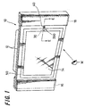
- FIG. 1 shows an embodiment of the electronic apparatus according to the present invention.
- Electronic equipment 10 is, for example, a plasma display apparatus having a plasma display panel (PDP) for displaying a picture.
- the plasma display panel is a display apparatus, for example, composed of two glasses between which gas such as helium, neon or the like is sealed to emit light when a voltage is applied thereto. Principles of light emission are the same as those of fluorescent light, but the plasma display panel has characteristics of higher contrast and a broader angle of field of view compared to other methods.
- the electronic equipment 10 can be used as a large-sized wall mounted type television set.
- the electronic equipment 10 includes: a chassis 12, a transparent front glass 14, speaker cabinets 16, 18, and a light reflex display apparatus 200.
- the speaker cabinets 16, 18 are provided at the positions on the left and right sides of the front glass 14, respectively.
- the chassis 12 secures the speaker cabinet 16, front glass 14, and speaker cabinet 18.
- a display portion of the plasma display panel, a drive circuit and others are accommodated.
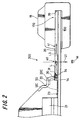
- FIG. 2 shows an example of a cross-sectional structure of the light reflex display apparatus 200 of the electronic equipment 10 taken by the E-E line in FIG. 1.
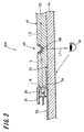
- FIG. 3 shows an enlarged part in the vicinity of the light reflex display apparatus 200 of FIG. 2.
- a front panel 20 is arrayed substantially in contact with the front glass.
- the front glass 14 is made of a light transmissive member, for example, a transparent flat panel of glass.
- the inside front panel 20 is disposed substantially in contact with the outside front glass 14 overlapped in parallel.
- the inside front panel 20 is made of a light transmissive member in the shape of a flat panel having light transmissivity, and the inside front panel 20 is made of, for example, a transparent resin panel.
- any one of transparent resin materials such as polycarbonate resin (PC), polymethylmethacrylate (PMMA), MS resin (methylmethacrylate styrene monomer copolymer), polypropylene (PP), transparent ABS (acrylonitrile-butadiene-styrene) resin, transparent polystyrene (PS), transparent epoxy resin, and other materials can be employed; however, other materials can be employed as well.
- PC polycarbonate resin
- PMMA polymethylmethacrylate
- MS resin methylmethacrylate styrene monomer copolymer
- PP polypropylene
- transparent ABS acrylonitrile-butadiene-styrene
- PS transparent polystyrene
- transparent epoxy resin and other materials
- the speaker cabinet 18 is provided in the vicinity of the inside front panel 20 and the front glass 14. Further, on the inside of the front glass 14 a plasma display portion 21 is provided in the chassis 12.
- the inside front panel 20 in the shape of a flat panel having light transmissivity can be a glass panel other than the above-described transparent resin panel.
- a light transmissive member in the shape of a flat panel having light transmissivity in each embodiment of the present invention may be transparent, translucent, or may be tinted as a matter of course.
- an inside end portion 20C of the front panel 20 is coupled with an end portion 12C of the chassis 12.
- a light emitting portion 30 is provided on the side of an inner surface 23 of the front glass 14 .
- a light emitting diode LED
- the light emitting portion 30 is disposed so as to oppose the side surface (also called end surface) 31 of the front panel 20. Accordingly, a light axis of the light emitting portion 30 is directed toward the side surface 31 and the direction of light axis of the light emitting 30 is parallel to the surface direction of the front panel 20.
- Light L emitted from the light emitting portion 30 enters the front panel 20 from the side surface 31 thereof and proceeds in the front panel 20 toward a light reflective portion 40.
- the light emitting portion 30 is held by a light emitting portion holder 33.
- the light emitting portion holder 33 is fixed on the side of, for example, the plasma display portion 21 and has a hole 34.
- the hole 34 of the light emitting portion holder 33 is provided to make light emitted from the light emitting portion 30 direct to the side of the later described light reflective portion 40 in the front panel 20, that is, to make the light exert its directivity. Accordingly, the light emitting holder 33 corresponds to a light directivity exerting member.
- the hole 34 is, for example, in circular shape and is provided opposing the side surface 31 of the front panel 20.
- the diameter of the hole 34 is approximately the same as that of the light emitting portion holder 33 or somewhat smaller than that.
- the light reflective portion 40 shown in FIGS. 3 and 4 is a recess formed on the side of an inner surface 41 of the front panel 20.
- the light reflective portion 40 is approximately a hemi-spherical recess.
- a satin-finished light dispersive portion 46 is formed on the hemi-spherical surface of the light reflective portion 40.
- a black coating portion 50 is formed as a cover member so that existence of the light emitting portion 30 is concealed from the observer M.
- the cover member can be printed, adhesive tape can be attached, or another member made of metal or plastic can be attached.
- the observer M when the transparent front glass 14 and the transparent front panel 20 are employed, the observer M shall not directly view the light emitting portion 30, because the black coating portion 50 interferes, as shown in FIG. 4A, with the observer's view, so that outer appearance and design of the electronic equipment will be preferable.
- the light reflective portion 40 provided on the inside front panel 20 is hemi-spherical, that is, semicircular in cross section, and for example such concave light reflective portion 40 is called a dimple-shaped portion.
- the black coating portion 50 is formed on the inside surface 23 of the outside front glass 14.
- the black coating portion 50 can be formed on the side of an outer surface 48.
- light L reflected by the light reflective portion 40 can be seen by an observer as if approximately semicircular light L were generated at the transparent front panel 20 and the front glass 14 as shown in FIG. 4B.
- Color of the light emitted from the light emitting portion 30 shown in FIG. 3 is for example green, blue, red or the like.
- light L1 can functionally display for an observer M the state in which power of the electronic equipment shown in FIG. 1 is ON.
- light L1 can functionally display for the observer M a picture turn-off mode (the state in which only sound is output without displaying a picture) in electronic equipment shown in, for example, FIG. 1.
- light L1 can functionally display the state in which the electronic equipment shown in FIG. 1 is in a standby mode.
- the depth of a recess constituting the light reflective portion 40 can be arbitrarily selected. Further, the dimensions of the light reflective portion 40 can be set arbitrarily.
- a part 150 of the front panel 20 and front glass 14 is held by a light leakage prevention portion 170 of the speaker cabinet 18 to be covered and secured.
- the light reflective portion 40 is provided at a position between the part 150 and the light emitting portion 30. After light L emitted from the light emitting portion 30 is reflected by the light reflective portion 40 and becomes light L1, remaining light L3 that has not been reflected proceeds along the surface direction of the front panel 20 and reaches the side surface 39 of the part 150.
- light L3 can be prevented from leaking from the side surface 39 of the front panel 20 so that the observer' M may not perceive the leaking light L3, whereby light L1 reflected by the light reflective portion 40 may not be interfered by the leaking light L3 and outer appearance and design of the electronic equipment is improved.
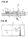
- the difference between the embodiment shown in FIG. 5 and the embodiment shown in FIGS. 2 through 4 is the shape of the light reflective portion 40.
- the light reflective portion 40 in FIG. 5 is a recess formed on the inside surface 41 of the inside front panel 20 and has the circular-arc cross section.
- the shape in detail of the portion 55 having a circular-arc cross section is shown in FIGS. 6A and 6B.
- the portion 55 having a circular-arc cross section extends to a portion 57 having a vertical cross section.
- the vertical portion 57 is perpendicularly formed with respect to the flat inside surface 41 of the front panel 20. Accordingly, as shown in FIG. 6B, the light reflective portion 40 is a recess having a part of a cylindrical surface.
- a point P1 is determined at half the depth of the front panel 20 and a line L1 is drawn at an angle of 45° from the point P1 to the inside surface 41.
- the line L1 is a straight line connecting the point P1 and a point P2.
- Another line L2 is drawn at an angle further inclined 15°
- a line L3 is drawn at an angle further inclined 15°.
- the observer M may perceive the rectangular light L1 as if the light were emitted from the light emitting portion existing on the spot.
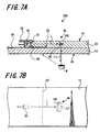
- FIGS. 7A and 7B further another embodiment of the present invention will be described.
- FIGS. 7A and 7B the same numerals and symbols as those in the embodiment shown in FIGS. 4 are given to corresponding portions, and the explanation thereof is also employed.
- the difference between the embodiment shown in FIG. 7 and the embodiment shown in FIG. 4 is the shape of the light reflective portion 40.
- the light reflective portion 40 in FIG. 7 has an inclined surface portion 100.
- the light dispersive portion 46 is formed on the inclined surface portion 100.
- the inclined surface portion 100 is provided at the bottom of a recess formed on the inside surface 41 of the front panel 20.
- the angle of inclination of the inclined surface portion 100 is, for example, 45° with respect to the flat inside surface 41.
- the observer M may perceive the rectangular light L1 as if the light were emitted from the light emitting portion existing on the spot.
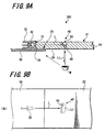
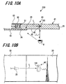
- FIGS. 8 through 10 shows further another embodiment of the present invention.
- the embodiment shown in FIG. 8 has one front panel, which is different from the embodiment shown in FIG. 4 having two panels. Accordingly, one front panel 20 is employed and on the inside surface 41 of the front panel 20 a light reflective portion 40 in the shape of a recess is formed.
- the light reflective portion 40 has a hemi-spherical shape in which a light dispersive portion 46 is formed.
- a black coating portion 50 is provided, for example, on the outside surface 49 of the front panel 20.
- the difference between the embodiment shown in FIG. 9 and the embodiment shown in FIG. 8 is the shape of the light reflective portion 40.
- the shape of the light reflective portion 40 in FIG. 9 is the same as that shown in FIG. 5.
- FIG. 10 only one front panel 20 is employed similarly to the embodiments shown in FIGS. 8 and 9, while the shape of the light reflective portion 40 is different.
- the shape of the light reflective portion 40 shown in FIG. 10 is the same as that of the light reflective portion 40 shown in FIG. 7.
- the electronic equipment 10 shown in FIG. 1 has the light reflex display apparatus 200 composed of the light reflective portion 40 in the front panel 20 and the light emitting portion 30.
- the light emitting portion 30 is disposed opposing the side surface (also called end surface) 31 of the front panel 20.
- Light L emitted from the light emitting portion 30 is reflected by the light reflective portion 40, so that an observer M being on the outside of the front panel 20 may perceive the reflected light as if the light were emitted from a light emitting portion existing on the spot and were floating in midair. Accordingly, since light L entered as described above is reflected by the light reflective portion 40 and is dispersed by a light dispersive portion, the observer M may perceive that the light emitting portion 30 itself illuminates on the spot, when watching the reflected light L1.
- color of light L1 reflected as shown in FIG. 2 can be varied. With color of the reflected light L1 set to green, red, blue or the like, light L1 having the selected color can display a predetermined function of the electronic equipment for the observer.
- the shape of the light reflective portion 40 is not limited to the above-described dimple shape, inclined surface shape, or shape having a part of cylindrical surface, and other shapes can be employed without question.
- a satin-finished surface is formed on a portion having such cross section as semi-circular shape, inclined surface shape, or circular-arc shape of the light reflective portion 40; however, other surfaces than a satin-finished one can also be employed.
- the light reflective portion 40 is formed on the side of the inside surface 41 of the front panel 20, as shown in FIG. 2; however, the present invention is not limited thereto and without question the light reflective portion may be formed on the side of the outside surface of the front panel 20.
- the front panel 20 constituting a light transmissive member can be formed of a transparent glass panel or a transparent resin panel. Further, such light transmissive member can be transparent and unpigmented materials, or if necessary, can be pigmented materials as a matter of course.
- a plasma display panel is employed as an example of electronic equipment according to the present invention.
- electronic equipment according to the present invention is not limited thereto, and various pieces of equipment requiring a front panel that is transparent or has light transmissivity, such as a display apparatus including a cathode-ray tube, a digital still camera, a digital video camera, a portable information terminal, a mobile phone unit, game equipment and other pieces of equipments are included as a matter of course.
Landscapes
- Physics & Mathematics (AREA)
- General Physics & Mathematics (AREA)
- Optics & Photonics (AREA)
- Engineering & Computer Science (AREA)
- Theoretical Computer Science (AREA)
- Illuminated Signs And Luminous Advertising (AREA)
- Devices For Indicating Variable Information By Combining Individual Elements (AREA)
- Planar Illumination Modules (AREA)
Applications Claiming Priority (3)
| Application Number | Priority Date | Filing Date | Title |
|---|---|---|---|
| JP2002221126A JP2004061922A (ja) | 2002-07-30 | 2002-07-30 | 光反射表示方法、光反射表示装置および電子機器 |
| JP2002221126 | 2002-07-30 | ||
| PCT/JP2003/009679 WO2004012174A1 (ja) | 2002-07-30 | 2003-07-30 | 光反射表示方法、光反射表示装置および電子機器 |
Publications (2)
| Publication Number | Publication Date |
|---|---|
| EP1445751A1 true EP1445751A1 (de) | 2004-08-11 |
| EP1445751A4 EP1445751A4 (de) | 2005-05-11 |
Family
ID=31184835
Family Applications (1)
| Application Number | Title | Priority Date | Filing Date |
|---|---|---|---|
| EP03771431A Withdrawn EP1445751A4 (de) | 2002-07-30 | 2003-07-30 | Lichtreflektionsanzeigeverfahren und -einrichtung und elektronische vorrichtung |
Country Status (6)
| Country | Link |
|---|---|
| US (1) | US20040233127A1 (de) |
| EP (1) | EP1445751A4 (de) |
| JP (1) | JP2004061922A (de) |
| KR (1) | KR101032169B1 (de) |
| CN (1) | CN100403357C (de) |
| WO (1) | WO2004012174A1 (de) |
Families Citing this family (15)
| Publication number | Priority date | Publication date | Assignee | Title |
|---|---|---|---|---|
| JP4239020B2 (ja) | 2004-07-12 | 2009-03-18 | ソニー株式会社 | フラットディスプレイパネル装置 |
| JP4691917B2 (ja) * | 2004-07-12 | 2011-06-01 | ソニー株式会社 | ディスプレイ機器 |
| JP2006058569A (ja) * | 2004-08-19 | 2006-03-02 | Sony Corp | パネル型表示装置 |
| KR100637171B1 (ko) * | 2004-09-10 | 2006-10-20 | 삼성에스디아이 주식회사 | 플라즈마 디스플레이 패널 장치 |
| JP2006201509A (ja) * | 2005-01-20 | 2006-08-03 | Sony Corp | パネル型表示装置 |
| JP4735348B2 (ja) * | 2006-03-10 | 2011-07-27 | ソニー株式会社 | 照明装置及び映像表示装置 |
| JP4725792B2 (ja) | 2006-04-11 | 2011-07-13 | ソニー株式会社 | 電子機器 |
| JP2007279577A (ja) | 2006-04-11 | 2007-10-25 | Sony Corp | 電子機器 |
| JP2008299116A (ja) * | 2007-05-31 | 2008-12-11 | Fujikura Ltd | 機器 |
| US8167253B2 (en) * | 2008-06-02 | 2012-05-01 | Sony Corporation | Flat panel TV stand providing floating appearance |
| WO2010113535A1 (ja) * | 2009-04-02 | 2010-10-07 | 株式会社ソニー・コンピュータエンタテインメント | 電子機器 |
| US8861198B1 (en) | 2012-03-27 | 2014-10-14 | Amazon Technologies, Inc. | Device frame having mechanically bonded metal and plastic |
| US8922983B1 (en) * | 2012-03-27 | 2014-12-30 | Amazon Technologies, Inc. | Internal metal support structure for mobile device |
| WO2014125523A1 (ja) * | 2013-02-12 | 2014-08-21 | パナソニック株式会社 | 表示装置 |
| CN117178266A (zh) * | 2021-04-27 | 2023-12-05 | 三星电子株式会社 | 包括发光设备的电子装置 |
Family Cites Families (19)
| Publication number | Priority date | Publication date | Assignee | Title |
|---|---|---|---|---|
| JPS553704U (de) * | 1978-06-21 | 1980-01-11 | ||
| US4929866A (en) * | 1987-11-17 | 1990-05-29 | Mitsubishi Cable Industries, Ltd. | Light emitting diode lamp |
| JP2763138B2 (ja) * | 1989-06-23 | 1998-06-11 | 株式会社東芝 | 携帯形情報機器 |
| US5335192A (en) * | 1990-04-11 | 1994-08-02 | Nippon Steel Corporation | Portable computer with pivotally mounted cover |
| US5291851A (en) * | 1990-06-29 | 1994-03-08 | Yazaki Corporation | Gauge for automobile |
| US5406268A (en) * | 1991-06-12 | 1995-04-11 | Iqv Corporation | Portable microcomputer with power-sparing system of illuminated indicators |
| DE69217177T2 (de) * | 1991-11-28 | 1997-05-15 | Enplas Corp | Flächenartige Lichtquelle |
| JPH0651129A (ja) * | 1992-07-27 | 1994-02-25 | Inoue Denki Kk | 照明装置 |
| JPH07201215A (ja) * | 1993-12-28 | 1995-08-04 | Toshiba Lighting & Technol Corp | 誘導灯 |
| JPH08286630A (ja) * | 1995-03-20 | 1996-11-01 | Kwang-Won Kim | 電光装置 |
| GB9524115D0 (en) * | 1995-11-24 | 1996-01-24 | Varintelligent Bvi Ltd | A display device |
| JP2945318B2 (ja) * | 1996-01-17 | 1999-09-06 | スタンレー電気株式会社 | 面光源装置 |
| JPH09203811A (ja) * | 1996-01-26 | 1997-08-05 | Nec Home Electron Ltd | バックライト装置 |
| US5930710A (en) * | 1996-03-07 | 1999-07-27 | Telefonaktiebolaget L M Ericsson | Control/pilot channel reselection between cells belonging to different registration areas |
| JPH09258678A (ja) * | 1996-03-26 | 1997-10-03 | Idec Izumi Corp | ディスプレイユニット |
| JP3633177B2 (ja) * | 1997-01-23 | 2005-03-30 | カシオ計算機株式会社 | 化粧部材の製造方法 |
| KR100240288B1 (ko) * | 1997-01-24 | 2000-01-15 | 박강정 | 장식용 발광장치 |
| JP2001075514A (ja) * | 1999-06-28 | 2001-03-23 | Shinsei Sangyo Kk | 自発光型サイン表示装置 |
| TW461533U (en) * | 2000-05-11 | 2001-10-21 | Asustek Comp Inc | Status display device of notebook computer |
-
2002
- 2002-07-30 JP JP2002221126A patent/JP2004061922A/ja active Pending
-
2003
- 2003-07-30 US US10/491,095 patent/US20040233127A1/en not_active Abandoned
- 2003-07-30 CN CNB038013673A patent/CN100403357C/zh not_active Expired - Fee Related
- 2003-07-30 KR KR1020047004336A patent/KR101032169B1/ko not_active Expired - Fee Related
- 2003-07-30 EP EP03771431A patent/EP1445751A4/de not_active Withdrawn
- 2003-07-30 WO PCT/JP2003/009679 patent/WO2004012174A1/ja not_active Ceased
Also Published As
| Publication number | Publication date |
|---|---|
| EP1445751A4 (de) | 2005-05-11 |
| KR101032169B1 (ko) | 2011-05-02 |
| JP2004061922A (ja) | 2004-02-26 |
| CN100403357C (zh) | 2008-07-16 |
| KR20050023205A (ko) | 2005-03-09 |
| US20040233127A1 (en) | 2004-11-25 |
| CN1578974A (zh) | 2005-02-09 |
| WO2004012174A1 (ja) | 2004-02-05 |
Similar Documents
| Publication | Publication Date | Title |
|---|---|---|
| EP1445751A1 (de) | Lichtreflektionsanzeigeverfahren und -einrichtung und elektronische vorrichtung | |
| US8390759B2 (en) | Electronic device display structures with controlled chassis reflections | |
| EP3012686B1 (de) | Lichtemittierende vorrichtung für anzeigeeinheit | |
| US9599768B2 (en) | Surface light source device having frame with light absorbing and reflecting portions | |
| US7847877B2 (en) | Panel | |
| US8864358B2 (en) | Surface light source device and frame used therein | |
| WO1998013709A1 (en) | Illuminating device and display using the device | |
| KR20170005537A (ko) | 디스플레이 장치의 백 라이트 유닛 및 디스플레이 장치 | |
| KR20150049859A (ko) | 베젤 가림 부재를 가진 디스플레이 장치 | |
| MXPA05010248A (es) | Sistema y metodo para iluminar una pantalla de modulador interferometrico. | |
| KR20160141478A (ko) | 디스플레이 장치의 월 마운트 플레이트 및 디스플레이 장치 | |
| JP6945448B2 (ja) | 発光装置、表示装置および照明装置 | |
| CN212181213U (zh) | 背光模组、显示屏组件以及电子装置 | |
| JP2004361664A (ja) | パネル型表示装置 | |
| US10788612B2 (en) | Light-emitting unit, display apparatus, and lighting apparatus | |
| JP4001173B2 (ja) | 画像表示装置 | |
| JP2007316653A (ja) | 画像表示装置 | |
| JP4168840B2 (ja) | パネル型表示装置 | |
| KR102477040B1 (ko) | 디스플레이 장치 및 전자 장치 | |
| CN222636435U (zh) | 背光模组及显示装置 | |
| US12222635B1 (en) | Image projection and display apparatus and method | |
| CN115802846B (zh) | 显示装置及电子设备 | |
| CN220796260U (zh) | 展示机 | |
| JP6961754B2 (ja) | 表示装置および発光装置 | |
| CN208691306U (zh) | 移动终端及其感光装置 |
Legal Events
| Date | Code | Title | Description |
|---|---|---|---|
| PUAI | Public reference made under article 153(3) epc to a published international application that has entered the european phase |
Free format text: ORIGINAL CODE: 0009012 |
|
| 17P | Request for examination filed |
Effective date: 20040421 |
|
| AK | Designated contracting states |
Kind code of ref document: A1 Designated state(s): AT BE BG CH CY CZ DE DK EE ES FI FR GB GR HU IE IT LI LU MC NL PT RO SE SI SK TR |
|
| A4 | Supplementary search report drawn up and despatched |
Effective date: 20050329 |
|
| RIC1 | Information provided on ipc code assigned before grant |
Ipc: 7G 02B 6/00 A |
|
| RBV | Designated contracting states (corrected) |
Designated state(s): DE ES FR GB |
|
| 17Q | First examination report despatched |
Effective date: 20060704 |
|
| STAA | Information on the status of an ep patent application or granted ep patent |
Free format text: STATUS: THE APPLICATION IS DEEMED TO BE WITHDRAWN |
|
| 18D | Application deemed to be withdrawn |
Effective date: 20150203 |