EP1446821B1 - Lampe fluorescente auto-ballastee compacte - Google Patents
Lampe fluorescente auto-ballastee compacte Download PDFInfo
- Publication number
- EP1446821B1 EP1446821B1 EP02778093A EP02778093A EP1446821B1 EP 1446821 B1 EP1446821 B1 EP 1446821B1 EP 02778093 A EP02778093 A EP 02778093A EP 02778093 A EP02778093 A EP 02778093A EP 1446821 B1 EP1446821 B1 EP 1446821B1
- Authority
- EP
- European Patent Office
- Prior art keywords
- lamp
- tube
- arc tube
- glass tube
- arc
- Prior art date
- Legal status (The legal status is an assumption and is not a legal conclusion. Google has not performed a legal analysis and makes no representation as to the accuracy of the status listed.)
- Expired - Lifetime
Links
- 239000011521 glass Substances 0.000 claims description 231
- QSHDDOUJBYECFT-UHFFFAOYSA-N mercury Chemical compound [Hg] QSHDDOUJBYECFT-UHFFFAOYSA-N 0.000 claims description 69
- 229910052753 mercury Inorganic materials 0.000 claims description 40
- 229910000497 Amalgam Inorganic materials 0.000 claims description 28
- 229920002050 silicone resin Polymers 0.000 claims description 27
- 230000008961 swelling Effects 0.000 claims description 9
- 229910052751 metal Inorganic materials 0.000 claims description 2
- 239000002184 metal Substances 0.000 claims description 2
- 229920005989 resin Polymers 0.000 claims description 2
- 239000011347 resin Substances 0.000 claims description 2
- 239000005060 rubber Substances 0.000 claims 1
- 238000010276 construction Methods 0.000 description 63
- 230000004907 flux Effects 0.000 description 63
- 238000000034 method Methods 0.000 description 26
- 238000005259 measurement Methods 0.000 description 22
- 230000000630 rising effect Effects 0.000 description 19
- 238000004519 manufacturing process Methods 0.000 description 15
- 238000004804 winding Methods 0.000 description 13
- 230000015556 catabolic process Effects 0.000 description 9
- 238000006731 degradation reaction Methods 0.000 description 9
- 239000007789 gas Substances 0.000 description 9
- 238000002474 experimental method Methods 0.000 description 8
- 230000003287 optical effect Effects 0.000 description 7
- IJGRMHOSHXDMSA-UHFFFAOYSA-N Atomic nitrogen Chemical compound N#N IJGRMHOSHXDMSA-UHFFFAOYSA-N 0.000 description 6
- 230000006872 improvement Effects 0.000 description 6
- 230000008569 process Effects 0.000 description 6
- 230000004048 modification Effects 0.000 description 5
- 238000012986 modification Methods 0.000 description 5
- 230000007423 decrease Effects 0.000 description 4
- 229910016314 BiPbSn Inorganic materials 0.000 description 3
- OAICVXFJPJFONN-UHFFFAOYSA-N Phosphorus Chemical compound [P] OAICVXFJPJFONN-UHFFFAOYSA-N 0.000 description 3
- 229910045601 alloy Inorganic materials 0.000 description 3
- 239000000956 alloy Substances 0.000 description 3
- 239000000463 material Substances 0.000 description 3
- 229910052757 nitrogen Inorganic materials 0.000 description 3
- 238000004904 shortening Methods 0.000 description 3
- XKRFYHLGVUSROY-UHFFFAOYSA-N Argon Chemical compound [Ar] XKRFYHLGVUSROY-UHFFFAOYSA-N 0.000 description 2
- 239000000853 adhesive Substances 0.000 description 2
- 230000001070 adhesive effect Effects 0.000 description 2
- 230000008878 coupling Effects 0.000 description 2
- 238000010168 coupling process Methods 0.000 description 2
- 238000005859 coupling reaction Methods 0.000 description 2
- 230000003247 decreasing effect Effects 0.000 description 2
- 238000009826 distribution Methods 0.000 description 2
- 238000010438 heat treatment Methods 0.000 description 2
- 229910052738 indium Inorganic materials 0.000 description 2
- APFVFJFRJDLVQX-UHFFFAOYSA-N indium atom Chemical compound [In] APFVFJFRJDLVQX-UHFFFAOYSA-N 0.000 description 2
- 229920003002 synthetic resin Polymers 0.000 description 2
- 239000000057 synthetic resin Substances 0.000 description 2
- 229910052721 tungsten Inorganic materials 0.000 description 2
- -1 BiIN Inorganic materials 0.000 description 1
- DKPFZGUDAPQIHT-UHFFFAOYSA-N Butyl acetate Natural products CCCCOC(C)=O DKPFZGUDAPQIHT-UHFFFAOYSA-N 0.000 description 1
- 229910052684 Cerium Inorganic materials 0.000 description 1
- 229910052693 Europium Inorganic materials 0.000 description 1
- 229910001477 LaPO4 Inorganic materials 0.000 description 1
- 229910052771 Terbium Inorganic materials 0.000 description 1
- HCHKCACWOHOZIP-UHFFFAOYSA-N Zinc Chemical compound [Zn] HCHKCACWOHOZIP-UHFFFAOYSA-N 0.000 description 1
- 230000002411 adverse Effects 0.000 description 1
- 229910052786 argon Inorganic materials 0.000 description 1
- 239000011324 bead Substances 0.000 description 1
- 229910052797 bismuth Inorganic materials 0.000 description 1
- JCXGWMGPZLAOME-UHFFFAOYSA-N bismuth atom Chemical compound [Bi] JCXGWMGPZLAOME-UHFFFAOYSA-N 0.000 description 1
- 230000008859 change Effects 0.000 description 1
- 239000011248 coating agent Substances 0.000 description 1
- 238000000576 coating method Methods 0.000 description 1
- 238000007796 conventional method Methods 0.000 description 1
- 230000000593 degrading effect Effects 0.000 description 1
- 230000003111 delayed effect Effects 0.000 description 1
- 238000013461 design Methods 0.000 description 1
- 230000000694 effects Effects 0.000 description 1
- 239000012530 fluid Substances 0.000 description 1
- FUZZWVXGSFPDMH-UHFFFAOYSA-N hexanoic acid Chemical compound CCCCCC(O)=O FUZZWVXGSFPDMH-UHFFFAOYSA-N 0.000 description 1
- 239000007788 liquid Substances 0.000 description 1
- 229910052748 manganese Inorganic materials 0.000 description 1
- 239000000203 mixture Substances 0.000 description 1
- 238000000465 moulding Methods 0.000 description 1
- 229910052754 neon Inorganic materials 0.000 description 1
- GKAOGPIIYCISHV-UHFFFAOYSA-N neon atom Chemical compound [Ne] GKAOGPIIYCISHV-UHFFFAOYSA-N 0.000 description 1
- 230000002093 peripheral effect Effects 0.000 description 1
- 229910052761 rare earth metal Inorganic materials 0.000 description 1
- 150000002910 rare earth metals Chemical class 0.000 description 1
- 229920003051 synthetic elastomer Polymers 0.000 description 1
- 239000005061 synthetic rubber Substances 0.000 description 1
- WFKWXMTUELFFGS-UHFFFAOYSA-N tungsten Chemical compound [W] WFKWXMTUELFFGS-UHFFFAOYSA-N 0.000 description 1
- 239000010937 tungsten Substances 0.000 description 1
- XLYOFNOQVPJJNP-UHFFFAOYSA-N water Substances O XLYOFNOQVPJJNP-UHFFFAOYSA-N 0.000 description 1
- 229910052725 zinc Inorganic materials 0.000 description 1
- 239000011701 zinc Substances 0.000 description 1
Images


Classifications
-
- C—CHEMISTRY; METALLURGY
- C03—GLASS; MINERAL OR SLAG WOOL
- C03B—MANUFACTURE, SHAPING, OR SUPPLEMENTARY PROCESSES
- C03B23/00—Re-forming shaped glass
- C03B23/04—Re-forming tubes or rods
- C03B23/06—Re-forming tubes or rods by bending
-
- H—ELECTRICITY
- H01—ELECTRIC ELEMENTS
- H01J—ELECTRIC DISCHARGE TUBES OR DISCHARGE LAMPS
- H01J61/00—Gas-discharge or vapour-discharge lamps
- H01J61/02—Details
- H01J61/12—Selection of substances for gas fillings; Specified operating pressure or temperature
- H01J61/18—Selection of substances for gas fillings; Specified operating pressure or temperature having a metallic vapour as the principal constituent
- H01J61/20—Selection of substances for gas fillings; Specified operating pressure or temperature having a metallic vapour as the principal constituent mercury vapour
-
- H—ELECTRICITY
- H01—ELECTRIC ELEMENTS
- H01J—ELECTRIC DISCHARGE TUBES OR DISCHARGE LAMPS
- H01J61/00—Gas-discharge or vapour-discharge lamps
- H01J61/02—Details
- H01J61/30—Vessels; Containers
- H01J61/32—Special longitudinal shape, e.g. for advertising purposes
- H01J61/327—"Compact"-lamps, i.e. lamps having a folded discharge path
-
- H—ELECTRICITY
- H01—ELECTRIC ELEMENTS
- H01J—ELECTRIC DISCHARGE TUBES OR DISCHARGE LAMPS
- H01J61/00—Gas-discharge or vapour-discharge lamps
- H01J61/02—Details
- H01J61/52—Cooling arrangements; Heating arrangements; Means for circulating gas or vapour within the discharge space
-
- H—ELECTRICITY
- H01—ELECTRIC ELEMENTS
- H01J—ELECTRIC DISCHARGE TUBES OR DISCHARGE LAMPS
- H01J9/00—Apparatus or processes specially adapted for the manufacture, installation, removal, maintenance of electric discharge tubes, discharge lamps, or parts thereof; Recovery of material from discharge tubes or lamps
- H01J9/24—Manufacture or joining of vessels, leading-in conductors or bases
- H01J9/245—Manufacture or joining of vessels, leading-in conductors or bases specially adapted for gas discharge tubes or lamps
- H01J9/247—Manufacture or joining of vessels, leading-in conductors or bases specially adapted for gas discharge tubes or lamps specially adapted for gas-discharge lamps
Definitions
- the present invention relates to a compact self-ballasted fluorescent lamp that includes a bent arc tube, and to a manufacturing method for the arc tube.
- compact self-ballasted fluorescent lamps that exhibit high luminous efficiency and long life are calling attentions as alternative light sources to incandescent lamps.
- Compact self-ballasted fluorescent lamps (hereafter simply referred to as "lamps") have bent arc tubes. Roughly two design types of such lamps are available, namely, lamps having globes for covering arc tubes, and lamps not having globes for covering arc tubes.
- a lamp having a globe is referred to as a "globe-type lamp” and a lamp not having a globe is referred to as a "non globe-type lamp”.
- a globe-type lamp and a non globe-type lamp lies not only in the presence of a globe, but also in the form of mercury enclosed within an arc tube.
- mercury is enclosed within its arc tube in the form of an alloy containing bismuth (Bi), indium (In), tin(Sn), and the like, i.e., in the form of an amalgam.
- mercury is enclosed within its arc tube not in the form of an amalgam but in a single form.
- a globe-type lamp too, mercury used to be enclosed within its arc tube in the single form.
- a globe-type lamp in which mercury is enclosed in the single form has the following problem. When such a globe-type lamp is lit, heat is trapped in its globe covering the arc tube, causing the temperature of the arc tube to increase excessively. Along with this, a mercury vapor pressure within the arc tube increases, thereby greatly degrading the luminous efficiency of the lamp.
- mercury is still enclosed within its arc tube in the single form because the temperature of the arc tube does not increase much during lighting and so only subtle degradation of the luminous efficiency occurs.
- US 6 064 155 A discloses a compact fluorescent lamp designed to imitate an incandescent lamp in size, shape and luminosity.
- the lamp includes a bulbous envelope having an external shape of an incandescent lamp on a standard Edison-type base that enables it to be substituted for standard 60, 75 and 100 W incandescent lamps.
- a low-pressure fluorescent lamp having a coiled tubular envelope with an outer diameter less than about 7 mm, an inner diameter between about 1 and 5 mm, and a length between about 50 and 100 cm is wound in a coil around the axis of the bulbous envelope and is disposed within the bulbous envelope.
- the tubular envelope is formed of soft glass and has a fluorescent phosphor coating disposed on the inner surfaces.
- Electrodes with external electrical contacts are disposed at each end of the envelope.
- a ballast is disposed within the bulbous envelope. The ballast is electrically connected to the lamp, whereby to control current in the fluorescent lamp.
- a heat shield is disposed between the lamp and the ballast to thermally isolate the lamp from the ballast, whereby heat from the lamp will not adversely affect the ballast.
- JP 58 198849 A relates to a non-linear fluorescent lamp charged with mercury and rare gas and provided with electrodes at both ends thereof that is supported by a mounting structure made of resin or the like and constituted so as to be tightly enclosed by a photo-transmissible globe. Also, a heat conductive medium is interposed partially in the space between the lamp and the globe and the lamp is thermally united with said globe. Further, the shortest distance between this non-linear fluorescent lamp and the globe is set up so as to be in a range of 0.5-1.6mm.
- EP 0918352 A1 relates to a self-ballasted fluorescent lamp which is equivalent to a typical light bulb.
- the self-ballasted fluorescent lamp includes a cover, a lighting circuit, an arc tube, a base and a globe and formed into a shape whose outline dimensions are nearly identical to the standard dimensions of a typical light bulb.
- the arc tube is comprised of a plurality of U-shaped bent bulbs which have an inner tube diameter ranging from 6 to 9 mm and arranged in parallel with one another.
- the arc tube is designed such that the total luminous flux is not less than 700 lm with a lamp efficiency of not less than 60 lm/W when the lamp is lit at the lamp power of 7 to 15 W.
- An envelope comprising the cover and the globe has a height ranging from 110 to 125 mm, including the height of the base.
- the present invention aims to provide a compact self-ballasted fluorescent lamp with higher luminous efficiency than conventional compact lamps, and with improved luminous flux rising characteristics at lamp startup equivalent to those of general fluorescent lamps.
- the amalgam form of mercury can be at least one amalgam selected from the group consisting of ZnHg, FeHg, BiHg, BiSnHg, and SnHg.
- the luminous flux rising characteristics equivalent to those of a fluorescent lamp for general lighting can be obtained.
- the inner tube diameter of the glass tube is set in the range of 5 to 9mm inclusive, and therefore, an optical path on which ultraviolet light emitted from mercury atoms travels to the tube wall of the arc tube can be shortened.
- the temperature at which the arc tube achieves the maximum luminous flux can be increased. Therefore, a difference between the temperature at which the arc tube achieves the maximum luminous flux and the temperature of the arc tube during lighting of the lamp can be narrowed. Accordingly, the luminous efficiency higher than that for a conventional lamp can be obtained.
- the electrodes may be provided at both ends of the glass tube, and when an inner diameter " ⁇ i (mm)" of the glass tube and a distance "Le (mm)” between the electrodes are expressed as rectangular coordinates ( ⁇ i, Le), values for the rectangular coordinates ( ⁇ i, Le) are within a range surrounded by points (5.0, 370), (7.4, 275), (9.0, 290), (9.0, 360), and (5.0, 690).
- the luminous efficiency can be improved to a level equivalent to or higher than the conventional lamp. Also, the lamp life of 6000 hours can be ensured. Further, the lamp can be made as compact as or more compact than the conventional lamp as an alternative to a 60W incandescent lamp.
- the electrodes may be provided at both ends of the glass tube, and when an inner diameter " ⁇ i (mm)" of the glass tube and a distance "Le (mm)” between the electrodes are expressed as rectangular coordinates ( ⁇ i, Le), values for the rectangular coordinates ( ⁇ i, Le) are within a range surrounded by points (5.0, 700), (7.4, 530), (9.0, 560), (9.0, 620), and (5.0, 930).
- the luminous efficiency can be improved to a level equivalent to or higher than the conventional lamp. Also, the lamp life of 6000 hours can be ensured. Further, the lamp can be made as compact as or more compact than the conventional lamp as an alternative to a 100W incandescent lamp.
- the electrodes may be provided at both ends of the glass tube, and when an inner diameter " ⁇ i (mm)" of the glass tube and a distance "Le (mm)” between the electrodes are expressed as rectangular coordinates ( ⁇ i, Le), values for the rectangular coordinates ( ⁇ i, Le) are within a range surrounded by points (5.0, 800), (7.4, 570), (9.0, 600), (9.0, 670), and (5.0, 1000).
- the luminous efficiency can be improved to a level equivalent to or higher than the conventional high-luminous-flux type 23W lamp. Also, the lamp life of 6000 hours can be ensured. Further, the lamp can be made as compact as or more compact than the conventional high-luminous-flux type 23W lamp.
- the electrodes may be provided at both ends of the glass tube, and when an inner diameter " ⁇ i (mm) " of the glass tube and a distance "Le (mm)" between the electrodes are expressed as rectangular coordinates ( ⁇ i, Le), values for the rectangular coordinates ( ⁇ i, Le) are within a range surrounded by points (5.0, 270), (7.4, 200), (9.0, 230), (9.0, 320), and (5.0, 590).
- the luminous efficiency can be improved to a level equivalent to or higher than a conventional lamp. Also, the lamp life of 6000 hours can be ensured. Further, the lamp can be made as compact as or more compact than the conventional 7W lamp.
- the double-spiral structure is made up of a turning part, a first spiral part, and a second spiral part, the turning part being positioned substantially in a middle between both ends of the glass tube, the first spiral part starting from one end of the glass tube and being wound around an axis toward the turning part, the second spiral part starting from the turning part and being wound around the axis toward the other end of the glass tube, and the glass tube is connected to the globe in a vicinity of the turning part thereof, via the heat-conductive member.
- the coolest point of the arc tube is formed in a vicinity of the turning part during lighting of the lamp. Heat in this coolest point part can be conducted to the globe via the heat-conductive member. Therefore, the temperature of the coolest point of the arc tube can be effectively lowered.
- the turning part of the glass tube has a projection extending toward the globe.
- an area where the arc tube and the heat-conductive member are connected with each other can be increased.
- a compact self-ballasted fluorescent lamp including an arc tube that is made by a spirally bent glass tube, wherein a cross section of the glass tube at an inner circumference thereof is in a non-circular shape.
- the glass tube is spirally wound around an axis, and a first diameter of the cross section at the inner circumference is smaller than a second diameter of the cross section at the inner circumference, the first diameter being in a direction substantially perpendicular to the axis, the second diameter being in a direction substantially parallel to the axis.
- the cross section of the glass tube may be in a substantially oval-shape, or the cross section of the glass tube is in a V-shape.
- the first diameter is smaller than the second diameter.
- an optical path on which ultraviolet light emitted form mercury atoms travels to the tube wall of the arc tube can be shortened, and also, the temperature at which the arc tube achieves the maximum luminous flux can be increased, as compared with the case where the inner circumference of the glass tube is in such a circular shape having the diameter being equal to the second diameter. Therefore, a difference between the temperature at which the arc tube achieves the maximum luminous flux and the temperature of the arc tube during lighting of the lamp can be narrowed, and so the luminous efficiency can be improved.
- the inner circumference of the first diameter is in the direction substantially perpendicular to the axis of the arc tube, the inner circumference part (positioned at the axis side) of the oval-shaped cross section of the glass tube is more distant from the axis than the inner circumference part (positioned at the axis side) of a circular-shaped cross section of the glass tube. Therefore, the electrode distance can be lengthened and the luminous efficiency can be improved, as compared with the case where the glass tube has a circular-shaped cross section.
- a value for “D2” may be in a range of 5 to 9mm inclusive, and a value for "D1” is not less than 3mm and is less than the value for "D2".
- an optical path on which ultraviolet light emitted from mercury atoms travels to the tube wall of the arc tube can be shortened, and the temperature at which the arc tube achieves the maximum luminous flux can be increased. Therefore, even if the temperature of the arc tube increases during lighting of the lamp, a decrease in the luminous efficiency can be suppressed. Also, the electrodes can be easily placed in the arc tube by utilizing the second diameter.
- the arc tube may include electrodes that are provided at both ends of the glass tube, and when the first diameter "D1 (mm)" and a distance "Le (mm)” between the electrodes are expressed as rectangular coordinates (D1, Le), values for the rectangular coordinates (D1, Le) are within a range surrounded by points (3.0, 445), (7.4, 275), (9.0, 290), (9.0, 360), and (3.0, 855).
- the luminous efficiency can be improved to a level equivalent to or higher than a conventional lamp. Also, the lamp life of 6000 hours can be ensured. Further, the lamp can be made as compact as or more compact than the conventional lamp.
- the arc tube may include electrodes that are provided at both ends of the glass tube, and when the first diameter "D1 (mm)" and a distance “Le (mm)” between the electrodes are expressed as rectangular coordinates (D1, Le), values for the rectangular coordinates (D1, Le) are within a range surrounded by points (3.0, 840), (7.4, 530), (9.0, 560), (9.0, 620), and (3.0, 1085).
- the luminous efficiency can be improved to a level equivalent to or higher than the conventional lamp. Also, the lamp life of 6000 hours can be ensured. Further, the lamp can be made as compact as or more compact than a conventional 22W lamp as an alternative to the 100W incandescent lamp.
- the arc tube may include electrodes that are provided at both ends of the glass tube, and when the first diameter "D1 (mm)" and a distance “Le (mm)” between the electrodes are expressed as rectangular coordinates (D1, Le), values for the rectangular coordinates (D1, Le) are within a range surrounded by points (3.0, 975), (7.4, 570), (9.0, 600), (9.0, 670), and (3.0, 1165).
- the luminous efficiency can be improved to a level equivalent to or higher than the conventional high-luminous-flux type 23W lamp. Also, the lamp life of 6000 hours can be ensured. Further, the lamp can be made as compact as or more compact than the conventional 22W lamp.
- the arc tube may include electrodes that are provided at both ends of the glass tube, and when the first diameter "D1 (mm) " and a distance "Le (mm) " between the electrodes are expressed as rectangular coordinates (D1, Le), values for the rectangular coordinates (D1, Le) are within a range surrounded by points (3.0, 330), (7.4, 200), (9.0, 230), (9.0, 320), and (3.0, 725).
- the luminous efficiency can be improved to a level equivalent to or higher than the conventional 7W lamp. Also, the lamp life of 6000 hours can be ensured. Further, the lamp can be made as compact as or more compact than the conventional lamp.
- the glass tube may have a double-spiral structure that is made up of a turning part, a first spiral part, and a second spiral part, the turning part being positioned substantially in a middle between both ends of the glass tube, the first spiral part starting from one end of the glass tube and being wound around an axis toward the turning part, the second spiral part starting from the turning part and being wound around the axis toward the other end of the glass tube.
- the electrode distance can be set long, compared with the case of, for example, a triple U-shape arc tube.
- mercury may be enclosed within the arc tube in a substantially single form without being in an amalgam form.
- the luminous flux rising characteristics at the lamp startup can be improved further as compared with the case where mercury is enclosed within the arc tube in the form of an amalgam.
- the compact self-ballasted fluorescent lamp may further include a globe that covers the arc tube, wherein the glass tube is connected to the globe in a vicinity of the turning part thereof, via the heat-conductive member.
- heat in the turning part of the arc tube can be conducted to the globe via the heat-conductive member. Therefore, the temperature of the arc tube can be effectively lowered.
- the glass tube may have a circular-shaped cross section at parts thereof where electrodes are sealed.
- the electrodes can be easily placed and sealed in the glass tube, regardless of a shape of the middle part of the glass tube.
- heat in the turning part of the arc tube can be effectively conducted to the globe.
- the temperature of the arc tube can be decreased without spoiling the appearance of the arc tube.
- the temperature of the arc tube can be lowered by 1 to 2°C, and therefore, the luminous efficiency during lighting of the lamp can be improved further.
- light distribution in the direction opposite to the electrode that is positioned in the axis direction of the arc tube can be made uniform.
- manufacturing method may be provided for a spiral arc tube by winding a softened glass tube around a mandrel along a spiral groove formed at an outer surface of the mandrel, wherein a cross section of the groove is in a non arc-shape, or may be the manufacturing method for the arc tube, wherein the cross section of the groove is in a shape substantially matching a part of an oval-shape with a major diameter being in a direction substantially parallel to an axis around which the glass tube is wound, or may be the manufacturing method for the arc tube, wherein the cross section of the groove is in a V-shape.
- the cross section of the glass tube at the inner circumference can be easily made into a non-circular shape, an oval-shape, or a V-shape.
- the groove may have a double-spiral structure having spiral parts extending from a top of the mandrel toward a bottom of the mandrel, and the double-spiral arc tube is manufactured by winding a glass tube around the mandrel in a state where a substantially middle part of the glass tube is aligned with the top of the mandrel, and therefore, an arc tube having a double-spiral structure can be easily manufactured.
- a compressed fluid may be injected into the glass tube, and therefore, the softened glass tube can be prevented from being crushed.
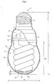
- FIG. 1 is a front view showing the overall construction of the compact self-ballasted fluorescent lamp of the present invention, partially cut away to show its inside.
- This compact self-ballasted fluorescent lamp 1 (hereafter simply, "lamp 1") is a 11W lamp that is an alternative to a 60W incandescent lamp.
- the lamp 1 includes an arc tube 2 that is spirally bent, a ballast circuit 3 for lighting the arc tube 2, a case 4 that contains the ballast circuit 3 and has a base 5, and a globe 6 that covers the arc tube 2.
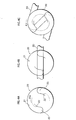
- FIG. 2A is a front view showing the construction of the arc tube 2, partially cut away to show its inside.
- FIG. 2B is a bottom view of the arc tube 2 as viewed from below.
- the arc tube 2 is positioned to extend from an opening of the case 4 downward (opposite side to the base 5).
- the glass tube 9 forming the arc tube 2 is turned back at a turning part 10 provided in the substantially middle between its both ends, so that the both ends are positioned at the side where the case 4 is positioned.
- the glass tube 9 has a double-spiral structure that is made up of a first spiral part 11a starting from one end of the glass tube 9 and winding around the axis "A" toward the turning part 10 at the bottom, and a second spiral part 11b starting from the turning part 10 and winding around the axis "A" toward the other end of the glass tube 9.
- the first and second spiral parts 11a and 11b together are wound around the axis "A" by about five winds.
- the state where the glass tube 9 is formed into a double-spiral structure by winding it around the axis "A” is expressed using the number of winds, e. g, "five winds”. It should also be noted here that the glass tube 9 is wound around the axis "A" at a predetermined angle with the horizontal direction (a direction perpendicular to the axis "A") (this angle ⁇ is hereafter referred to as a "spiral angle").
- the spiral structure is chosen for the arc tube 2 due to the following reason.
- the arc tube 2 having the spiral structure can have a longer distance between a pair of electrodes (electrode distance) than a conventional U-shape arc tube.
- the arc tube 2 having the spiral structure can have a longer discharge path than a conventional U-shape arc tube, and accordingly, can be made more compact as a whole.
- Electrodes 7 and 8 are sealed respectively at both ends of the glass tube 9. As these electrodes 7 and 8, coil electrodes made of tungsten are used. These electrodes 7 and 8 are inserted in the glass tube 9 with being temporarily fixed using bead glass. Lead wires 7a, 7b, 8a, and 8b for the electrodes 7 and 8 are bonded to the glass tube 9. In this way, the glass tube 9 is hermetically sealed.
- a rare-earth phosphor is applied to the inner surface of the glass tube 9.
- a phosphor used here is a mixture of three types of phosphors respectively emitting red, green, and blue light, e.g., Y 2 O 3 :Eu, LaPO 4 :Ce, Tb, and BaMg 2 , Al 16 O 27 :Eu and Mn phosphors.
- mercury is enclosed within the glass tube 9 in such a form that can exhibit, at the time of lighting operation of the arc tube 2, mercury vapor pressure characteristics being substantially the same as mercury vapor pressure characteristics exhibited by mercury enclosed within the glass tube 9 in the single form.
- mercury enclosed may be in the single form, or may be in another form, such as the form of an alloy containing zinc, as long as it can exhibit at the time of lighting operation mercury vapor pressure characteristics being substantially the same as mercury vapor pressure characteristics exhibited by mercury in the single form.
- a mercury vapor pressure of an alloy is a vapor pressure exhibited by mercury vaporized when the lamp is lit.
- the arc tube 2 is held by the holder 12 by fixing its one end at the side of the electrodes 7 and 8 to the bottom surface of the holder 12. As shown in FIG. 1 , electric components 13 for lighting the arc tube 2 are attached to the back side of the holder 12. These electric components 13 constitute the ballast circuit 3 for lighting the arc tube 2.
- the case 4 is made of a synthetic resin and is in a tubular shape having a larger diameter as closer to its bottom end as shown in FIG. 1 .
- the holder 12 is placed in the opening of the case 4 so that the side of the holder 12 where the ballast circuit 3 is provided is positioned back within the case 4.
- a peripheral part of the holder 12 is fixed to the inner wall of the case 4 via an appropriate fixing means such as an adhesive and a screw.
- the E26 type base 5 is attached to the top end of the case 4, which is the opposite side to the opening of the case 4. It should be noted here that electrical coupling between the arc tube 2 and the ballast circuit 3, and electrical coupling between the base 5 and the ballast circuit 3 are not shown in FIG. 1 .
- the globe 6 is provided to cover the arc tube 2.
- An opening of the globe 6 is placed inside the opening of the case 4, and an end of the globe 6 at the opening side is fixed to the inner wall of the case 4 at its opening via an appropriate fixing means such as an adhesive and a screw.
- the globe 6 and the case 4 constitute an envelope.
- an outer diameter of the lamp 1, i.e., an outer diameter of the globe 6, is assumed to be the lamp diameter " ⁇ "
- a total length of the lamp 1, i.e., a total length of the envelope including the base 5 of the case 4 is assumed to be the lamp length "L".
- the globe 6 in the present embodiment is made of glass, and is in the "A" shape.
- a bottom end part of the globe 6 at its inner wall and a bottom end part (at the side of the turning part 10) of the arc tube 2 are thermally connected with each other via a heat-conductive member 15.
- a mercury vapor pressure in the arc tube 2 can be effectively decreased by lowering the temperature of the coolest part of the arc tube 2.
- a part of the arc tube 2 that is the most distant from the electrodes 7 and 8, i.e., the bottom end part of the arc tube 2 is the coolest part of the arc tube 2. It should be noted here that this coolest part of the arc tube 2 corresponds to the turning part 10 of the glass tube 9.
- the heat-conductive member 15 examples include metal, synthetic resin, and rubber.
- the heat-conductive member 15 has high light transmissivity, considering that light emitted from the arc tube 2 is discharged, via the heat-conductive member 15, from the globe 6 to outside, particularly in the downward direction. Further considering an increase in the temperature of the arc tube 2, it is preferable that the heat-conductive member 15 has high heat resistance.
- a specific material chosen by considering these factors is a transparent silicone resin.
- the glass tube 9 forming the arc tube 2 has the tube inner diameter " ⁇ i” of 7.4mm and the tube outer diameter " ⁇ o" of 9.0mm.
- the electrode distance is 340mm.
- the arc tube 2 is formed to have a spiral structure in which the glass tube 2 is wound around the axis "A” by about five winds.
- the arc tube 2 has the outer diameter " ⁇ h” of 36mm, and the length "Lh” of 64mm.
- a distance "S" between the turning part 10 of the glass tube 9 and each of the first spiral part 11a and the second spiral part 11b that are turned back at the turning part 10 and are positioned at the bottom is 4. 5mm, which is a value calculated using the tube outer diameter " ⁇ o" of the glass tube 9 being 9.0mm. Therefore, a ratio of (a) non light-emitting areas (gaps formed between the turning part 10 and each of the first and second spiral parts 11a and 11b) to (b) light emitting areas (the spiral parts 11a and 11b, and the turning part 10) shown in the bottom view of the arc tube 2 is small. Accordingly, substantially uniform luminous distribution can be obtained, and further, vertical illuminance, which is illuminance from the bottom end part of the arc tube 2 in the vertical direction, can be enhanced.
- the globe 6 has the outer diameter " ⁇ " of 55mm and the length "Lb” of 58mm.
- the globe 6 is provided to cover the arc tube 2.
- the length “Lh” of the arc tube 2 (64mm) is longer than the length "Lb” of the globe 6 (58mm) (see FIG. 1 ) because the holder 12 holding the arc tube 2 is attached to the case 4 as being partially inserted in the case 4.
- the lamp 1 has the lamp diameter " ⁇ " of 55mm and the lamp length "L” of 110mm. Comparing with a 60W incandescent lamp for general lighting having the lamp diameter of 60mm and the lamp length of 110mm, the lamp 1 has the lamp diameter being 5mm smaller and the lamp length being equivalent. This means that the lamp 1 is more compact than the 60W incandescent lamp.
- the lamp 1 was lit with the base 5 being oriented upward by applying the input power of 11W. According to the measurement results for the lamp 1, the luminous flux rising characteristics at the lamp startup were equivalent to those of a conventional fluorescent lamp for general lighting. Also, at the lamp current of about 75mA, the luminous flux was 790lm, and the luminous efficiency was 71.9lm/W, which is higher than the targeted luminous efficiency of 70lm/W. Further, the lamp life of 6000 hours or more was confirmed.
- FIGS. 3A to 3C and FIGS. 4A to 4C are drawings for explaining the process of manufacturing a double-spiral arc tube using a mandrel.
- FIGS. 3A to 3C are front views of the mandrel.
- FIGS. 4A to 4C are top views of the mandrel.
- a mandrel 20 is set ready as shown in FIGS. 3A and 4A .
- the mandrel 20 is in a cylindrical shape and has a groove 25 at its outer surface.
- the groove 25 is in a double-spiral shape extending from a top of the mandrel 20 toward a bottom of the mandrel 20 (a bottom end part of the mandrel 20).
- two turn-forming parts 22 for forming the turning part 10 of the arc tube 2 are symmetrically provided with respect to the center of the top 21 of the mandrel 20 (a point on the axis of the mandrel 20) (see FIG. 4A ).
- a reference numeral 25a in FIGS. 3A and 4A indicates a bottom surface of the groove 25 (to be an inner circumference of a spiral arc tube).
- the turn-forming parts 22 are positioned at one end of the bottom surface 25a at the side of the top 21 in the spiral direction.
- an attaching part 24 is provided for attaching the mandrel 20 to a driving device.
- the driving device has the function of moving the mandrel 20 in the axis direction while rotating it around the axis.
- the glass tube 30 that is straight and has a circular-shaped cross section is set ready.
- a middle part of the glass tube 30 is heated so as to be softened.
- the softened glass tube 20 is placed in such a manner that its substantially middle part is between the two turn-forming parts 22 at the top 21 of the mandrel 20.
- the mandrel 20 that is holding both ends of the glass tube 30 is moved in direction "X" while being rotated around the axis in direction "A". This results in the softened glass tube 30 being wound around the mandrel 20 along the spiral groove 25.
- a distance by which the mandrel 20 is moved in direction "X" per single rotation is controlled so as to match one pitch of the spiral shape of the groove 25.
- the groove 25 has an arc-shaped cross section, for the purpose of enabling the glass tube 30 that has been wound up to have a circular-shaped cross section.
- a gas such as nitrogen whose pressure is controlled is being blown into the glass tube 30.
- a gas may be blown into the glass tube 30 after the glass tube 30 is wound around the mandrel 20 along the groove 25.
- a liquid such as water and butyl acetate, may be injected into the glass tube 30.
- the mandrel 20 When the winding of the glass tube 30 is completed and the glass tube 30 is cooled down, the mandrel 20 is rotated in the direction opposite to the winding direction (the direction opposite to direction "A"), so that the glass tube 30 can be detached from the mandrel 20.
- the mandrel 20 By rotating the mandrel 20 in the direction opposite to direction "A" shown in FIG. 3 , the glass tube 30 can be easily detached from the mandrel 20.
- the inventors examined various methods for suppressing degradation of the luminous efficiency during lighting of the lamp in which mercury is enclosed within the arc tube 2 not in the form of an amalgam but in the single form.
- the luminous efficiency is said to be degraded during lighting due to the following reason.
- a mercury vapor pressure within the arc tube increases as the temperature of the arc tube increases. Accordingly, the number of mercury atoms present in a discharge space increases, and ultraviolet light emitted from one mercury atom is absorbed by another mercury atom. As a result, the luminous efficiency is degraded.
- the inventors first thought of shortening an optical path on which ultraviolet light emitted frommercury atoms travels to the tube wall (inner circumference) of the arc tube. By doing so, the inventors thought that an amount of ultraviolet light absorbed by mercury atoms could be reduced. In other words, by shortening the tube inner diameter " ⁇ i" of the glass tube 9 forming the arc tube 2, the inventors thought that the degradation of the luminous efficiency could be suppressed.
- the inventors carried out experiments for determining a mercury vapor pressure that can achieve the maximum luminous efficiency at each of various values for the tube inner diameter " ⁇ i" of the glass tube 9 ranging from 5 to 12mm.
- the inventors manufactured lamps each varying in the tube inner diameter " ⁇ i” by 1mm from 5 to 12mm, and carried out the experiments using these lamps.
- values ranging from 5 to 12mm were chosen for the tube inner diameter " ⁇ i” due to the following reason.
- the tube inner diameter " ⁇ i" is 5mm or less, placing the electrodes 7 and 8 in the arc tube 2 is difficult.
- the tube inner diameter " ⁇ i" is 12mm or more, the arc tube 2 becomes large in size, thereby failing to make the lamp 1 compact.
- the electrode distance "Le” corresponding to the tube inner diameter " ⁇ i” is determined at such a value that enables the tube wall load "we” of the arc tube 2 to be 0.16W/cm 2 , using data collected using conventional lamps.
- the inner-electrode distance "Le” is determined at such a value because the inventors' examination results relating to the lamp life characteristics ensure that the lamp life of about 6000 hours can be achieved for the lamp 1 when the tube wall load "we” is 0.16W/cm 2 .
- the tube wall load "we” can be obtained by dividing the arc tube input by the surface area " ⁇ ⁇ ⁇ i ⁇ Le" of the inner circumference of the arc tube 2.
- the arc tube input is calculated by multiplying the input power (11W) and the circuit efficiency (0.91) of the ballast circuit 3.
- the maximum luminous-flux temperature "T” increases as the tube inner diameter " ⁇ i"' decreases.
- the maximum luminous-flux temperature "T” is as high as 65°C.
- the coolest-point temperature i.e., the temperature of the bottom part of the arc tube 2
- the maximum luminous-flux temperature is substantially the same as the maximum luminous-flux temperature
- the coolest-point temperature and the maximum luminous-flux temperature are compared because the maximum luminous-flux temperature is such a temperature that corresponds to a mercury vapor pressure at which the arc tube 2 achieves the maximum luminous flux (optimum mercury vapor pressure), and also a mercury vapor pressure in the arc tube 2 depends on the coolest-point temperature of the arc tube 2.
- the inventors examined various methods for lowering the coolest-point temperature of the arc tube 2 during lighting. As long as such a method is available for lowering the coolest-point temperature of the arc tube 2 during lighting to 65°C or lower, degradation of the luminous efficiency during lighting can be suppressed simply by reducing the tube inner diameter " ⁇ i" of the arc tube 2.
- the inventors manufactured the lamp 1 including the arc tube 2 formed by the glass tube 9 with the tube inner diameter " ⁇ i" of 7.4mm, the tube outer diameter " ⁇ o” of 9.0mm, and the electrode distance "Le” of 340mm.
- the lamp 1 has substantially the same dimensions as a 60W incandescent lamp (with the lamp diameter " ⁇ " of 60mm and the lamp length "L” of 110mm). Then, the lamp 1 was lit by applying the input power of 11W. The temperature of the arc tube 2 and the globe 6 was measured. Is should be noted here that the lamp 1 was lit with the base being oriented upward. It should also be noted here that the globe 6 was of an A-type that is the same as for the 60W incandescent lamp.
- the temperature of the bottom end part was about 75°C, which was the coolest in the arc tube 2. That is to say, the coolest point was formed in the bottom end part of the arc tube 2.
- the experimental results indicate the following. If the coolest-point temperature of the arc tube 2 can be lowered by 10°C or more, the coolest-point temperature of the arc tube 2 during lighting and the maximum luminous-flux temperature "T" that can achieve the maximum luminous flux can be made substantially the same.
- the temperature of the bottom end part of the globe 6 opposing to the coolest point of the arc tube 2 was about 50°C.
- a temperature difference between the bottom end part of the arc tube 2 and the bottom end part of the globe 6 was about 25°C.
- the inventors thought that the temperature of the arc tube 2 could be lowered by conducting heat in the arc tube 2 during lighting to the globe 6 covering the arc tube 2.
- the inventors chose the method of thermally connecting the coolest point 16 of the arc tube 2 to the globe 6 opposing to the coolest point 16 via a heat-conductive member as shown in FIG. 1 , and examined such effective ways.
- the inventors tried to find a material that has a high heat resistance and high light transmissivity as describe above, and chose a transparent silicone resin as this material.
- the transparent silicone resin does not spoil the appearance of the lamp 1, nor cause such a problem that the silicone resin appears on the globe 6 as a shade during lighting.
- a distance "d" between the bottom end part of the arc tube 2 and the bottom end part of the globe 6 at its inner wall (see FIG. 1 ) is set at 2mm, and the bottom end part of the arc tube 2 is partially embedded in the silicone resin by about 2mm.
- the inventors found that as to the lamp 1 used for the above measurements, a degree of the coolest-point temperature being lowered could be reduced by setting the distance "d” above 6.0mm. Accordingly, the distance "d” is to be set at 6.0mm or less.
- the arc tube 2 and the globe 6 are both made of glass. If any load, such as impact load, acts on the lamp 1 when the lamp 1 is delivered or when the lamp 1 is loaded into a lighting apparatus or the like, the arc tube 2 and the globe 6 may be damaged. Accordingly, it is preferable that a certain space is provided between the arc tube 2 and the globe 6. The space provided is filled with a silicone resin, and therefore, even if the load acts on the lamp 1 as described above, the load can be absorbed by the silicone resin to a certain degree.
- the lamp 1 with the above-described construction was lit, and the coolest-point temperature at the bottom end part of the arc tube 2 was measured. According to the measurement results, the coolest-point temperature was 63°C, which is about 12°C lower than that for a lamp for which a silicone resin is not used (the coolest-point temperature: 75°C) in the above preliminary examinations.
- the coolest-point temperature at the bottom end part of the arc tube 2 can fall within a range of 60 to 65°C.
- a range of values for the tube inner diameter " ⁇ i" that can achieve the maximum luminous flux of the arc tube 2 is 5.0 to 9.0mm.
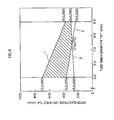
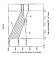
- the inventors examined methods for fulfilling the remaining goals of making the lamp as compact as a 60W incandescent lamp, achieving the luminous efficiency of 70lm/W or more, and achieving the lamp life of 6000 hours or more.
- the examination results are shown in FIG. 6 .
- the lamp 1 that can fulfill the above goals can be obtained by setting the tube inner diameter " ⁇ " and the electrode distance "Le” of the arc tube 2 in a range indicated by a shaded area in FIG. 6 .
- the line “1" in FIG. 6 is a line plotting the maximum electrode distance for each tube inner diameter within a range where the electrodes can be placed in the arc tube 2 in the globe 6 corresponding to the size of a 60W incandescent lamp.
- the electrode distance "Le” is to be set shorter so as to downsize the arc tube 2. Therefore, the maximum length of the arc tube 2 that can be placed in the globe 6 (with the outer diameter " ⁇ " of 55mm and the length "Lb” of 58mm) corresponding to the size of the incandescent lamp is to be calculated first. Then, the maximum electrode distance "Le” for the calculated maximum length of the arc tube 2 can be obtained. It should be noted here that values on the line “1" are maximum values for the electrode distance "Le".
- the line “2" in FIG. 6 is a line plotting the electrode distance "Le” for each tube inner diameter of the lamp that can achieve the lamp life of 6000 hours or more. To ensure the lamp life of 6000 hours ormore, the inventors' examinations relating to the lamp life characteristics reveal that the tube wall load "we" of the arc tube 2 is to be set at 0.16W/cm 2 or less.
- the line “3" in FIG. 6 is a line plotting the electrode distance "Le” for each tube inner diameter of the lamp that can achieve the luminous efficiency of 70lm/W.
- the values for the electrode distance "Le” on the line “3” have been obtained by experiments, and are such values that can achieve the luminous efficiency of 70lm/W.
- the inventors prepared the arc tubes 2 formed by the glass tubes 9 varying in the tube inner diameter from 5.0 to 9.0mm. For the arc tube 2 having each tube inner diameter, the electrode distance "Le” was set at a different value. Lamps employing these prepared arc tubes 2 were lit, and the luminous flux of each lamp was measured. In this way, the electrode distance "Le” that can achieve the luminous efficiency of 70lm/W was obtained.
- the construction of the lamp 1 according to the present embodiment can be concluded as follows.
- mercury is enclosed not in the form of an amalgam but in the single form.
- the tube inner diameter " ⁇ i" of the glass tube 9 forming the arc tube 2 is set in a range of 5.0 to 9.0mm.
- the bottom end part of the arc tube 2 and the bottom end part of the globe 6 at its inner wall is connected via a silicone resin so as to allow heat conduction.
- the luminous flux rising characteristics equivalent to those of the fluorescent lamp for general lighting can be obtained.
- the tube inner diameter " ⁇ i" in a range of 5.0 to 9.0mm, the temperature at which the lamp achieves the maximum luminous flux can be fallen within a range of 60 to 65°C (see FIG. 5 ) . Therefore, even if the temperature of the arc tube 2 increases during lighting, a difference between the temperature of the arc tube 2 and the temperature at which the maximum luminous flux is obtained can be narrowed, thereby enabling degradation of the luminous efficiency to be suppressed. Further, by reducing the tube inner diameter " ⁇ i", the electrode distance "Le” can be lengthened, thereby enabling the luminous efficiency to be improved.
- the lamp 1 can be made as compact as or even more compact than a 60W incandescent lamp, and also can exhibit the luminous efficiency of 70lm/W or more and the lamp life of 6000 hours or more.
- the present invention is applied to a 21W lamp that is an alternative to a 100W incandescent lamp
- the present invention is applied to a 11W lamp that is an alternative to a 60W incandescent lamp.
- components of the lamp according to the present embodiment are given reference numerals 2--.
- the lamp according to the present embodiment is given reference numeral 201. Though being given reference numerals, some components are not shown in the figures (e.g., the lamp 201 and the globe 206).
- a 100W incandescent lamp for general lighting has the lamp diameter " ⁇ " of 60mm and the lamp length "L" of 110mm.
- a conventional 22W lamp that has been an alternative to this 100W incandescent lamp has the lamp diameter " ⁇ " of 65mm and the lamp length "L” of 140mm. This means that the conventional 22W lamp has the lamp diameter " ⁇ " about 5mm larger and the lamp length "L” about 30mm longer than the 100W incandescent lamp. It should be noted here that the conventional 22W lamp has the luminous flux of 1520lm and the luminous efficiency of 69.1lm/W.
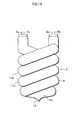
- FIG. 7 is a front view showing the overall construction of an arc tube 202 according to the present embodiment.
- the lamp 201 according to the present embodiment has the same basic construction as the lamp 1 according to the first embodiment, with the only difference being in the following point.
- the input power for the lamp 201 is 21W, which is larger than the input power 11W for the lamp 1.
- the electrode distance in the arc tube 202 of the lamp 201 is set longer than that in the lamp 1.
- the arc tube 201 has a spiral structure including about seven winds as shown in FIG. 7 , whereas for the lamp 1 the spiral structure includes about five winds.
- tube inner diameter " ⁇ i" of a glass tube 209 is set in a range of 5.0 to 9.0mm inclusive, for the same reasons as stated in the first embodiment.
- the arc tube 202 is formed by the glass tube 209 having the tube inner diameter " ⁇ i” of 7.4mm and the tube outer diameter " ⁇ o” of 9.0mm, and the electrode distance "Le” is set at 640mm.
- the glass tube 209 is formed to have a spiral structure including about 7 winds.
- the arc tube 202 has the outer diameter " ⁇ h” of 36mm and the length "Lh” of 85mm.
- the globe 206 has the outer diameter " ⁇ " of 60mm and the length "Lb” of 80mm.
- the lamp diameter " ⁇ " is 60mm and the lamp length “L” is 128mm, meaning that the lamp 201 is more compact than the conventional 22W lamp (with the lamp diameter " ⁇ " of 65mm and the lamp length “L” of 140mm).
- the lamp 201 has the lamp diameter " ⁇ ” being 5mm smaller and the lamp length "L” being 12mm shorter than the conventional 22W lamp.
- the lamp 201 was lit with the base being oriented upward by applying the input power of 21W. According to the measurement results for the lamp 201, the luminous flux rising characteristics at the lamp startup were equivalent to those of a conventional fluorescent lamp for general lighting. Also, at the lamp current of about 100mA, the luminous flux was 1520lm, and the luminous efficiency was 72.4lm/W, which is higher than the targeted luminous efficiency of 70lm/W. Further, the lamp life of 6000 hours or more was confirmed.
- the dimensions of the lamp 201 are set in the following way, for the purpose of achieving the goal of making the lamp 201 more compact than the conventional 22W lamp.
- the lamp diameter " ⁇ " is set in a range of 60 to 65mm, which is smaller than the lamp diameter " ⁇ " of 65mm of the conventional 22W lamp.
- the lamp length "L” is set in a range of 120 to 135mm, which is shorter than the lamp length "L” of 140mm of the conventional 22W lamp.
- the goal is set to achieve the target luminous efficiency of 70lm/W for the lamp 201, which is not less than that of the conventional 22W lamp (69lm/W). Also, as in the first embodiment, the goal is set to achieve the lamp life of 6000 hours or more for the lamp 201.
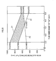
- the inventors prepared a number of lamps 201 each varying in the tube inner diameter " ⁇ " of the glass tube 209 and the electrode distance "Le” in the arc tube 202, and carried out measurements of these lamps, to find out values that can satisfy the above goals of making the lamp more compact, improving the luminous efficiency, and ensuring the lamp life.
- the measurement results are shown in FIG. 8 .
- the lamp 201 that can satisfy the above goals can be obtained.
- the line "21" in FIG. 8 is a line plotting the maximum electrode distance for each tube inner diameter within a range where the electrodes can be placed in the arc tube 202 in the globe 206 corresponding to the size of a 100W incandescent lamp.
- the electrode distance "Le” is obtained by calculations or the like as in the first embodiment. To be more specific, the electrode distance “Le” is obtained using the maximum length of the arc tube 202 that can be placed in the globe 206 (with the outer diameter of 60mm and the length of 80mm) corresponding to the size of the 100W incandescent lamp. It should be noted here that values on the line “21" are maximum values for the electrode distance "Le”.
- the line “22" in FIG. 8 is a line plotting the electrode distance "Le” for each tube inner diameter of the lamp that can achieve the lamp life of 6000 hours or more.
- the tube wall load "we” of the arc tube 202 is to be set at 0.16W/cm 2 or less as in the first embodiment. Using this tube wall load "we", the electrode distance "Le” is calculated.
- the line “23" in FIG. 8 is a line plotting the electrode distance "Le” for each tube inner diameter of the lamp that can achieve the luminous efficiency of 70lm/W. Values for the electrode distance "Le” on this line have been obtained by experiments, and are such values that can achieve the luminous efficiency of 70lm/W as in the first embodiment.
- the present invention is applied to a high-luminous-flux type 23W lamp that is an alternative to a 100W incandescent lamp having the luminous flux of 17001m level, whereas in the second embodiment the present invention is applied to a 21W lamp that is an alternative to a 100W incandescent lamp having the luminous flux of 1500lm level.
- a conventional 22W lamp that has been an alternative to the 100W incandescent lamp is referred to as a "conventional lamp".
- a lamp according to the present embodiment components of the lamp according to the present embodiment are given reference numerals 3--.
- the lamp according to the present embodiment is given reference numeral 301, but these reference numerals are not indicated in the figures.
- the 100W incandescent lamp having the luminous flux of 1700lm level to which the lamp 301 according to the present embodiment aims to be an alternative has the same lamp structure and dimensions as the 100W incandescent lamp having the luminous flux of 1500lm level.
- the 100W incandescent lamp having the luminous flux of 1700lm level has the lamp diameter " ⁇ " of 60mm and the lamp length "L" of 110mm.
- the lamp 301 according to the present embodiment has the same basic construction as the lamp 201 according to the second embodiment, with the only difference being in the following point.
- the input power for the lamp 301 is 23W, which is higher than the input power 21W for the lamp 201.
- the electrode distance in an arc tube 302 of the lamp 301 is set longer than that in the lamp 201.
- the tube inner diameter " ⁇ i" of a glass tube 309 is set in a range of 5.0 to 9.0mm inclusive, for the same reasons as stated in the above embodiments.
- the arc tube 302 is formed by the glass tube 309 having the tube inner diameter " ⁇ i” of 7.4mm and the tube outer diameter " ⁇ o” of 9.0mm, and the electrode distance "Le” is set at 680mm.
- the glass tube 309 is formed to have a spiral structure including about 8 winds.
- the arc tube 309 has the outer diameter " ⁇ h” of 36mm and the length "Lh” of 95mm.
- the globe 306 has the outer diameter " ⁇ " of 60mm and the length "Lb” of 90mm (see FIGS. 1 and 2 ).
- the lamp diameter " ⁇ " is 60mm and the lamp length "L” is 138mm.
- the lamp 301 has the luminous flux improved by 2001m, despite having substantially the same length "L”.
- the lamp 301 has the lamp diameter " ⁇ " being 5mm smaller than the conventional lamp.
- the lamp 301 was lit with the base being oriented upward by applying the input power of 23W. According to the measurement results for the lamp 301, the luminous flux rising characteristics at the lamp startup were equivalent to those of a conventional fluorescent lamp for general lighting. Also, the luminous flux was 1720lm, and the luminous efficiency was 74.8lm/W, which is higher than the target luminous efficiency. Further, the lamp life of 6000 hours or more was confirmed.
- the dimensions of the lamp 301 are set in the following way, for the purpose of achieving the goal of making the lamp 301 more compact than the conventional lamp.
- the lamp diameter " ⁇ " is set in a range of 60 to 65mm, which is smaller than the lamp diameter " ⁇ " of 65mm of the conventional lamp.
- the goals are set for the lamp 301 to achieve the target luminous efficiency of 701m/W or more and the lamp life of 6000 hours or more.
- the inventors prepared a number of lamps 301 each varying in the tube inner diameter " ⁇ i" of the glass tube 309 and the electrode distance "Le” in the arc tube 302, and carried out measurements of these lamps, to find out values that can satisfy the above goals of making the lamp more compact, improving the luminous efficiency, and ensuring the lamp life.
- the measurement results are shown in FIG. 9 .
- the lamp 301 that can satisfy the above goals can be obtained.
- the line “31" in FIG. 9 is a line plotting the maximum electrode distance for each tube inner diameter " ⁇ i” within a range where the lamp diameter " ⁇ " of the lamp 301 at most is substantially equivalent to that of the 100W incandescent lamp and the length "L” of the lamp 301 is substantially equivalent to that of the conventional 22W lamp.
- the electrode distance "Le” for each tube diameter " ⁇ i” is obtained using the maximum length of the arc tube 302 that can be placed in the globe 306 with the outer diameter " ⁇ 5" of about 60mm and the length "Lb” of about 90mm.
- the line “32" in FIG. 9 is a line plotting the electrode distance "Le” for each tube inner diameter of the lamp that can achieve the lamp life of 6000 hours or more. As in the first and second embodiments, values for the electrode distance "Le” are calculated at such values that correspond to the tube wall load "we" of the arc tube 302 being 0.16W/cm 2 .
- the line “33" in FIG. 9 is a line plotting the electrode distance "Le” for each tube inner diameter of the lamp that can achieve the luminous efficiency of 70lm/W. Values for the electrode distance "Le” on this line have been obtained by experiments.
- the present invention is applied to a 7W lamp that is an alternative to a 40W incandescent lamp having the luminous flux of 500lm level, whereas in first embodiment the present invention is applied to a 11W lamp that is an alternative to a 60W incandescent lamp, in the second embodiment the present invention is applied to a 21W lamp that is an alternative to a 100W incandescent lamp, and in the third embodiment the present invention is applied to a 23W lamp that is an alternative to a 100W incandescent lamp.
- a conventional 8W lamp that has been an alternative to the 40W incandescent lamp is referred to as a "conventional lamp".
- components of the lamp according to the present embodiment are given reference numerals 4--.
- the lamp according to the present embodiment is given reference numeral 401, but these reference numerals are not shown in the figures.
- a 40W incandescent lamp to which the lamp 401 according to the present embodiment aims to be an alternative has the lamp diameter " ⁇ " of 55mm, the lamp length "L” of 98mm, and the luminous flux of 4851m. It should be noted here that this 40W incandescent lamp, together with the 60W and 100W incandescent lamps described above, is widely used as a major product in the market. Also, a conventional 8W lamp that has been an alternative to a 40W incandescent lamp has the lamp diameter " ⁇ " of about 60mm and the lamp length "L2" of about 122mm. As for the performances of this conventional 8W lamp, the luminous flux is 500lm and the luminous efficiency is 62.5lm/W.
- the lamp 401 according to the present embodiment has the same basic construction as the lamps according to the first to third embodiments, with the only difference being in the following point.
- the input power for the lamp 401 is 7W, which is smaller than that for the lamps according to the first to third embodiments.
- the electrode distance "Le” in an arc tube 402 of the lamp 401 is set shorter than that in the lamps according to the first to third embodiments.
- the tube inner diameter " ⁇ i" of a glass tube 409 too, is set in a range of 5.0 to 9.0mm inclusive, for the same reasons as stated in the first embodiment.
- the arc tube 402 is formed by the glass tube 409 having the tube inner diameter " ⁇ i” of 7.4mm and the tube outer diameter " ⁇ o” of 9.0mm, and the electrode distance "Le” is set at 250mm.
- the glass tube 409 is formed to have a spiral structure including about 3.5 winds.
- the arc tube 402 has the outer diameter " ⁇ h” of 36mm and the length "Lh” of 52mm.
- the globe 406 has the outer diameter " ⁇ " of 55mm and the length "Lb” of 46mm (see FIGS. 1 and 2 ).
- the lamp diameter " ⁇ " is 55mm and the lamp length “L” is 98mm.
- the lamp 401 is much more compact than the conventional lamp (with the lamp diameter " ⁇ " of 60mm and the lamp length “L” of 122mm), and further, is as compact as the 40W incandescent lamp (with the lamp diameter " ⁇ " of 55mm and the lamp length "L” of 98mm) .
- the lamp 401 was lit with the base being oriented upward by applying the input power of 7W. According to the measurement results for the lamp 401, the luminous flux rising characteristics at the lamp startup were equivalent to those of a conventional fluorescent lamp for general lighting. Also, the luminous flux was 5101m, and the luminous efficiency was 72.91 m/w, achieving the target luminous efficiency. Further, the lamp life of 6000 hours or more was confirmed.
- the dimensions of the lamp 401 are set to achieve the goal of making the lamp 401 substantially as compact as the 40W incandescent lamp.
- the goals are set for the lamp 401 to achieve the target luminous efficiency of at 701m/w and the target lamp life of at 6000 hours or more.
- the inventors prepared a number of lamps 401 each varying in the tube inner diameter " ⁇ " of the glass tube 409 and the electrode distance "Le” in the arc tube 402, and carried out measurements of these lamps, to find out values that can satisfy the above goals of making the lamp more compact, improving the luminous efficiency, and ensuring the lamp life.
- the measurement results are shown in FIG. 10 .
- the lamp 401 that can satisfy the above goals can be obtained.
- the line “41" in FIG. 10 is a line plotting the maximum electrode distance "Le” for each tube inner diameter " ⁇ i” within a range where the lamp 401 have dimensions substantially equivalent to the 40W incandescent lamp.
- the electrode distance "Le” for each tube diameter " ⁇ i” is obtained using the maximum length of the arc tube 402 that can be placed in the globe 406 with the outer diameter of about 55mm and the length "Lb" of about 46mm.
- the line “42" in FIG. 10 is a line plotting the electrode distance "Le” for each tube inner diameter of the lamp that can achieve the lamp life of 6000 hours or more.
- values for the electrode distance "Le” are calculated at such values that correspond to the tube wall load "we" of the arc tube 402 being 0.16w/cm 2 .
- the line “43" in FIG. 10 is a line plotting the electrode distance "Le” for each tube inner diameter of the lamp that can achieve the luminous efficiency of 701 m/W. Values for the electrode distance "Le” on this line have been obtained by experiments.
- a triple U-shape arc tube that is made up of three U-shape glass tubes and a quad U-shape arc tube that is made up of four U-shape glass tubes is described, whereas in the first to fourth embodiments the present invention is applied to the arc tubes 2, 202, 302, and 402 each being formed by a double-spiral glass tube.
- components of the lamp according to the present example are given reference numerals 5--.
- the lamp according to the present example is given reference numeral 501.
- the following describes the basic construction of the lamp 501 including a triple U-shape arc tube or a quad U-shape arc tube.
- mercury is enclosed within the arc tube 502 in the substantially single form.
- the tube inner diameter " ⁇ i" of the glass tube 509 is set in a range of 5.0 to 9.0mm.
- the coolest point 516 of at least one of three U-shape glass tubes 509 constituting the triple U-shape or at least one of four U-shape glass tubes 509 constituting the quad U-shape arc tube and a part of the globe 506 corresponding to the coolest point 516 is thermally connected via a heat-conductive member such as a silicone resin 515.
- the coolest point formed integrally as a part of the connected U-shape glass tube is cooled down.
- FIG. 11A shows the overall construction of the lamp 501 according to the first example, partially cut away to its inside.
- the lamp 501 includes the arc tube 502 for use in a 11W lamp that is an alternative to a 60W incandescent lamp.
- the arc tube 502 is a quad U-shape arc tube that is made up of four U-shape glass tubes.
- FIG. 11B is a plan view showing a cross section of the lamp 501 taken along X-X line in FIG. 11A . It should be noted here that the X-X line in FIG. 11A corresponds to the largest outer diameter of the globe 506.
- the lamp 501 is characterized by including the arc tube 502 in which three or four U-shape glass tubes 509 are bridge-connected to form a single discharge path therein.
- a U-bent part of each glass tube 509 in which the coolest point is formed is thermally connected to a bottom end part of the globe 506 corresponding to the U-bent part via a heat-conductive member such as the silicone resin 515.
- the lamp 501 has the similar construction to the lamp 1 including the double-spiral arc tube 2.
- the tube inner diameter " ⁇ i" of the glass tube 509 and the electrode distance "Le” of the arc tube 501 are particularly set in the range indicated by the shaded area shown in FIG. 6 . Due to this, as in the case of using the double-spiral arc tube 2, the lamp having the luminous efficiency of 70lm/w and the lamp life of 6000 hours can be obtained.
- the arc tube 502 is formed by four U-shape glass tubes 509 each having the tube inner diameter " ⁇ i” of 7.4mm and the tube outer diameter " ⁇ o” of 9.0mm.
- the electrode distance "Le” is set at 340mm.
- the tube width "b" of each U-shape glass tube 509 is 20mm (see FIG. 11B ).
- the arc tube 502 has the maximum outer diameter " ⁇ h” of 46mm and the length "Lh” of 60mm.
- the globe 506 has the outer diameter " ⁇ ” of 60mm and the length "Lb” of 58mm.
- the completed lamp 501 has the lamp diameter " ⁇ " of 60mm and the lamp length "L” of 110mm, as being substantially equivalent to the 60W incandescent lamp.
- the arc tube may be made up of three U-shape glass tubes 509 instead of the four U-shape glass tubes 509.
- the length "Lh” of the arc tube is 73mm, which is longer than the length "Lh” being 60mm of the arc tube 502 including the four U-shape glass tubes 509, and so the length "L” of the arc tube is inevitably as long as 123mm, which is longer than the length "L” 110mm of the arc tube 502 including the four U-shape glass tubes 509.
- the lamp 501 was lit with the base being oriented upward by applying the input power of 11W. According to the measurement results for the lamp 501, the luminous flux rising characteristics at the lamp startup were substantially equivalent to those of a conventional fluorescent lamp for general lighting. Also, the luminous flux was 7801m, and the luminous efficiency was 70.9lm/w. Further, the lamp life of 6000 hours or more was confirmed.
- an arc tube 502a having the same basic construction as the arc tube 502 shown in FIGS. 11A and 11B , i.e., a quad U-shape arc tube is prepared.
- the overall dimensions of the lamp 501a using the quad U-shape arc tube 502a are inevitably larger than that of the lamp using the double-spiral arc tube 202.
- the tube inner diameter " ⁇ i" of the glass tube 509a is set at 7.4mm
- the electrode distance "Le” in the arc tube 502a at 640mm the arc tube 502a has the outer diameter " ⁇ h” of 46mm and the length "Lh” of 95mm
- the globe 506a has the outer diameter " ⁇ " of 65mm and the length "Lb” of 90mm.
- the finished lamp 501a has the lamp diameter " ⁇ " of as large as 65mm and the lamp length "L” of as long as 140mm.
- an arc tube that is made up of five U-shape glass tubes may be used as one method for shortening the increased lamp length "L” of the lamp 506a to 128mm that is the lamp length "L” of the lamp 201 including the double-spiral arc tube 102.
- the target luminous efficiency is 70lm/w or more
- the inventors have examined techniques for further improving the luminous efficiency without changing the size of a lamp.
- components of the lamp according to the present embodiment are given reference numerals 6--.
- the lamp according to the present embodiment is given reference numeral 601.
- FIG. 12 shows the overall construction of a 11W lamp according to the second example, as an alternative to a 60w incandescent lamp.
- the lamp 601 according to the present embodiment has the same basic construction as the lamp 1 according to the first embodiment, with the only difference being in the following point.
- glass tube 609 forming an arc tube 602 has an oval-shaped cross section, whereas in the first embodiment the glass tube 9 has a circular-shaped cross section.
- the glass tube 609 forming the arc tube 602 has the following oval-shaped cross section. Its inner circumference has the minor tube inner diameter (the minor axis of the oval) "D1" of 5.4mm and the major tube inner diameter (the major axis of the oval) "D2" of 7.4mm. Its outer circumference has the minor tube outer diameter of 7.0mm and the major tube outer diameter of 9.0mm. Also, the electrode distance "Le in the arc tube 602 is set at "340+ ⁇ mm".
- a value for " ⁇ ” varies depending on the position of the glass tube 609 that is wound around the axis "A".
- a value for " ⁇ ” varies depending on the distance between the tube center of the glass tube 609 and the axis "A".
- the position of the outermost circumference of the glass tube 609 having an oval-shaped cross section is the same as the position of the outermost circumference of the glass tube 9 having a circular-shaped cross section.
- a value of " ⁇ " for the glass tube 609 is the largest (about 30mm).
- the maj or tube inner diameter "D2" is 7.4mm, which is equal to the tube inner diameter " ⁇ i" in the first and second embodiments.
- the arc tube 602 has a spiral structure including about five winds as in the first embodiment.
- the arc tube 602 has the outer diameter " ⁇ h” of 36mm and the length "Lh” of 64mm.
- the globe 606 has the outer diameter " ⁇ " of 55mm and the length "Lb” of 58mm and can cover the above arc tube 602.
- the lamp 601 has the lamp diameter " ⁇ " of 55mm and the lamp length "L” of 110mm, the lamp diameter being little smaller than the lamp length of the 60W incandescent lamp (with the lamp diameter " ⁇ " of 60mm and the lamp length "L” of 110mm).
- the coolest point 616 formed at the bottom end part of the arc tube 602 and the bottom end part of the globe 606 at its inner circumference are connected via a transparent silicone resin 615.
- the distance "d" between the bottom end part of the arc tube 602 and the bottom end part of the globe 606 at its inner circumference is 2mm.
- the bottom end part of the arc tube 602 is partially embedded by about 2mm in the silicone resin 615.
- the lamp 601 was lit with the base being oriented upward by applying the input power of 11W. According to the measurement results for the lamp 601, the luminous flux rising characteristics at the lamp startup were equivalent to those of a conventional fluorescent lamp for general lightning. Also, at the lamp current of about 70mA, the luminous flux was 820lm, and the luminous efficiency was 74.6lm/W, which is greatly higher the target luminous efficiency of 70lm/W.
- This luminous efficiency shows an improvement of about 4% with respect to the luminous efficiency of the lamp 1 according to the first embodiment.
- the luminous efficiency can be improved even if the arc tube 602 has the same length as the arc tube 2 according to the first embodiment.
- the arc tube 602 having an oval-shaped cross section has a shorter optical path than the arc tube 2 having a circular-shaped cross section. Therefore, the maximum luminous flux temperature for the arc tube 602 having an oval-shaped cross section can be made higher than that for the arc tube 2 having a circular-shaped cross section. Due to this, degradation of the luminous efficiency caused by an increase in a mercury vapor pressure in the arc tube 602 when the arc tube 602 is placed in the globe 606 can be suppressed, and so the luminous efficiency can be improved further. To sum up, it is basically advantageous that the globe-type lamp 601 uses the arc tube 602 having an oval-shaped cross section, in view of improving the luminous efficiency.
- the glass tube 609 forming the arc tube 602 is in the following oval-shaped cross section. Its inner circumference has the minor tube inner diameter "D1" of 5.4mm and the maj or tube inner diameter "D2" of 7.4mm. Its outer circumference has the minor tube outer diameter of 7.0mm and the major tube outer diameter of 9.0mm. Also, the electrode distance "Le” in the arc tube 602 is set at about 365mm.
- the arc tube 602 has a spiral structure including about five winds as in the first embodiment.
- the arc tube 602 has the outer diameter " ⁇ h" of 36mm and the length "Lh” of 64mm.
- the lamp 601 has the lamp diameter " ⁇ " of 55mm and the lamp length "L” of 100mm, and is more compact than the 60W incandescent lamp (with the lamp diameter " ⁇ " of 60mm and the lamp length "L” of 110mm).
- the lamp 601 was lit with the base being oriented upward by applying the input power of 11W. According to the measurement results for the lamp 601, the luminous flux rising characteristics at the lamp startup were equivalent to those of a conventional fluorescent lamp for general lighting. Also, at the lamp current of about 65mA, the luminous flux was 810lm, and the luminous efficiency was 74.6lm/W.
- the lamp 1 according to the first embodiment includes the arc tube 2 formed by the glass tube 9 with a circular-shaped cross section having the inner diameter of 7.4mm and the outer diameter of 9.0mum and the electrode distance is set at 340mm.
- the lamp 1 according to the first embodiment was lit with the base being oriented upward at the lamp current of 75mA. According to the measurement results, the luminous flux was 7901m and the luminous efficiency was 71.9lm/W.
- the input current can be reduced by about 10mA
- the luminous flux can be increased by 20lm
- the luminous efficiency can be increased by 2.7lm/W, as compared with the case of the first embodiment where a glass tube (9) having a circular-shaped cross section with the tube inner diameter being equal to the major tube inner diameter of the above oval-shaped cross section is used.
- the following describes a manufacturing method for the arc tube 602 formed by the glass tube 609 having an oval-shaped cross section.
- the arc tube 602 having the oval-shaped cross section according to the present example is manufactured using a glass tube 630 (not shown) that is straight and has a circular-shaped cross section as the glass tube 9 used for the arc tube 2 in above embodiments.
- the arc tube 602 is also manufactured by the process of softening the middle part of the glass tube 630 using a heating furnace, and spirally winding the softened glass tube 630 around a mandrel 620.
- the manufacturing method for the arc tube 602 formed by the glass tube 609 having an oval-shaped cross section in the present embodiment differs from the manufacturing method for the arc tube 2 formed by the glass tube 9 having a circular-shaped cross section described in the first embodiment in the following point.
- the pressure of a gas, such as nitrogen, to be blown into the glass tube 631 in the forming process is adjusted to be reduced, in such a manner that the cross section of the glass tube 631 is made into an oval-shape.
- the groove 625 of the mandrel 620 has an oval arc-shaped cross section.
- a shape that matches the cross section of the groove 625 is an oval-shape having the major axis in the direction substantially parallel to the axis direction of the mandrel 620, e.g., the direction inclined to the axis direction at the spiral angle.
- the glass tube 631 being softened as described above is pressed against the mandrel 620 by a gas blown into the glass tube 631 during the forming process, so that the arc tube 602 having an oval-shaped cross section can be easily obtained.
- both ends of the shaped glass tube 631 retain circular-shaped cross sections of the unshaped glass tube. Even if the minor tube inner diameter "D1" is 5.0mm or less, therefore, the major tube inner diameter "D2" at both the ends is 5.0mm or more. Therefore, the electrodes can be placed.
- the inventors first examined the method of reducing the inner diameter of the glass tube 9, for the purpose of increasing the maximum luminous-flux temperature.
- the electrodes 7 and 8 cannot be placed in the glass tube 9 if the tube inner diameter " ⁇ i" is set smaller than 5mm.
- the electrodes can be placed by utilizing the major tube inner diameter "D2" even if the minor inner diameter "D1" is 5mm or less.
- the electrode distance (the shortest distance between the electrodes) can be longer, as compared with a glass tube having a circular-shaped cross section whose diameter is equal to the maj or tube inner diameter "D2" of this oval shape.
- FIG. 14 shows the glass tube 609 cut away along a plane including a predetermined position thereof and a position distant from the predetermined position by a half wind.
- the oval-shape having the minor tube inner diameter "D1" in direction "B” is indicated by a solid line, and a circle having the tube inner diameter being equal to the major tube inner diameter "D2" of the oval-shape is indicated by a thin line (corresponding to the arc tube 2 in the first embodiment). It should be noted here that the figure indicates the case where the glass tubes 9 and 609 have cross sections sharing the same center.
- the electrode distance in each of the arc tubes 2 and 602 is typically the shortest distance connecting a pair of electrodes provided therein.
- the shortest spiral path corresponds to an inner circumference of the glass tube 609 positioned closest to the axis "A", i.e., a circumference with the diameter being "L1" .
- the shortest spiral path corresponds to an inner circumference of the glass tube 9 closest to the axis "A", i.e., a circumference with the diameter of being "L2".
- the arc tube 602 having the oval-shaped cross section has a longer electrode distance than the arc tube 2 having the circular-shaped cross section.
- the arc tubes 2 and 602 are formed by winding the glass tubes 9 and 609 around the axis "A" by a plurality of winds, a difference in the electrode distance between the arc tubes 2 and 602 would be remarkable for the total length of the arc tubes 2 and 602. Therefore, the luminous efficiency can be improved further.
- the outer circumference is closer to the axis "A" than the outer circumference if the glass tube 9 having a circular-shaped cross section. Therefore, the outer circumference of the arc tube 602 can be made smaller than that of the arc tube 2.
- the cross section of the glass tube 609 in an oval-shape having the minor tube inner diameter "D1" in direction "B"
- an optical path on which ultraviolet light emitted form mercury atoms travels to the tube wall can be shortened, as compared with the case of the arc tube formed by a glass tube 2 having a circular-shaped cross section with the diameter being equal to the major tube inner diameter of the oval shape.
- the electrode distance can also be lengthened. Therefore, the luminous efficiency can be improved further.
- the inventors prepared a number of lamps including arc tubes 602 formed by the glass tubes 609 having an oval-shaped cross section, each varying in a ratio of the minor tube inner diameter "D1" to the major tube inner diameter "D2" of the oval-shape, and measured the luminous efficiency of each of the prepared lamps.
- the measurement results are shown in FIG. 15 as the relationship between the ratio "D1/D2” and an improvement ratio of luminous efficiency. According to these experimental results, the improvement ratio of luminous efficiency increases as the ratio D1/D2 decreases.
- the electrode distance was uniformly set at 400mm and the major tube inner diameter "D2" was also uniformly set at 8.0mm.
- the minor tube inner diameter "D1" was variously set at 7.4mm, 6.7mm, 6.1mm, 5.3mm, 4.5mm, and 3.6mm. Each lamp was lit with the base being oriented upward at the lamp current of 90mA.
- the luminous efficiency is improved by 2% or more as compared with when the glass tube has the circular-shaped cross section with the tube inner diameter being equal to the major tube inner diameter "D2". It should be noted here that a 2% improvement of the luminous efficiency can make the consumers notice improved luminous flux and so can add values to products.
- the inner circumference of the glass tube 609 forming the arc tube 602 is in a range of 5 to 9mm inclusive for the same reason as that for the tube inner diameter " ⁇ i" of the glass tube 9 being set in a range of 5 to 9mm inclusive in the first embodiment.
- the minor tube inner diameter "D1" is not less than 3mm but is less than the major tube inner diameter "D2".
- the minor tube inner diameter "D1” is be set at a value not less than 3mm so that the electrodes can be easily placed.
- the minor tube inner diameter "D1” is to be set at a value less than the major tube inner diameter "D2", for the purpose of making the inner circumference of the cross section substantially in an oval-shape.
- the electrodes are each in a flat shape as shown in FIG. 2 . A space of about 5mm x 3mm on a plane is required for these electrodes.
- the inner diameter of the straight glass tube 630 used for forming the spiral arc tube 602 is to be determined first. Then, the electrode distance "Le” of the arc tube 602 can be determined in the range indicated by the shaded area in FIG. 6 for the arc tube 2 having the circular-shaped cross section described in the first embodiment. To be more specific, the electrode distance "Le” can be determined using a value calculated by assuming the minor tube inner diameter "D1" as the tube inner diameter " ⁇ i" of the arc tube 2 shown in the figure.
- FIG. 6 only shows values for the electrode distance "Le” when the tube inner diameter " ⁇ i” is 5mm or less.
- the maximum values for the electrode distance "Le” when the tube inner diameter " ⁇ i” is not less than 3mm and is less than 5mm are on or below a line plotting points (3.0, 1160) and (5.0, 690), showing the tube inner diameter " ⁇ i” and the electrode distance "Le” as rectangular coordinates ( ⁇ i, Le).
- the minimum values for the electrode distance "Le” are on or above a line drawn as extended from the line “2" until when the tube inner diameter " ⁇ i” is 3.0mm.
- values for ( ⁇ i, Le) are to be set in a range surrounded by points (3.0, 445), (7.4, 275), (9.0, 290), (9.0, 360), and (3.0, 1160).
- both ends of the glass tube i.e., one end of the arc tube at the side where the case is positioned, are formed so as to extend straight in the direction substantially parallel to the axis "A" of the spiral arc tube (the direction perpendicular to a main surface of the holder) .
- the ends of the glass tube may instead be inclined so that parts thereof closer to the holder are closer to the axis "A".
- the lamp 601 according to the second example is an example where the present invention is applied to the arc tube formed by the glass tube having an oval-shaped cross section for use in a 11W lamp as an alternative to a 60W incandescent lamp.
- the present example can be applied to arc tubes for use in lamps with other input powers.
- the dimensions of the arc tube 602a are to be set with reference to FIG. 8 in the same manner as described above.
- the minor tube inner diameter "D1" of the glass tube 609a used for forming the arc tube 602a is set first, so that the electrode distance "Le” can be determined using a value of the minor tube inner diameter "D1".
- FIG. 8 does not show values for the electrode distance "Le” when the tube inner diameter " ⁇ i” is 5mm and less.
- the maximum values for the electrode distance "Le” when the tube inner diameter " ⁇ i” is not less than 3mm and is less than 5mm are on or below a line drawn as extended from the line "21" until when the tube inner diameter " ⁇ i” is 3.0mm.
- the minimum values for the electrode distance "Le” are on or above a line drawn as extended from the line “22" until when the tube inner diameter " ⁇ i" is 3.0mm.
- values for ( ⁇ i, Le) are to be set in a range surrounded by points (3.0, 840), (7.4, 530), (9.0, 560), (9.0, 620), and (3.0, 1085).
- the dimensions of the arc tube 602b are to be set with reference to FIG. 9 in the same manner as described above.
- the minor tube inner diameter "D1" of the glass tube 609b used for forming the arc tube 602b is set first, so that the electrode distance "Le” can be determined using a value of the minor tube inner diameter "D1".
- FIG. 9 does not show values for the electrode distance "Le” when the tube inner diameter " ⁇ i” is 5mm and less.
- the maximum values for the electrode distance "Le” when the tube inner diameter " ⁇ i” is no less than 3mm and is less than 5mm are on or below a line drawn as extended from the line “31” until when the tube inner diameter " ⁇ i” is 3.0mm.
- the minimum values for the electrode distance "Le” are on or above a line drawn as extended from the line "32” until when the tube inner diameter " ⁇ i” is 3.0mm.
- values for ( ⁇ i, Le) are to be set in a range surrounded by points (3.0, 975), (7.4, 570), (9.0, 600), (9.0, 670), and (3.0, 1165).
- the dimensions of the arc tube 602c are to be set with reference to FIG. 10 in the same manner as described above.
- the minor tube inner diameter "D1" of the glass tube 609c used for forming the arc tube 602c is set first, so that the electrode distance "Le” can be determined using a value of the minor tube inner diameter "D1".
- FIG. 10 does not show values for the electrode distance "Le” when the tube inner diameter " ⁇ i” is 5mm and less.
- the maximum values for the electrode distance "Le” when the tube inner diameter " ⁇ i” is no less than 3mm and is less than 5mm are on or below a line drawn as extended from the line "41" until when the tube inner diameter " ⁇ i” is 3.0mm.
- the minimum values for the electrode distance "Le” are on or above a line drawn as extended from the line "42” until when the tube inner diameter " ⁇ i” is 3.0mm.
- values for ( ⁇ i, Le) are to be set in a range surrounded by points (3.0, 330), (7.4, 200), (9.0, 230), (9.0, 320), and (3.0, 725).
- the first to fourth embodiments describe the case where the arc tube has a spiral structure where the glass tube is spirally wound and has an outer circumference being in a circular shape as viewed in the axis direction
- the glass tube may be wound in such a manner that the outer circumference of the arc tube viewed in the axis direction is in an oval-shape.
- a split molding fixture or the like needs to be used.
- the above embodiments describe the case where the spiral arc tube has the axis being in the same direction as the central axis of the base (vertical direction), the axis of the spiral arc tube may be in the direction perpendicular to the central axis of the base.
- the second example describes the case where the inner circumference surface of the cross section of the glass tube is not in a circular shape, in particular, it is in an oval-shape having the first diameter in the direction substantially perpendicular to the axis around which the glass tube is wound being smaller than the second diameter in the direction substantially parallel to the axis.
- the inner circumference surface of the cross section of the glass tube may be in any other shapes as long as the first diameter is smaller than the second diameter and a ratio of the first diameter to the second diameter is 0.85 or less.
- the cross section of the glass tube 909 may be in such an oval-shape as shown in FIG. 16A where the inner side and the outer side of the cross section of the arc'tube 902 have a different shape.
- the inner circumference part of the arc tube 902 at the side of the axis with respect to the major diameter "D2" (hereafter referred to as "an inner side of the arc tube", i.e, right side in FIG. 16 ) has such an oval shape with its minor diameter being twice the radius "D11".
- the inner circumference part of the arc tube 902 positioned at the opposite side hereafter referred to as "an outer side of the arc tube", i.e., left side in FIG. 16 ) has such an oval shape with its minor diameter being twice the radius "D12".
- the inner circumference part of the arc tube 902 at the outer side may have such a circular shape with the diameter being equal to the major diameter "D2".
- the inner circumference part of the arc tube 902 at the inner side is more distant from the axis of the arc tube 902, and so the electrode distance can be longer, as compared with the case where the cross section of the glass tube 909 has an oval shape with the minor diameter being twice the radius "D12".
- the cross section of the glass tube 931 can be easily made into the above-described shape.
- the inner circumference part of the arc tube 902 at the inner side with respect to the major diameter "D2" may be projected in a triangular shape toward the inner side of the arc tube 902. Further, the inner circumference part of the arc tube 902 at the outer side with respect to the major diameter "D2” may have a circular shape with the diameter being equal to the major diameter "D2".
- FIGS. 16A and 16B show the cross section of the glass tube 909 in which the inner circumference part at the outer side of the arc tube 909 is in an oval-shape.
- the substantially oval-shape of the present example intends to include such an oval-shape.
- the inner circumference part of the arc tube 902 at the inner side may be in a V-shape that is recessed toward the outer side of the arc tube 902. Further, the inner circumference part of the arc tube 902 at the outer side may be in a circular shape with the diameter being equal to the major diameter "D2".
- the glass tube 909 used for forming the arc tube 902 has a cross section being in a V-shape, with the minor tube diameter "D1" (the length of the shorter side shown in the figure) of 4.0mm and the major tube diameter "D2" (the length of the longer side shown in the figure) of 7.4mm.
- the electrode distance is set at 380mm.
- the arc tube 902 is formed to have a spiral structure having five winds, and has the outer diameter " ⁇ h" of 36mm and the length "Lh” of 60mm as in the fifth embodiment.
- the lamp has the lamp diameter " ⁇ " of 55mm and the lamp length "L” of 100mm, and is more compact than a 60W incandescent lamp (with the lamp diameter " ⁇ " of 60mm and the lamp length "L” of 110mm).
- the lamp was lit with the base being oriented upward by applying the input power of 11W. According to the measurement results for the lamp, the luminous flux rising characteristics at the lamp startup were equivalent to those of a conventional fluorescent lamp for general lighting. Also, at the lamp current of about 71mA, the luminous flux was 830lm; and the luminous efficiency was as high as 75.5lm/W.
- the luminous efficiency shows an improvement of 2.6% compared with the lamp in which the glass tube has an oval-shaped cross section as described in the item 1. b) in the sixth embodiment. It should be noted here that this lamp has the lamp life of 6000 hours or more as the lamps according to the above embodiments. In this case, too, by making the cross section of the groove 925 in a V-shape as shown in FIG. 17C , the cross section of the glass tube 931 can be easily made into a V-shape.
- the direction of the first diameter "D1" of the cross section corresponds to the direction inclined at the spiral angle with respect to the horizontal direction (the axis direction).
- the present invention assumes this case to be included in the direction substantially perpendicular to the axis.
- the shape of the inner circumference and the shape of the outer circumference of each of the glass tubes 609 and 909 are substantially the same, they may not necessarily be the same.
- the inner circumference may be in an oval-shape, and the outer circumference may be in a circular shape.
- mercury is enclosed within an arc tube basically not in the form of an amalgam but in the single form.
- a small-sized auxiliary amalgam according to a conventional technique, e.g., a stainless mesh plated with indium (In), may be provided in a vicinity of the electrodes or the like.
- a small-sized auxiliary amalgam only absorbs a small portion of mercury enclosed, leaving a required amount of mercury present in the single form within the arc tube, and so does not degrade the luminous efficiency rising characteristics.
- an amalgam used here is mainly composed of In and/or Pb, more specifically, is BiIn, BiPbSn, InPb, BiIn, InPbSn, or the like.
- mercury may be enclosed in the form of an amalgam if the amalgam has mercury vapor pressure characteristics substantially equal to those of mercury in the single form.
- Such an amalgam having substantially equivalent mercury vapor pressure characteristics is an amalgam not mainly composed of In and/or Pb, specifically, ZnHg, FeHg, BiHg, BiSnHg, SnHg, and the like. A single or a combination of such amalgams may be used.
- the other methods may be employed as long as the heat in the arc tube can be conducted to the globe side during lighting, i.e., as long as the bottom end part of the arc tube and the bottom end part of the globe at its inner wall are thermally connected during lighting.
- the bottom end part of the arc tube and the silicone resin may not be connected with each other but may simply be contacted with each other.
- the silicone resin and the arc tube may not be contacted with each other when the lamp is off, and the silicone resin may be expanded to be contacted with the arc tube after the lamp is lit.
- a degree of the temperature decrease in the arc tube is lower than when the silicone resin and the arc tube, or the silicone resin and the globe, are connected with each other. Because the silicone resin and the arc tube, or the silicone resin and the globe, are contacted with each other after the lamp is lit, at least a certain degree of effect of lowering the temperature of the arc tube can be obtained.
- an amount of heat conducted to the heat-conductive member is to be increased.
- a swelling unit is provided for increasing an area where the arc tube and the heat-conductive member are contacted.
- the swelling unit is formed as a projected part 18 by making a part of the bottom end part of the arc tube project toward the globe side as shown in FIG. 18 .
- the swelling unit may also be formed a thick diameter part 19 by increasing the diameter of a part of the glass tube at the bottom end of the arc tube as shown in FIG. 19 .
- FIGS. 18 and 19 show the cases where the swelling units formed by the projected part 18 and the thick diameter part 19 are applied to the lamp 1 according to the first embodiment.
- the coolest point temperature "T" in the arc tube is lowered by 1 to 2°C, thereby further improving the luminous efficiency.
- the swelling unit can be easily formed by heating the corresponding part of the glass tube so as to be softened, and injecting a gas whose pressure is controlled into the glass tube.
- the compact self-ballasted fluorescent lamp of the present invention can be utilized to improve luminous efficiency, and the manufacturing method for the arc tube of the present invention can be utilized to efficiently manufacture a bent arc tube.
Landscapes
- Engineering & Computer Science (AREA)
- Chemical & Material Sciences (AREA)
- Manufacturing & Machinery (AREA)
- Materials Engineering (AREA)
- Organic Chemistry (AREA)
- Vessels And Coating Films For Discharge Lamps (AREA)
- Non-Portable Lighting Devices Or Systems Thereof (AREA)
- Discharge Lamp (AREA)
- Discharge Lamps And Accessories Thereof (AREA)
Claims (6)
- Lampe fluorescente auto-ballastée compacte, comprenant :un tube à arc (2) lequel est constitué d'un tube en verre incurvé (9) et lequel renferme du mercure, cas dans lequel le mercure abrité dans le tube à arc se présente sous l'une au moins des formes suivantes :(a) sous une forme sensiblement simple, et(b) sous une forme d'amalgame de mercure comportant au moins un amalgame sélectionné à partir du groupe consistant en ZnHg, FeHg, BiHg, BiSnHg et SnHg ; etun globe (6) qui couvre le tube à arc ;cas dans lequel le tube en verre (9) présente une coupe transversale de forme circulaire avec un diamètre interne se situant dans une gamme de 5 à 9 mm inclus, et cas dans lequel le tube en verre (9) présente une structure à double spirale qui est composée d'une partie tournante (10), d'une première partie spiralée (11a) et d'une seconde partie spiralée (11b), la partie tournante étant positionnée sensiblement au centre entre les deux extrémités du tube de verre, la première partie spiralée commençant à une extrémité du tube de verre et étant enroulée autour d'un axe en direction de la partie tournante, et la seconde partie spiralée commençant à la partie tournante et étant enroulée autour de l'axe en direction de l'autre extrémité du tube de verre (9),la lampe fluorescente auto-ballastée compacte étant caractérisée en ce que le tube en verre (9) est connecté au globe (6) à proximité de la partie tournante (10) de celui-ci, par l'intermédiaire d'un élément conducteur de chaleur (15), cas dans lequel l'élément conducteur de chaleur (15) est monté entre une partie (16) du tube à arc (2) et le globe (6), alors que l'élément est en contact avec la partie (16) du tube à arc (2) et le globe (6) de sorte à assurer la conduction de la chaleur depuis le tube à arc (2) et vers le globe (6), et cas dans lequel la partie tournante (10) du tube en verre (9) possède une saillie laquelle se prolonge vers le globe (6).
- Lampe fluorescente auto-ballastée compacte selon la revendication 1, une distance entre la partie tournante et le globe, lesquels sont connectés l'un à l'autre par l'intermédiaire de l'élément conducteur de chaleur, n'étant pas supérieure à 6,0 mm.
- Lampe fluorescente auto-ballastée compacte selon la revendication 1, l'une des substances suivantes à savoir le métal, le caoutchouc et la résine, est utilisée en tant qu'élément conducteur de chaleur.
- Lampe fluorescente auto-ballastée compacte selon la revendication 3, une résine silicone transparente étant utilisée en tant qu'élément conducteur de chaleur.
- Lampe fluorescente auto-ballastée compacte selon la revendication 1, une partie de gonflement qui fait augmenter une zone où le tube à arc et l'élément conducteur de chaleur sont connectés l'un à l'autre, étant prévue au niveau de la partie du tube à arc laquelle est connectée à l'élément conducteur de chaleur.
- Lampe fluorescente auto-ballastée compacte selon la revendication 1, une distance entre la partie tournante du tube en verre et chacune des parties, à savoir la première partie spiralée et la seconde partie spiralée, étant plus petite qu'un diamètre externe de la partie tournante du tube en verre.
Priority Applications (1)
| Application Number | Priority Date | Filing Date | Title |
|---|---|---|---|
| EP10166414A EP2230682B1 (fr) | 2001-11-14 | 2002-11-12 | Lampe fluorescente compacte à ballast intégré |
Applications Claiming Priority (7)
| Application Number | Priority Date | Filing Date | Title |
|---|---|---|---|
| JP2001349423 | 2001-11-14 | ||
| JP2001349423 | 2001-11-14 | ||
| JP2002000857 | 2002-01-07 | ||
| JP2002000857 | 2002-01-07 | ||
| JP2002096615A JP4116808B2 (ja) | 2001-11-14 | 2002-03-29 | 電球形蛍光ランプ |
| JP2002096615 | 2002-03-29 | ||
| PCT/JP2002/011757 WO2003043055A2 (fr) | 2001-11-14 | 2002-11-12 | Lampe fluorescente auto-ballastee compacte et procede de fabrication d'un tube a arc |
Related Child Applications (2)
| Application Number | Title | Priority Date | Filing Date |
|---|---|---|---|
| EP10166414A Division EP2230682B1 (fr) | 2001-11-14 | 2002-11-12 | Lampe fluorescente compacte à ballast intégré |
| EP10166414A Division-Into EP2230682B1 (fr) | 2001-11-14 | 2002-11-12 | Lampe fluorescente compacte à ballast intégré |
Publications (2)
| Publication Number | Publication Date |
|---|---|
| EP1446821A2 EP1446821A2 (fr) | 2004-08-18 |
| EP1446821B1 true EP1446821B1 (fr) | 2012-09-19 |
Family
ID=27347821
Family Applications (2)
| Application Number | Title | Priority Date | Filing Date |
|---|---|---|---|
| EP10166414A Revoked EP2230682B1 (fr) | 2001-11-14 | 2002-11-12 | Lampe fluorescente compacte à ballast intégré |
| EP02778093A Expired - Lifetime EP1446821B1 (fr) | 2001-11-14 | 2002-11-12 | Lampe fluorescente auto-ballastee compacte |
Family Applications Before (1)
| Application Number | Title | Priority Date | Filing Date |
|---|---|---|---|
| EP10166414A Revoked EP2230682B1 (fr) | 2001-11-14 | 2002-11-12 | Lampe fluorescente compacte à ballast intégré |
Country Status (6)
| Country | Link |
|---|---|
| US (1) | US7414358B2 (fr) |
| EP (2) | EP2230682B1 (fr) |
| JP (1) | JP4116808B2 (fr) |
| CN (2) | CN100426447C (fr) |
| TW (1) | TWI302329B (fr) |
| WO (1) | WO2003043055A2 (fr) |
Families Citing this family (16)
| Publication number | Priority date | Publication date | Assignee | Title |
|---|---|---|---|---|
| JP4129195B2 (ja) * | 2003-03-31 | 2008-08-06 | 松下電器産業株式会社 | 蛍光ランプ用点灯装置および電球型蛍光ランプ |
| US7358676B2 (en) | 2003-05-26 | 2008-04-15 | Aero Tech Light Bulb Co. | Fluorescent light source |
| JP4061263B2 (ja) | 2003-11-25 | 2008-03-12 | 松下電器産業株式会社 | 発光管の製造方法 |
| DE102004018104A1 (de) * | 2004-04-14 | 2005-11-10 | Patent-Treuhand-Gesellschaft für elektrische Glühlampen mbH | Gasentladungslampe mit Helixform des Entladungsrohres und innerem Rohrstück |
| JP4361845B2 (ja) | 2004-08-02 | 2009-11-11 | パナソニック株式会社 | 発光管及び低圧水銀放電ランプ |
| JP2007265789A (ja) * | 2006-03-28 | 2007-10-11 | Toshiba Lighting & Technology Corp | 発光管、蛍光ランプ装置及び照明器具 |
| JP2008004398A (ja) * | 2006-06-22 | 2008-01-10 | Toshiba Lighting & Technology Corp | 電球形蛍光ランプおよび照明器具 |
| JP2008047342A (ja) * | 2006-08-11 | 2008-02-28 | Matsushita Electric Ind Co Ltd | 発光管、片口金蛍光ランプ、及び電球形蛍光ランプ |
| CN101502178A (zh) * | 2006-08-11 | 2009-08-05 | 松下电器产业株式会社 | 灯泡型荧光灯 |
| JP2008226814A (ja) * | 2006-09-29 | 2008-09-25 | Toshiba Lighting & Technology Corp | 電球形蛍光ランプおよび照明器具 |
| WO2008105371A1 (fr) | 2007-02-26 | 2008-09-04 | Osram Gesellschaft Mit Beschraenkter Haftung | Lampe fluorescente de type ampoule |
| US20080285266A1 (en) * | 2007-05-14 | 2008-11-20 | Edward John Thomas | Thermal management for fluorescent ballast and fixture system |
| JP2008305748A (ja) * | 2007-06-11 | 2008-12-18 | Osram-Melco Ltd | 電球形蛍光ランプ |
| US8436538B2 (en) * | 2007-12-26 | 2013-05-07 | General Electric Company | Compact fluorescent lamp with mechanical support means and starting aid |
| JP5311482B2 (ja) * | 2009-04-30 | 2013-10-09 | Necライティング株式会社 | 電球型蛍光ランプ |
| US20110095685A1 (en) * | 2009-10-25 | 2011-04-28 | Onn Fah Foo | Quick-start Type Fluorescent Lamp |
Citations (6)
| Publication number | Priority date | Publication date | Assignee | Title |
|---|---|---|---|---|
| US2491857A (en) * | 1947-11-25 | 1949-12-20 | Gen Electric | Method and apparatus for coiling elongated vitreous stock |
| JPS58197650A (ja) * | 1982-05-13 | 1983-11-17 | Matsushita Electronics Corp | 螢光灯装置 |
| JPS58198849A (ja) * | 1982-05-14 | 1983-11-18 | Matsushita Electronics Corp | 螢光灯装置 |
| GB2182199A (en) * | 1985-09-28 | 1987-05-07 | Toshiba Kk | A fluorescent lamp device |
| EP0918352A1 (fr) * | 1997-06-11 | 1999-05-26 | Toshiba Lighting & Technology Corporation | Lampe fluorescente, lampe fluorescente compacte a lumiere mixte et equipement d'eclairage |
| US6064155A (en) * | 1998-05-04 | 2000-05-16 | Matsushita Electric Works Research And Development Labratory Inc | Compact fluorescent lamp as a retrofit for an incandescent lamp |
Family Cites Families (31)
| Publication number | Priority date | Publication date | Assignee | Title |
|---|---|---|---|---|
| BE463975A (fr) * | 1944-12-21 | |||
| JPS58178951A (ja) | 1982-04-12 | 1983-10-20 | Matsushita Electronics Corp | 螢光灯装置 |
| JPS58181262A (ja) | 1982-04-15 | 1983-10-22 | Matsushita Electronics Corp | 螢光灯装置 |
| JPS58181263A (ja) | 1982-04-19 | 1983-10-22 | Matsushita Electronics Corp | 螢光灯装置 |
| JPS5912535A (ja) | 1982-07-12 | 1984-01-23 | Matsushita Electronics Corp | 螢光灯装置の製造方法 |
| JPS5914236A (ja) | 1982-07-14 | 1984-01-25 | Matsushita Electronics Corp | 螢光灯装置の製造方法 |
| NL8600049A (nl) * | 1986-01-13 | 1987-08-03 | Philips Nv | Lagedrukkwikdampontladingslamp. |
| JPH0322016A (ja) | 1989-06-19 | 1991-01-30 | Rikei:Kk | マウス入力装置 |
| JPH0322017A (ja) | 1989-06-20 | 1991-01-30 | Mitsubishi Electric Corp | イニシャライズプログラム検証方式 |
| US5174646A (en) * | 1990-12-06 | 1992-12-29 | The Regents Of The University Of California | Heat transfer assembly for a fluorescent lamp and fixture |
| US5581157A (en) * | 1992-05-20 | 1996-12-03 | Diablo Research Corporation | Discharge lamps and methods for making discharge lamps |
| DE9207139U1 (de) * | 1992-05-26 | 1992-07-16 | Patent-Treuhand-Gesellschaft für elektrische Glühlampen mbH, 8000 München | Quecksilberdampf-Niederdruckentladungslampe |
| DE9211367U1 (de) | 1992-08-28 | 1992-10-15 | Holzer, Walter, Dr.h.c., 7758 Meersburg | Kompaktlampe |
| US5381324A (en) * | 1992-12-23 | 1995-01-10 | Marketing Displays, Inc. | Illuminated canopy system |
| JPH07192689A (ja) | 1993-12-28 | 1995-07-28 | Toshiba Lighting & Technol Corp | 水銀蒸気放電ランプ、その製造方法ならびに照明装置 |
| US5537301A (en) * | 1994-09-01 | 1996-07-16 | Pacific Scientific Company | Fluorescent lamp heat-dissipating apparatus |
| JPH0945281A (ja) | 1994-09-16 | 1997-02-14 | Toshiba Lighting & Technol Corp | 低圧水銀蒸気放電ランプおよび照明装置 |
| US5552666A (en) * | 1994-09-16 | 1996-09-03 | Matsushita Electric Works Research And Development Laboratory Inc. | Compact fluorescent lamp |
| JPH08222183A (ja) | 1995-02-13 | 1996-08-30 | Hitachi Ltd | 電球形蛍光ランプ |
| US5705883A (en) * | 1995-03-31 | 1998-01-06 | General Electric Company | Reduced length compact fluorescent lamp and method of forming same |
| EP0735569B1 (fr) | 1995-03-31 | 2003-09-24 | General Electric Company | Lampe fluorescente |
| EP0744762A1 (fr) | 1995-05-22 | 1996-11-27 | Toshiba Lighting & Technology Corporation | Lampe à décharge dans la vapeur de mercure à basse pression et appareil d'éclairage l'utilisant |
| US5731659A (en) | 1996-05-13 | 1998-03-24 | General Electric Company | Fluorescent lamp with phosphor coating of multiple layers |
| JP3674664B2 (ja) | 1997-06-11 | 2005-07-20 | 東芝ライテック株式会社 | 電球形蛍光ランプおよび照明器具 |
| TW445492B (en) | 1998-10-30 | 2001-07-11 | Gl Displays Inc | Cold cathode fluorescent lamp and display |
| DE19855240A1 (de) | 1998-11-30 | 2000-05-31 | Walter Holzer | Verfahren zur Herstellung von Spiralglaswendeln für Leuchtstofflampen mit achsparallelen Enden |
| JP4228046B2 (ja) | 1999-02-27 | 2009-02-25 | 松垣薬品工業株式会社 | 蛍光灯用のアマルガムペレット及びこれを用いた蛍光灯 |
| JP3179449B2 (ja) | 1999-09-06 | 2001-06-25 | 松下電子工業株式会社 | 電球形蛍光灯 |
| JP3476736B2 (ja) * | 2000-03-27 | 2003-12-10 | 松下電器産業株式会社 | 管球および管球用樹脂ケースの製造方法 |
| US6633128B2 (en) * | 2001-05-29 | 2003-10-14 | General Electric Company | Discharge lamp with spiral shaped discharge tube |
| US6759797B2 (en) * | 2001-06-15 | 2004-07-06 | General Electric Company | Compact fluorescent lamp |
-
2002
- 2002-03-29 JP JP2002096615A patent/JP4116808B2/ja not_active Expired - Lifetime
- 2002-11-12 EP EP10166414A patent/EP2230682B1/fr not_active Revoked
- 2002-11-12 US US10/494,407 patent/US7414358B2/en not_active Expired - Fee Related
- 2002-11-12 CN CNB028271246A patent/CN100426447C/zh not_active Expired - Fee Related
- 2002-11-12 EP EP02778093A patent/EP1446821B1/fr not_active Expired - Lifetime
- 2002-11-12 WO PCT/JP2002/011757 patent/WO2003043055A2/fr not_active Ceased
- 2002-11-12 CN CN2006101416378A patent/CN1979756B/zh not_active Expired - Fee Related
- 2002-11-13 TW TW091133298A patent/TWI302329B/zh not_active IP Right Cessation
Patent Citations (6)
| Publication number | Priority date | Publication date | Assignee | Title |
|---|---|---|---|---|
| US2491857A (en) * | 1947-11-25 | 1949-12-20 | Gen Electric | Method and apparatus for coiling elongated vitreous stock |
| JPS58197650A (ja) * | 1982-05-13 | 1983-11-17 | Matsushita Electronics Corp | 螢光灯装置 |
| JPS58198849A (ja) * | 1982-05-14 | 1983-11-18 | Matsushita Electronics Corp | 螢光灯装置 |
| GB2182199A (en) * | 1985-09-28 | 1987-05-07 | Toshiba Kk | A fluorescent lamp device |
| EP0918352A1 (fr) * | 1997-06-11 | 1999-05-26 | Toshiba Lighting & Technology Corporation | Lampe fluorescente, lampe fluorescente compacte a lumiere mixte et equipement d'eclairage |
| US6064155A (en) * | 1998-05-04 | 2000-05-16 | Matsushita Electric Works Research And Development Labratory Inc | Compact fluorescent lamp as a retrofit for an incandescent lamp |
Also Published As
| Publication number | Publication date |
|---|---|
| TW200300562A (en) | 2003-06-01 |
| JP4116808B2 (ja) | 2008-07-09 |
| WO2003043055B1 (fr) | 2004-02-19 |
| US20050068775A1 (en) | 2005-03-31 |
| CN100426447C (zh) | 2008-10-15 |
| CN1979756B (zh) | 2011-12-28 |
| TWI302329B (en) | 2008-10-21 |
| JP2003263972A (ja) | 2003-09-19 |
| CN1979756A (zh) | 2007-06-13 |
| EP1446821A2 (fr) | 2004-08-18 |
| CN1615534A (zh) | 2005-05-11 |
| WO2003043055A3 (fr) | 2003-10-30 |
| EP2230682B1 (fr) | 2012-08-29 |
| WO2003043055A2 (fr) | 2003-05-22 |
| US7414358B2 (en) | 2008-08-19 |
| EP2230682A2 (fr) | 2010-09-22 |
| EP2230682A3 (fr) | 2011-01-19 |
Similar Documents
| Publication | Publication Date | Title |
|---|---|---|
| EP1446821B1 (fr) | Lampe fluorescente auto-ballastee compacte | |
| US6750612B2 (en) | Mercury-free arc tube for discharge lamp unit | |
| CN100355009C (zh) | 小型自镇流荧光灯、荧光灯及螺旋形玻璃管的制造方法 | |
| JPH09320526A (ja) | 環形蛍光ランプおよび照明器具 | |
| JP3990645B2 (ja) | 蛍光ランプ | |
| JP4208644B2 (ja) | 発光管及び低圧水銀ランプ | |
| US7205712B2 (en) | Spiral cold cathode fluorescent lamp | |
| JP4099095B2 (ja) | 低圧水銀ランプ | |
| CN100358084C (zh) | 发光管以及低压水银灯 | |
| JP4944047B2 (ja) | 電球形蛍光ランプ及び発光管の製造方法。 | |
| JP4962909B2 (ja) | 高圧放電ランプ | |
| JP3970788B2 (ja) | 放電管 | |
| WO2008018415A1 (fr) | Tube à arc, lampe fluorescente monobase et lampe fluorescente compacte | |
| JP3970418B2 (ja) | 放電管 | |
| JP2001345065A (ja) | 環形蛍光ランプおよび照明器具 | |
| US20020158566A1 (en) | Low-pressure mercury vapor discharge lamp | |
| WO2010122737A1 (fr) | Tube à arc, lampe à décharge, et dispositif d'éclairage | |
| JPWO2007032320A1 (ja) | 熱陰極型放電ランプ、ランプユニット、および表示装置 | |
| JPH02304856A (ja) | 冷陰極蛍光ランプ | |
| WO2010014577A1 (fr) | Lampe fluorescente compacte avec enveloppe extérieure | |
| JPS61232547A (ja) | 低圧水銀蒸気放電ランプ | |
| JPS62285358A (ja) | 片口金型螢光ランプ |
Legal Events
| Date | Code | Title | Description |
|---|---|---|---|
| PUAI | Public reference made under article 153(3) epc to a published international application that has entered the european phase |
Free format text: ORIGINAL CODE: 0009012 |
|
| 17P | Request for examination filed |
Effective date: 20040614 |
|
| AK | Designated contracting states |
Kind code of ref document: A2 Designated state(s): DE FR GB NL |
|
| RIN1 | Information on inventor provided before grant (corrected) |
Inventor name: TAKAHASHI, JUNICHI Inventor name: KITAGAWA, HIROKI Inventor name: NAKANO, KENJI Inventor name: UEDA, TAKASHI Inventor name: YABUKI, TATSUHIRO Inventor name: IIDA, SHIRO Inventor name: UCHIDA, NORIYUKI |
|
| RAP1 | Party data changed (applicant data changed or rights of an application transferred) |
Owner name: PANASONIC CORPORATION |
|
| 17Q | First examination report despatched |
Effective date: 20100126 |
|
| REG | Reference to a national code |
Ref country code: DE Ref legal event code: R079 Ref document number: 60243731 Country of ref document: DE Free format text: PREVIOUS MAIN CLASS: H01J0061000000 Ipc: H01J0061520000 |
|
| RIC1 | Information provided on ipc code assigned before grant |
Ipc: H01J 61/52 20060101AFI20120126BHEP Ipc: H01J 61/32 20060101ALI20120126BHEP Ipc: H01J 9/24 20060101ALI20120126BHEP |
|
| RTI1 | Title (correction) |
Free format text: COMPACT SELF-BALLASTED FLUORESCENT LAMP |
|
| GRAP | Despatch of communication of intention to grant a patent |
Free format text: ORIGINAL CODE: EPIDOSNIGR1 |
|
| GRAS | Grant fee paid |
Free format text: ORIGINAL CODE: EPIDOSNIGR3 |
|
| GRAA | (expected) grant |
Free format text: ORIGINAL CODE: 0009210 |
|
| AK | Designated contracting states |
Kind code of ref document: B1 Designated state(s): DE FR GB NL |
|
| REG | Reference to a national code |
Ref country code: GB Ref legal event code: FG4D |
|
| REG | Reference to a national code |
Ref country code: DE Ref legal event code: R096 Ref document number: 60243731 Country of ref document: DE Effective date: 20121115 |
|
| REG | Reference to a national code |
Ref country code: NL Ref legal event code: VDEP Effective date: 20120919 |
|
| PG25 | Lapsed in a contracting state [announced via postgrant information from national office to epo] |
Ref country code: NL Free format text: LAPSE BECAUSE OF FAILURE TO SUBMIT A TRANSLATION OF THE DESCRIPTION OR TO PAY THE FEE WITHIN THE PRESCRIBED TIME-LIMIT Effective date: 20120919 |
|
| PLBE | No opposition filed within time limit |
Free format text: ORIGINAL CODE: 0009261 |
|
| STAA | Information on the status of an ep patent application or granted ep patent |
Free format text: STATUS: NO OPPOSITION FILED WITHIN TIME LIMIT |
|
| REG | Reference to a national code |
Ref country code: FR Ref legal event code: ST Effective date: 20130731 |
|
| 26N | No opposition filed |
Effective date: 20130620 |
|
| GBPC | Gb: european patent ceased through non-payment of renewal fee |
Effective date: 20121219 |
|
| REG | Reference to a national code |
Ref country code: DE Ref legal event code: R097 Ref document number: 60243731 Country of ref document: DE Effective date: 20130620 |
|
| PG25 | Lapsed in a contracting state [announced via postgrant information from national office to epo] |
Ref country code: GB Free format text: LAPSE BECAUSE OF NON-PAYMENT OF DUE FEES Effective date: 20121219 Ref country code: FR Free format text: LAPSE BECAUSE OF NON-PAYMENT OF DUE FEES Effective date: 20121130 |
|
| PGFP | Annual fee paid to national office [announced via postgrant information from national office to epo] |
Ref country code: DE Payment date: 20141119 Year of fee payment: 13 |
|
| REG | Reference to a national code |
Ref country code: DE Ref legal event code: R119 Ref document number: 60243731 Country of ref document: DE |
|
| PG25 | Lapsed in a contracting state [announced via postgrant information from national office to epo] |
Ref country code: DE Free format text: LAPSE BECAUSE OF NON-PAYMENT OF DUE FEES Effective date: 20160601 |