EP1447005B1 - Installation de traitement de pâte - Google Patents
Installation de traitement de pâte Download PDFInfo
- Publication number
- EP1447005B1 EP1447005B1 EP04000466.5A EP04000466A EP1447005B1 EP 1447005 B1 EP1447005 B1 EP 1447005B1 EP 04000466 A EP04000466 A EP 04000466A EP 1447005 B1 EP1447005 B1 EP 1447005B1
- Authority
- EP
- European Patent Office
- Prior art keywords
- dough
- arrangement
- delivery piston
- drive
- sensing device
- Prior art date
- Legal status (The legal status is an assumption and is not a legal conclusion. Google has not performed a legal analysis and makes no representation as to the accuracy of the status listed.)
- Expired - Lifetime
Links
- 238000012545 processing Methods 0.000 title description 18
- 238000009434 installation Methods 0.000 title 1
- 238000004898 kneading Methods 0.000 claims description 12
- 238000012546 transfer Methods 0.000 claims description 10
- 230000007246 mechanism Effects 0.000 claims description 7
- 230000005540 biological transmission Effects 0.000 description 29
- 230000009471 action Effects 0.000 description 7
- 230000008859 change Effects 0.000 description 3
- 230000002093 peripheral effect Effects 0.000 description 3
- 238000013461 design Methods 0.000 description 2
- 238000009472 formulation Methods 0.000 description 2
- 238000009940 knitting Methods 0.000 description 2
- 238000005259 measurement Methods 0.000 description 2
- 239000000203 mixture Substances 0.000 description 2
- 238000005086 pumping Methods 0.000 description 2
- 238000001228 spectrum Methods 0.000 description 2
- TVEXGJYMHHTVKP-UHFFFAOYSA-N 6-oxabicyclo[3.2.1]oct-3-en-7-one Chemical compound C1C2C(=O)OC1C=CC2 TVEXGJYMHHTVKP-UHFFFAOYSA-N 0.000 description 1
- 235000008429 bread Nutrition 0.000 description 1
- 238000002474 experimental method Methods 0.000 description 1
- 230000006870 function Effects 0.000 description 1
- 230000001939 inductive effect Effects 0.000 description 1
- 238000004519 manufacturing process Methods 0.000 description 1
- 230000009467 reduction Effects 0.000 description 1
Images


Classifications
-
- A—HUMAN NECESSITIES
- A21—BAKING; EDIBLE DOUGHS
- A21C—MACHINES OR EQUIPMENT FOR MAKING OR PROCESSING DOUGHS; HANDLING BAKED ARTICLES MADE FROM DOUGH
- A21C5/00—Dough-dividing machines
- A21C5/02—Dough-dividing machines with division boxes and ejection plungers
Definitions
- the invention relates to a dough processing plant according to the preamble of claims 1 and 2.
- the WO 1993/017560 A1 discloses a Teigportioniervortechnische, wherein a dough portion is portioned in chambers provided for this purpose by means of two stamp and compacted.
- Such a dough processing plant is by public prior use and out DE 196 40 176 A1 known.
- the force of the delivery piston is limited to the dough during portioning by means of springs or by means of a hydraulic device.
- a limitation of the piston force is required because the amount of dough delivered must correspond to the volume of all Portionierhuntn. When all the portioning chambers are filled with dough, the movement of the delivery piston must be stopped. If this does not happen in time, the pressure in the dough increases, which can negatively affect product quality.
- the force measuring device ensures that the pressure of the delivery piston on the dough during portioning thereof can be monitored. In this way it can be prevented that pressure values are reached, which can lead to damage of the dough. Good product quality can therefore be guaranteed.
- a force measuring device with at least one strain gauge can be used practically anywhere in the power transmission within the drive means for the delivery piston.
- forces can be measured with sufficiently good accuracy.
- a force measuring device which is designed as a load cell between two drive parts of the drive device, leads to a cost-effectively realizable force measuring device.
- load cells are known in various designs.
- the design of the force measuring device with at least one strain gauge and the embodiment of the force measuring device, designed as a load cell between two drive parts of the drive device, can also be used in combination.
- An arrangement of the load cell according to claim 3 leads to a force measurement free of external interference.
- a control device leads to the possibility of an automatic control of the delivery piston, wherein it is ensured that the preset pressure limit value is not exceeded.
- the pressure limit can be determined empirically in the experiment. In particular, it can be avoided with great certainty that the pressure of the delivery piston is too low to fill the Portionierhuntn. Weight inaccuracies can be avoided.
- a control device leads to the possibility to adjust the movement of the delivery piston to the particular dough recipe used or to the size of the Portionierhuntn.
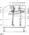
- a dough processing plant 1 is used for portioning and for working dough, for example in the production of bread.
- dough is filled in a feed hopper 2.
- a bottom-side outlet opening 3 of the feed hopper 2 communicates with a delivery chamber 4 in which a delivery piston 5 runs horizontally.
- the horizontal conveying movement of the delivery piston 5 is driven by a crank mechanism 6.
- a first lever arm 7 is articulated on a conveying chamber 4 facing away from the end of the delivery piston 5, which is rotatably connected at its other end with a pivot shaft 8.
- a second lever arm 9 which is articulated at its other end to a first connecting rod portion 10 of a connecting rod 11.
- the first connecting rod portion 10 is articulated to a second connecting rod portion 14.
- the arrangement of the load cell 13 in the connecting member 12 is such that by means of the load cell 13, the pressure can be measured, the two connecting rod sections 10, 14 exert on each other in the conveying movement of the delivery piston 5.
- Via a signal line 15, the load cell 13 is connected to a control device 16 in connection.
- the control device 16 has a rewritable memory 16 a.
- Load cells on the type of load cell 13 are known.
- the change in shape of the load cell 13 is a measure of the pressure acting on them. This change in shape can capacitive, inductive or by the Measurement of an electrical resistance change, for example, of strain gauges are measured.
- the two connecting rod sections 10, 14 and the connecting member 12 with the load cell 13 are guided in a connecting rod housing 17.
- the remote from the connecting member 12 end of the second connecting rod portion 14 is articulated to a crankshaft 18 which is driven via a drive chain 19 by a drive shaft 20 of a delivery piston drive motor 21.
- the control device 16 is connected via a control line 22.
- the dough is through in the Fig. 1 to 3 pressed to the right conveyor piston 5 pressed against Portionierhuntn 23, the jacket walls of portioning cylinders 24 are formed.
- the Portionierhuntn 23 put in the Fig. 1 to 3 the delivery room 4 to the right.
- the portioning chambers 23 are delimited by portioning pistons 25.
- the dough processing plant 1 are perpendicular to the plane of the Fig. 1 to 3 a plurality of portioning units each having a portioning chamber 23, a portioning cylinder 24 and a portioning piston 25 arranged one behind the other. To describe the dough processing plant, it will suffice if a single such portioning unit is described below, since the other portioning units are also constructed.
- the portioning piston 25 is arranged at its end remote from the pumping chamber 4 end to a portioning crankshaft 26, which in the Fig. 1 to 3 is driven in a manner not shown.
- a portioning crankshaft 26 is arranged at its end remote from the pumping chamber 4 end to a portioning crankshaft 26, which in the Fig. 1 to 3 is driven in a manner not shown.
- a Portionierhub the Portionierkolben 25 adjustable, whereby a desired volume of portioned dough pieces can be achieved.
- the Portioniericaen are arranged in a flat slide box 27, the vertical slide wall 28 flush with end wall portions of the conveying chamber 4 limiting and the delivery piston 5 leading support portion 29 of the dough treatment plant 1 is applied.
- the flat slide box 27 is displaceable along the vertical guide of the slide wall 28 on the support portion 29 for portioning the dough.
- the flat slide box 27 is articulated to a flat slide box connecting rod 30, which is articulated at its other end to a flat slide box crankshaft 31.
- the latter is driven via a drive chain 32 by a drive shaft 33 of a flat slide box drive motor 34.
- Fig. 1 to 3 illustrate the portioning of dough pieces 35 with the dough processing plant.
- Fig. 1 shows the dough processing plant 1 in a dough-suction phase in which the delivery piston 5 is fully retracted to the left and in which the Portionierkolben 25 occupy a displaced position to the left, in which their piston walls flush with the pumping chamber 4 facing surface of the slide wall 28 complete.
- Fig. 2 shows the dough processing plant 1 during a dough-filling phase in which the sucked dough is compacted by moving the delivery piston 5 to the right and pressed in the direction of the Portionierhuntn 23.
- the portioning pistons 25 in the portioning cylinders 24 are displaced to the right by the portioning stroke predetermined by the portioning crankshaft 26, so that a desired dough volume can be collected in the portioning chambers 23.
- the pressure with which the delivery piston 5 presses in the dough-filling phase on the compacted dough in the delivery chamber 4 and in the Portionierhuntn 23 is measured by means of the load cell 13 and the signal line 15 transmitted to the control device 16. There, the measured pressure is compared with a stored in memory 16a of the controller 16 limit. When the measured with the load cell 13 pressure has reached the pressure limit, the depression of the dough is in the Portionierhuntn 23 completed by the delivery piston 5 and this is, for example in the position of Fig. 2 controlled by the control device 16 via the control line 22, stopped.
- the stored in the control device 16 pressure limit is particularly adapted to the dough recipe and also to the portion size.
- a pressure limit value can be selected by the user from a plurality of pressure limit values stored in the memory 16a.
- the flat slide box 27 is moved down to the position shown in FIG Fig. 3 spent showing the dough processing equipment 1 in a dough discharge phase.
- the Portionierkolben 25 are after relocation of the flat slide box 27 back into the in Fig. 3 shown displaced to the left position and thus push dough pieces 35 on a transfer conveyor belt 36, which is designed as deflected in a manner not shown continuous conveyor belt from.
- a transfer conveyor belt 36 which is designed as deflected in a manner not shown continuous conveyor belt from.
- the dough-knitting device 37 will be described below with additional reference to FIGS Fig. 4 to 9 described. It has an inner hollow cylindrical drum 38, which is rotatably connected via a support frame 39 with a central active drum shaft 40. Coaxially around the inner active drum 38, an outer hollow-cylindrical active drum 41, also referred to as a chamber drum, is arranged. This is arranged so as to be rotatable about the operating drum shaft 40 relative to the inner operating drum 38 on the operating drum shaft 40.
- the outer active drum 41 has openings 42 in a known manner. These are open to the outside and inwardly and are bounded on the inside by the outer wall of the inner drum 38.
- the perforations 42 are limited to the outside by a spectrum 43 of a kneading / conveyor belt 44, which in this peripheral portion the outer active drum 41 is applied.
- the apertures 42 which are bounded on all sides in this peripheral section form active cells 45.
- the kneading / conveyor belt 44 is designed as a multiply deflected endless conveyor belt.
- the inner action drum 38 and the outer action drum 41 perform an effective movement for the action of the dough relative to one another, which is driven by an active drive designated overall by the reference numeral 46.
- a non-illustrated active drive motor acts via a transmission belt 47 on a transmission disc 48 which is rotatably connected to a first transmission shaft 49. The latter is connected to a drive-side shaft of a Wirkantriebsgetriebes 50.
- the Wirkantriebsgetriebe 50 transmits the rotation of the transmission shaft 49 in a rotation of a transmission shaft 51 which is arranged between the transmission shaft 49 and the reel shaft 40 and whose axis of rotation 52 is perpendicular to the axis of rotation of the reel drum 40.
- an eccentric shaft 53 In a bore of the transmission shaft 51, an eccentric shaft 53, whose axis of rotation 54 extends parallel to the axis of rotation of the transmission shaft 51 and to this has a distance which in the Fig. 4 and 7 is designated E 2 .
- the eccentric shaft 53 is pivotable relative to the transmission shaft 51 about its axis of rotation 54.
- This Verschwenkweg is limited by a stop body 54a, which is rotatably connected to the eccentric shaft 53 and cooperates with a counter stop body 54b, which is designed as a stage in a stop body 54a facing end wall of the transmission shaft 51.
- Another counter-stop body 54c is also embodied in the end wall of the transmission shaft 51.
- the eccentric shaft 53 is connected via an eccentric connecting member 55 with a further eccentric shaft 56 in connection, whose axis of rotation 57 is arranged parallel to the axes of rotation 52 and 54.
- the distance between the axes of rotation 54, 57 of the eccentric shafts 53, 56 is in Fig. 4 denoted by E 1 .
- the eccentric shaft 56 is in relation to the transmission shaft 51 in the position of the active drive 46 in the 4 to 6 arranged such that the axis of rotation 52 of the transmission shaft 51 to the axis of rotation 57 of the eccentric shaft 56 has the distance E 1 + E 2 .
- the eccentric shaft 56 is connected via a ball joint with a transmission member 58.
- the latter is via a further transmission element 59, which is rotatably mounted about the Wektrommelwelle 40, with the outer active drum 41 in connection.
- the two transmission members 58, 59 represent a second and a third drive component of the active drive 46 and have the following function: Firstly, via the transmission members 58, 59, the rotational movement of the transmission shaft 59 is transferred into a rotary movement of the outer drum 41 about the operating drum shaft 40. The rotational movements of the two power rollers 38, 41 to the Wektrommelwelle 40 are independent of each other. In this sense, the transfer members 58, 59 constitute a second drive component of the drive 46. Further, the transfer members 58, 59 also transmit a movement component of the outer drive drum 41 relative to the inner drive drum 38 parallel to the drive drum shaft 40, driven by the rotation of the eccentric shaft 56 about Transmission shaft 51.
- the transmission members 58, 59 a third drive component of the active drive 46.
- the rotation of the outer active drum 41 to the inner drive drum 38 and the movement of the outer active drum 41 relative to the inner active drum 38 with component of movement parallel to the longitudinal axis of the reel shaft 40 are coordinated so that the openings 42 and in particular the active cells perform a circular movement relative to the openings 42 delimiting wall of the inner active drum 38 and relative to the active spectrum 43 of the active conveyor belt 44.
- the dough pieces 35 in the kneading cells are knitted in this way, whereby the previously unformed dough piece 35 is brought into a spherical shape.
- a relative pivoting of the two eccentric shafts 53, 56 to each other by 180 ° is possible.
- the distances E 1 and E 2 subtract from each other, so that the axis of rotation 52 of the transmission shaft 51 and the axis of rotation 57 of the eccentric shaft 56 to each other at a distance of E 1 - E 2 have.
- the eccentricity of the eccentric shaft 57 is reduced to the transmission shaft 51 of the larger eccentricity E 1 + E 2 to the smaller eccentricity E 1 - E 2 . Accordingly, the amount of the movement component of the relative movement of the outer active drum 41 to the inner active drum 38 is reduced parallel to the longitudinal axis of the reeling drum shaft 40.
- the dough pieces 35 leave the active cells and are transferred to a conveying strand 60 of the kneading / conveyor belt 44 and leave a housing 61 of the dough processing plant 1 through a corresponding discharge opening.
Landscapes
- Life Sciences & Earth Sciences (AREA)
- Engineering & Computer Science (AREA)
- Food Science & Technology (AREA)
- Manufacturing And Processing Devices For Dough (AREA)
Claims (5)
- Installation de traitement de pâte (1)- comprenant un dispositif d'amenée de pâte (2),- comprenant un dispositif de division de pâte en portions (5, 22 à 27), qui comporte :-- au moins un piston de refoulement (5), qui presse la pâte amenée dans au moins une chambre de division en portions (23),-- au moins un dispositif d'entraînement (6 à 21) pour le piston de refoulement (5),- comprenant un dispositif de transfert (36),au moins un composant d'entraînement (11) du dispositif d'entraînement (6 à 21) pour le piston de refoulement (5) comprenant un dispositif de mesure de force (13), lequel est agencé de telle manière qu'il peut mesurer la force que le piston de refoulement (5) exerce sur la pâte lorsqu'une pression est appliquée sur cette dernière,
caractérisée en ce que
le dispositif de mesure de force (13) comporte au moins une jauge de contrainte,
un dispositif de façonnage de pâte (37) est prévu, le dispositif de transfert (36) transférant une portion de pâte (35) du dispositif de division de pâte en portions (5, 23 à 27) au dispositif de façonnage de pâte (37), et
un dispositif d'évacuation de pâte (60) est prévu. - Installation de traitement de pâte (1)- comprenant un dispositif d'amenée de pâte (2),- comprenant un dispositif de division de pâte en portions (5, 22 à 27), qui comporte :-- au moins un piston de refoulement (5), qui presse la pâte amenée dans au moins une chambre de division en portions (23),-- au moins un dispositif d'entraînement (6 à 21) pour le piston de refoulement (5),- comprenant un dispositif de façonnage de pâte (37),- comprenant un dispositif de transfert (36) qui transfère une portion de pâte (35) du dispositif de division de pâte en portions (5, 23 à 27) au dispositif de fermentation de pâte (37) et- comprenant un dispositif d'évacuation de pâte (60),caractérisée en ce que
au moins un composant d'entraînement (11) du dispositif d'entraînement (6 à 21) pour le piston de refoulement (5) comprend un dispositif de mesure de force (13), lequel est agencé de telle manière qu'il peut mesurer la force que le piston de refoulement (5) exerce sur la pâte lorsqu'une pression est appliquée sur cette dernière, le dispositif de mesure de force (13) étant réalisé sous la forme d'un dynamomètre situé entre deux parties d'entraînement (10, 14) du dispositif d'entraînement (6 à 21). - Installation de traitement de pâte selon la revendication 2, caractérisée en ce que le dispositif de mesure de force (13) est agencé dans un boîtier tubulaire (17) entre deux sections (10, 14) de barre d'une barre d'entraînement (11), en particulier d'une bielle.
- Installation de traitement de pâte selon l'une quelconque des revendications précédentes, caractérisée par un dispositif de commande (16) qui est relié au dispositif de mesure de force (13) et au dispositif d'entraînement (6 à 21) et qui est conçu de telle manière que, lorsqu'une pression est exercée dans les chambres de division en portions (23), l'entraînement (21) du piston de refoulement (5) est arrêté dès qu'une pression mesurée par le dispositif de mesure de force (13) dépasse une valeur seuil de pression préréglée.
- Installation de traitement de pâte selon la revendication 4, caractérisée en ce que le dispositif de commande (16) comprend une mémoire de données (16a) pour une pluralité de valeurs seuils de force.
Applications Claiming Priority (2)
| Application Number | Priority Date | Filing Date | Title |
|---|---|---|---|
| DE10306437 | 2003-02-15 | ||
| DE10306437A DE10306437A1 (de) | 2003-02-15 | 2003-02-15 | Teigbearbeitungsanlage |
Publications (3)
| Publication Number | Publication Date |
|---|---|
| EP1447005A2 EP1447005A2 (fr) | 2004-08-18 |
| EP1447005A3 EP1447005A3 (fr) | 2007-06-13 |
| EP1447005B1 true EP1447005B1 (fr) | 2016-06-15 |
Family
ID=32668082
Family Applications (1)
| Application Number | Title | Priority Date | Filing Date |
|---|---|---|---|
| EP04000466.5A Expired - Lifetime EP1447005B1 (fr) | 2003-02-15 | 2004-01-13 | Installation de traitement de pâte |
Country Status (3)
| Country | Link |
|---|---|
| US (1) | US6883954B2 (fr) |
| EP (1) | EP1447005B1 (fr) |
| DE (1) | DE10306437A1 (fr) |
Cited By (1)
| Publication number | Priority date | Publication date | Assignee | Title |
|---|---|---|---|---|
| DE102018205461A1 (de) | 2018-04-11 | 2019-10-17 | Werner & Pfleiderer Lebensmitteltechnik Gmbh | Teigbearbeitungsanlage |
Families Citing this family (8)
| Publication number | Priority date | Publication date | Assignee | Title |
|---|---|---|---|---|
| DE10306438A1 (de) * | 2003-02-15 | 2004-08-26 | Werner & Pfleiderer Lebensmitteltechnik Gmbh | Teigbearbeitungsanlage |
| DE102008016246B4 (de) | 2008-03-27 | 2023-06-15 | Fortuna Maschinen Gmbh | Vorrichtung und Verfahren zum Wirken von Teiglingen |
| DE102008050956A1 (de) | 2008-10-10 | 2010-04-15 | Fortuna Maschinenbau Holding Ag | Vorrichtung und Verfahren zum Bearbeiten von Teiglingen |
| NL2002288C2 (nl) * | 2008-12-04 | 2010-06-07 | Kaak Joannes Hendrik Bernard | Werkwijze en samenstel voor het afmeten van deeg. |
| USD612666S1 (en) | 2009-02-26 | 2010-03-30 | King-Yuan Lin | Dough divider-rounder |
| US9635865B1 (en) * | 2015-05-18 | 2017-05-02 | Norman Schmidt | Dough feeder |
| US11986979B2 (en) | 2021-09-24 | 2024-05-21 | Aaron Engineered Process Equipment, Inc. | Double arm mixer extruder |
| DE102022211144A1 (de) * | 2022-10-20 | 2024-04-25 | Wp Kemper Gmbh | Teigbearbeitungsvorrichtung sowie Teigbearbeitungsanlage mit einer derartigen Teigbearbeitungsvorrichtung |
Family Cites Families (22)
| Publication number | Priority date | Publication date | Assignee | Title |
|---|---|---|---|---|
| GB697034A (en) * | 1951-03-16 | 1953-09-16 | Thomas Barker & Sons Ltd | Improvements in or relating to dough-dividing and like machines |
| DE1922549A1 (de) | 1969-05-02 | 1970-11-19 | Briem Hengler Cronemeyer | Vorrichtung zur Bearbeitung teigartiger Massen mit periodisch bewegten Maschinenteilen,insbesondere Teigstanze |
| DE2315977A1 (de) * | 1973-03-30 | 1974-10-24 | Eberhardt Gmbh G L | Vorrichtung zum bilden von teigportionen |
| DE2438316C2 (de) * | 1974-08-09 | 1984-11-08 | Herbert Schröder | Maschine zum teilen und wirken von teigstuecken |
| FR2341842A1 (fr) * | 1976-02-23 | 1977-09-16 | Talleres Balart Sa | Bielle hydraulique pour machine de distribution commandee d'une masse de materiau |
| NL7604941A (nl) * | 1976-05-07 | 1977-11-09 | Hurkmans Antonius | Werkwijze en installatie voor het afleveren van gedoseerde porties van een substantie. |
| GB1593013A (en) * | 1978-01-24 | 1981-07-15 | Herring M T A | Method of portioning and portioning machine |
| US4177030A (en) * | 1978-05-01 | 1979-12-04 | Amf Incorporated | Dough divider |
| DE3319666C2 (de) * | 1983-05-31 | 1985-04-11 | Fr. Winkler KG Spezialfabrik für Bäckereimaschinen und Backöfen, 7730 Villingen-Schwenningen | Automatische Teigteil- und Wirkmaschine |
| CH677309A5 (fr) * | 1987-11-27 | 1991-05-15 | Buehler Ag | |
| DE3821045C1 (fr) * | 1988-06-22 | 1989-04-27 | Werner & Pfleiderer Gmbh, 7000 Stuttgart, De | |
| AT392195B (de) * | 1988-12-20 | 1991-02-11 | Koenig Helmut | Vorrichtung zum wirken von portionierten teigstuecken |
| DE3911521A1 (de) * | 1989-04-08 | 1990-10-11 | Fr Winkler Gmbh & Co Kg Spezia | Maschine zum teilen von teigstuecken |
| JPH044837A (ja) * | 1990-04-23 | 1992-01-09 | Rheon Autom Mach Co Ltd | ベイキング生地シートの製造方法及び装置 |
| CA2113264C (fr) * | 1991-07-12 | 1997-03-25 | Helmut Konig | Dispositif de decoupage de portions de pate |
| AT397024B (de) * | 1991-07-12 | 1994-01-25 | Koenig Helmut | Vorrichtung zum behandeln von teig |
| NL9200425A (nl) * | 1992-03-06 | 1993-10-01 | Holtkamp Holding Bv | Doseerinrichting voor deeg. |
| NO940868L (no) * | 1993-03-29 | 1994-09-30 | Bfe Ltd | Fremgangsmåte og anordning for brödbaking |
| DE19624401B4 (de) * | 1996-06-19 | 2009-05-07 | Werner & Pfleiderer Lebensmitteltechnik Gmbh | Teigverarbeitungsanlage |
| DE19640176A1 (de) * | 1996-09-28 | 1998-04-02 | Werner & Pfleiderer Lebensmitt | Teigteil-Maschine |
| IT1294110B1 (it) * | 1997-01-02 | 1999-03-22 | Antonio Cimenti | Porzionatrice per paste alimentari |
| DE19858169A1 (de) * | 1998-12-16 | 2000-06-29 | Josef Helmstaedter | Verfahren sowie Vorrichtung zum Portionieren von Teig zu Teiglingen |
-
2003
- 2003-02-15 DE DE10306437A patent/DE10306437A1/de not_active Withdrawn
-
2004
- 2004-01-13 EP EP04000466.5A patent/EP1447005B1/fr not_active Expired - Lifetime
- 2004-02-13 US US10/777,628 patent/US6883954B2/en not_active Expired - Fee Related
Cited By (2)
| Publication number | Priority date | Publication date | Assignee | Title |
|---|---|---|---|---|
| DE102018205461A1 (de) | 2018-04-11 | 2019-10-17 | Werner & Pfleiderer Lebensmitteltechnik Gmbh | Teigbearbeitungsanlage |
| DE102018205461B4 (de) | 2018-04-11 | 2021-07-22 | Backnet Gmbh | Teigbearbeitungsanlage |
Also Published As
| Publication number | Publication date |
|---|---|
| US6883954B2 (en) | 2005-04-26 |
| EP1447005A2 (fr) | 2004-08-18 |
| US20040159247A1 (en) | 2004-08-19 |
| EP1447005A3 (fr) | 2007-06-13 |
| DE10306437A1 (de) | 2004-08-26 |
Similar Documents
| Publication | Publication Date | Title |
|---|---|---|
| EP1447005B1 (fr) | Installation de traitement de pâte | |
| EP1449438B1 (fr) | Installation de traitement de pâte | |
| EP1900526B1 (fr) | Dispositif de commande d'amenée de tissu d'un dispositif de nettoyage pour cylindre d'imprimante | |
| EP2369311B1 (fr) | Unité de dosage pour substances pouvant s'écouler | |
| DE2603964B2 (de) | Vorrichtung zum entleeren eines schuettgutbunkers | |
| EP1363063A2 (fr) | Lubricateur | |
| EP2901860B1 (fr) | Diviseuse pour pâtes | |
| EP0721737B1 (fr) | Machine à diviser et bouler la pâte | |
| DE3545673A1 (de) | Portioniermaschine | |
| EP2071955B1 (fr) | Installation de traitement de pâte | |
| EP2782452B1 (fr) | Ensemble de pesée de précision pour déporter des portions de pâte | |
| EP0115069B1 (fr) | Procédé et dispositif pour emballer des flocons de fibre en balles | |
| DE19914499C2 (de) | Fördervorrichtung für pastöse Massen und Verfahren zur Bestimmung deren Luftinhaltes | |
| DE2023927A1 (de) | Verfahren und Vorrichtung zum Aufschneiden von Lebensmittel-Laiben in Scheiben | |
| EP3728761B1 (fr) | Manipulateur avec mecanisme d'entrainement en rotation | |
| EP1196044B1 (fr) | Dispositif pour realiser un produit de consommation | |
| EP2660038B1 (fr) | Presse pour le briquetage de matériau granuleux | |
| AT360457B (de) | Maschine zum herstellen von gleichen teig- teilchen | |
| EP4356738A2 (fr) | Dispositif de traitement de pâte ainsi qu'installation de traitement de pâte dotée d'un tel dispositif de traitement de pâte | |
| DE2907568C2 (de) | Maschine zum Herstellen von gleichen Teigteilchen | |
| AT400381B (de) | Vorrichtung zur herstellung von teigportionen für rustikale brötchen | |
| WO1994019952A2 (fr) | Machine servant a travailler des portions de pate | |
| WO2014040878A1 (fr) | Machine de portionnement de pâte et groupe structural en tant que partie d'une telle machine de portionnement de pâte | |
| DE3322200C1 (de) | Verteilmaschine | |
| EP1502493A1 (fr) | Dispositif pour envelopper ou emballer, particulièrement pour des balles agricoles |
Legal Events
| Date | Code | Title | Description |
|---|---|---|---|
| PUAI | Public reference made under article 153(3) epc to a published international application that has entered the european phase |
Free format text: ORIGINAL CODE: 0009012 |
|
| AK | Designated contracting states |
Kind code of ref document: A2 Designated state(s): AT BE BG CH CY CZ DE DK EE ES FI FR GB GR HU IE IT LI LU MC NL PT RO SE SI SK TR |
|
| AX | Request for extension of the european patent |
Extension state: AL LT LV MK |
|
| PUAL | Search report despatched |
Free format text: ORIGINAL CODE: 0009013 |
|
| AK | Designated contracting states |
Kind code of ref document: A3 Designated state(s): AT BE BG CH CY CZ DE DK EE ES FI FR GB GR HU IE IT LI LU MC NL PT RO SE SI SK TR |
|
| AX | Request for extension of the european patent |
Extension state: AL LT LV MK |
|
| 17P | Request for examination filed |
Effective date: 20071025 |
|
| AKX | Designation fees paid |
Designated state(s): AT BE BG CH CY CZ DE DK EE ES FI FR GB GR HU IE IT LI LU MC NL PT RO SE SI SK TR |
|
| 17Q | First examination report despatched |
Effective date: 20090213 |
|
| GRAP | Despatch of communication of intention to grant a patent |
Free format text: ORIGINAL CODE: EPIDOSNIGR1 |
|
| INTG | Intention to grant announced |
Effective date: 20160204 |
|
| GRAS | Grant fee paid |
Free format text: ORIGINAL CODE: EPIDOSNIGR3 |
|
| GRAA | (expected) grant |
Free format text: ORIGINAL CODE: 0009210 |
|
| AK | Designated contracting states |
Kind code of ref document: B1 Designated state(s): AT BE BG CH CY CZ DE DK EE ES FI FR GB GR HU IE IT LI LU MC NL PT RO SE SI SK TR |
|
| REG | Reference to a national code |
Ref country code: CH Ref legal event code: EP Ref country code: GB Ref legal event code: FG4D Free format text: NOT ENGLISH |
|
| REG | Reference to a national code |
Ref country code: IE Ref legal event code: FG4D Free format text: LANGUAGE OF EP DOCUMENT: GERMAN |
|
| REG | Reference to a national code |
Ref country code: AT Ref legal event code: REF Ref document number: 806030 Country of ref document: AT Kind code of ref document: T Effective date: 20160715 |
|
| REG | Reference to a national code |
Ref country code: DE Ref legal event code: R096 Ref document number: 502004015227 Country of ref document: DE |
|
| REG | Reference to a national code |
Ref country code: NL Ref legal event code: MP Effective date: 20160615 |
|
| PG25 | Lapsed in a contracting state [announced via postgrant information from national office to epo] |
Ref country code: FI Free format text: LAPSE BECAUSE OF FAILURE TO SUBMIT A TRANSLATION OF THE DESCRIPTION OR TO PAY THE FEE WITHIN THE PRESCRIBED TIME-LIMIT Effective date: 20160615 |
|
| PG25 | Lapsed in a contracting state [announced via postgrant information from national office to epo] |
Ref country code: GR Free format text: LAPSE BECAUSE OF FAILURE TO SUBMIT A TRANSLATION OF THE DESCRIPTION OR TO PAY THE FEE WITHIN THE PRESCRIBED TIME-LIMIT Effective date: 20160916 Ref country code: SE Free format text: LAPSE BECAUSE OF FAILURE TO SUBMIT A TRANSLATION OF THE DESCRIPTION OR TO PAY THE FEE WITHIN THE PRESCRIBED TIME-LIMIT Effective date: 20160615 Ref country code: NL Free format text: LAPSE BECAUSE OF FAILURE TO SUBMIT A TRANSLATION OF THE DESCRIPTION OR TO PAY THE FEE WITHIN THE PRESCRIBED TIME-LIMIT Effective date: 20160615 |
|
| PG25 | Lapsed in a contracting state [announced via postgrant information from national office to epo] |
Ref country code: EE Free format text: LAPSE BECAUSE OF FAILURE TO SUBMIT A TRANSLATION OF THE DESCRIPTION OR TO PAY THE FEE WITHIN THE PRESCRIBED TIME-LIMIT Effective date: 20160615 Ref country code: CZ Free format text: LAPSE BECAUSE OF FAILURE TO SUBMIT A TRANSLATION OF THE DESCRIPTION OR TO PAY THE FEE WITHIN THE PRESCRIBED TIME-LIMIT Effective date: 20160615 Ref country code: SK Free format text: LAPSE BECAUSE OF FAILURE TO SUBMIT A TRANSLATION OF THE DESCRIPTION OR TO PAY THE FEE WITHIN THE PRESCRIBED TIME-LIMIT Effective date: 20160615 Ref country code: RO Free format text: LAPSE BECAUSE OF FAILURE TO SUBMIT A TRANSLATION OF THE DESCRIPTION OR TO PAY THE FEE WITHIN THE PRESCRIBED TIME-LIMIT Effective date: 20160615 |
|
| PG25 | Lapsed in a contracting state [announced via postgrant information from national office to epo] |
Ref country code: PT Free format text: LAPSE BECAUSE OF FAILURE TO SUBMIT A TRANSLATION OF THE DESCRIPTION OR TO PAY THE FEE WITHIN THE PRESCRIBED TIME-LIMIT Effective date: 20161017 Ref country code: ES Free format text: LAPSE BECAUSE OF FAILURE TO SUBMIT A TRANSLATION OF THE DESCRIPTION OR TO PAY THE FEE WITHIN THE PRESCRIBED TIME-LIMIT Effective date: 20160615 |
|
| REG | Reference to a national code |
Ref country code: DE Ref legal event code: R097 Ref document number: 502004015227 Country of ref document: DE |
|
| PLBE | No opposition filed within time limit |
Free format text: ORIGINAL CODE: 0009261 |
|
| STAA | Information on the status of an ep patent application or granted ep patent |
Free format text: STATUS: NO OPPOSITION FILED WITHIN TIME LIMIT |
|
| 26N | No opposition filed |
Effective date: 20170316 |
|
| PG25 | Lapsed in a contracting state [announced via postgrant information from national office to epo] |
Ref country code: BE Free format text: LAPSE BECAUSE OF NON-PAYMENT OF DUE FEES Effective date: 20170131 Ref country code: DK Free format text: LAPSE BECAUSE OF FAILURE TO SUBMIT A TRANSLATION OF THE DESCRIPTION OR TO PAY THE FEE WITHIN THE PRESCRIBED TIME-LIMIT Effective date: 20160615 |
|
| REG | Reference to a national code |
Ref country code: DE Ref legal event code: R119 Ref document number: 502004015227 Country of ref document: DE |
|
| PG25 | Lapsed in a contracting state [announced via postgrant information from national office to epo] |
Ref country code: SI Free format text: LAPSE BECAUSE OF FAILURE TO SUBMIT A TRANSLATION OF THE DESCRIPTION OR TO PAY THE FEE WITHIN THE PRESCRIBED TIME-LIMIT Effective date: 20160615 |
|
| REG | Reference to a national code |
Ref country code: CH Ref legal event code: PL |
|
| GBPC | Gb: european patent ceased through non-payment of renewal fee |
Effective date: 20170113 |
|
| PG25 | Lapsed in a contracting state [announced via postgrant information from national office to epo] |
Ref country code: MC Free format text: LAPSE BECAUSE OF FAILURE TO SUBMIT A TRANSLATION OF THE DESCRIPTION OR TO PAY THE FEE WITHIN THE PRESCRIBED TIME-LIMIT Effective date: 20160615 |
|
| REG | Reference to a national code |
Ref country code: FR Ref legal event code: ST Effective date: 20170929 |
|
| PG25 | Lapsed in a contracting state [announced via postgrant information from national office to epo] |
Ref country code: LI Free format text: LAPSE BECAUSE OF NON-PAYMENT OF DUE FEES Effective date: 20170131 Ref country code: FR Free format text: LAPSE BECAUSE OF NON-PAYMENT OF DUE FEES Effective date: 20170131 Ref country code: CH Free format text: LAPSE BECAUSE OF NON-PAYMENT OF DUE FEES Effective date: 20170131 |
|
| REG | Reference to a national code |
Ref country code: IE Ref legal event code: MM4A |
|
| PG25 | Lapsed in a contracting state [announced via postgrant information from national office to epo] |
Ref country code: LU Free format text: LAPSE BECAUSE OF NON-PAYMENT OF DUE FEES Effective date: 20170113 Ref country code: DE Free format text: LAPSE BECAUSE OF NON-PAYMENT OF DUE FEES Effective date: 20170801 Ref country code: GB Free format text: LAPSE BECAUSE OF NON-PAYMENT OF DUE FEES Effective date: 20170113 |
|
| REG | Reference to a national code |
Ref country code: BE Ref legal event code: MM Effective date: 20170131 |
|
| PG25 | Lapsed in a contracting state [announced via postgrant information from national office to epo] |
Ref country code: IT Free format text: LAPSE BECAUSE OF NON-PAYMENT OF DUE FEES Effective date: 20170113 Ref country code: IE Free format text: LAPSE BECAUSE OF NON-PAYMENT OF DUE FEES Effective date: 20170113 |
|
| REG | Reference to a national code |
Ref country code: AT Ref legal event code: MM01 Ref document number: 806030 Country of ref document: AT Kind code of ref document: T Effective date: 20170113 |
|
| PG25 | Lapsed in a contracting state [announced via postgrant information from national office to epo] |
Ref country code: AT Free format text: LAPSE BECAUSE OF NON-PAYMENT OF DUE FEES Effective date: 20170113 |
|
| PG25 | Lapsed in a contracting state [announced via postgrant information from national office to epo] |
Ref country code: HU Free format text: LAPSE BECAUSE OF FAILURE TO SUBMIT A TRANSLATION OF THE DESCRIPTION OR TO PAY THE FEE WITHIN THE PRESCRIBED TIME-LIMIT; INVALID AB INITIO Effective date: 20040113 |
|
| PG25 | Lapsed in a contracting state [announced via postgrant information from national office to epo] |
Ref country code: BG Free format text: LAPSE BECAUSE OF FAILURE TO SUBMIT A TRANSLATION OF THE DESCRIPTION OR TO PAY THE FEE WITHIN THE PRESCRIBED TIME-LIMIT Effective date: 20160615 |
|
| PG25 | Lapsed in a contracting state [announced via postgrant information from national office to epo] |
Ref country code: CY Free format text: LAPSE BECAUSE OF NON-PAYMENT OF DUE FEES Effective date: 20160615 |
|
| PG25 | Lapsed in a contracting state [announced via postgrant information from national office to epo] |
Ref country code: TR Free format text: LAPSE BECAUSE OF FAILURE TO SUBMIT A TRANSLATION OF THE DESCRIPTION OR TO PAY THE FEE WITHIN THE PRESCRIBED TIME-LIMIT Effective date: 20160615 |