EP1448411B1 - Dispositif de protection d'un passager dans un vehicule - Google Patents
Dispositif de protection d'un passager dans un vehicule Download PDFInfo
- Publication number
- EP1448411B1 EP1448411B1 EP02791741A EP02791741A EP1448411B1 EP 1448411 B1 EP1448411 B1 EP 1448411B1 EP 02791741 A EP02791741 A EP 02791741A EP 02791741 A EP02791741 A EP 02791741A EP 1448411 B1 EP1448411 B1 EP 1448411B1
- Authority
- EP
- European Patent Office
- Prior art keywords
- air bag
- protection device
- occupant protection
- hinged
- support cover
- Prior art date
- Legal status (The legal status is an assumption and is not a legal conclusion. Google has not performed a legal analysis and makes no representation as to the accuracy of the status listed.)
- Expired - Lifetime
Links
- 239000011324 bead Substances 0.000 claims description 6
- 230000001681 protective effect Effects 0.000 claims description 5
- 230000003313 weakening effect Effects 0.000 claims description 5
- 230000003014 reinforcing effect Effects 0.000 claims description 4
- 239000004744 fabric Substances 0.000 claims description 3
- 239000000463 material Substances 0.000 claims description 2
- 239000002344 surface layer Substances 0.000 claims 3
- 230000015572 biosynthetic process Effects 0.000 claims 1
- 239000011229 interlayer Substances 0.000 claims 1
- 239000010410 layer Substances 0.000 claims 1
- 230000001960 triggered effect Effects 0.000 abstract description 2
- 238000005187 foaming Methods 0.000 description 4
- 238000003860 storage Methods 0.000 description 4
- 238000005253 cladding Methods 0.000 description 3
- 239000006260 foam Substances 0.000 description 2
- 238000005452 bending Methods 0.000 description 1
- 230000001419 dependent effect Effects 0.000 description 1
- 238000011161 development Methods 0.000 description 1
- 230000018109 developmental process Effects 0.000 description 1
- 230000002349 favourable effect Effects 0.000 description 1
- 239000004088 foaming agent Substances 0.000 description 1
- 238000002347 injection Methods 0.000 description 1
- 239000007924 injection Substances 0.000 description 1
- 238000004519 manufacturing process Methods 0.000 description 1
- 238000000034 method Methods 0.000 description 1
- 230000003287 optical effect Effects 0.000 description 1
- 230000035515 penetration Effects 0.000 description 1
- 238000003466 welding Methods 0.000 description 1
Images


Classifications
-
- B—PERFORMING OPERATIONS; TRANSPORTING
- B60—VEHICLES IN GENERAL
- B60R—VEHICLES, VEHICLE FITTINGS, OR VEHICLE PARTS, NOT OTHERWISE PROVIDED FOR
- B60R21/00—Arrangements or fittings on vehicles for protecting or preventing injuries to occupants or pedestrians in case of accidents or other traffic risks
- B60R21/02—Occupant safety arrangements or fittings, e.g. crash pads
- B60R21/16—Inflatable occupant restraints or confinements designed to inflate upon impact or impending impact, e.g. air bags
- B60R21/26—Inflatable occupant restraints or confinements designed to inflate upon impact or impending impact, e.g. air bags characterised by the inflation fluid source or means to control inflation fluid flow
- B60R21/261—Inflatable occupant restraints or confinements designed to inflate upon impact or impending impact, e.g. air bags characterised by the inflation fluid source or means to control inflation fluid flow with means other than bag structure to diffuse or guide inflation fluid
-
- B—PERFORMING OPERATIONS; TRANSPORTING
- B60—VEHICLES IN GENERAL
- B60R—VEHICLES, VEHICLE FITTINGS, OR VEHICLE PARTS, NOT OTHERWISE PROVIDED FOR
- B60R21/00—Arrangements or fittings on vehicles for protecting or preventing injuries to occupants or pedestrians in case of accidents or other traffic risks
- B60R21/02—Occupant safety arrangements or fittings, e.g. crash pads
- B60R21/16—Inflatable occupant restraints or confinements designed to inflate upon impact or impending impact, e.g. air bags
- B60R21/20—Arrangements for storing inflatable members in their non-use or deflated condition; Arrangement or mounting of air bag modules or components
- B60R21/205—Arrangements for storing inflatable members in their non-use or deflated condition; Arrangement or mounting of air bag modules or components in dashboards
-
- B—PERFORMING OPERATIONS; TRANSPORTING
- B60—VEHICLES IN GENERAL
- B60R—VEHICLES, VEHICLE FITTINGS, OR VEHICLE PARTS, NOT OTHERWISE PROVIDED FOR
- B60R21/00—Arrangements or fittings on vehicles for protecting or preventing injuries to occupants or pedestrians in case of accidents or other traffic risks
- B60R21/02—Occupant safety arrangements or fittings, e.g. crash pads
- B60R21/16—Inflatable occupant restraints or confinements designed to inflate upon impact or impending impact, e.g. air bags
- B60R21/20—Arrangements for storing inflatable members in their non-use or deflated condition; Arrangement or mounting of air bag modules or components
- B60R21/215—Arrangements for storing inflatable members in their non-use or deflated condition; Arrangement or mounting of air bag modules or components characterised by the covers for the inflatable member
- B60R21/2165—Arrangements for storing inflatable members in their non-use or deflated condition; Arrangement or mounting of air bag modules or components characterised by the covers for the inflatable member characterised by a tear line for defining a deployment opening
-
- B—PERFORMING OPERATIONS; TRANSPORTING
- B60—VEHICLES IN GENERAL
- B60R—VEHICLES, VEHICLE FITTINGS, OR VEHICLE PARTS, NOT OTHERWISE PROVIDED FOR
- B60R21/00—Arrangements or fittings on vehicles for protecting or preventing injuries to occupants or pedestrians in case of accidents or other traffic risks
- B60R21/02—Occupant safety arrangements or fittings, e.g. crash pads
- B60R21/16—Inflatable occupant restraints or confinements designed to inflate upon impact or impending impact, e.g. air bags
- B60R21/20—Arrangements for storing inflatable members in their non-use or deflated condition; Arrangement or mounting of air bag modules or components
- B60R21/217—Inflation fluid source retainers, e.g. reaction canisters; Connection of bags, covers, diffusers or inflation fluid sources therewith or together
- B60R21/2171—Inflation fluid source retainers, e.g. reaction canisters; Connection of bags, covers, diffusers or inflation fluid sources therewith or together specially adapted for elongated cylindrical or bottle-like inflators with a symmetry axis perpendicular to the main direction of bag deployment, e.g. extruded reaction canisters
Definitions
- the invention relates to an occupant protection device for a vehicle with one comprising an airbag holder and a folded inflatable airbag Airbag unit and one of a dimensionally stable support member and a by the airbag in the event of triggering rupturable cladding existing, in particular formed by an instrument panel vehicle interior to concealed intake of the airbag unit.
- an occupant protection device for a vehicle with one comprising an airbag holder and a folded inflatable airbag Airbag unit and one of a dimensionally stable support member and a by the airbag in the event of triggering rupturable cladding existing, in particular formed by an instrument panel vehicle interior to concealed intake of the airbag unit.
- EP 1 106 446 A is Such a protective device known to the preamble of Claim 1 or 2 corresponds.
- the airbag unit is from the passenger compartment invisible integrated into the instrument panel to design requirements to satisfy and at the same time gain back space.
- the Airbag or gas bag lies as a folded package directly behind the flexible panel, by which he in case of triggering tearing an exit area penetrates.
- characteristics has the direct support of the fairing on the folded airbag.
- the invention has the object, in a Vehicle interior integrated airbag system to improve to that the disadvantages in the prior art are overcome and a good one Surface quality is ensured with high reliability.
- the bag holder a support cover for spanning a stowage chamber for the airbag, and in that the support cover from a top layer of the airbag to the panel out is covered.
- This ensures that the panel over the entire surface firmly supported is without elastically yielding zones in the airbag folding occur.
- the support cover forms a rigid abutment surface against intrusions from the passenger compartment while ensuring one consistent feel of the surface.
- foaming the panel a uniform support in the foaming tool is ensured.
- a variant of the invention with which the same advantages can be achieved sees suggest that the bag holder to one of a single cover layer of the airbag the cover has covered over support cover, and that one around the Support cover circumferential stowage chamber for the airbag by a at the Support part or support cover hinged hinged lid is covered.
- the support lid hinged lid are in particular concave contouring allows without these cover areas of the airbag would have to be spanned freely. It is also the hinged lid with release of an air bag outlet area to the vehicle interior folded down.
- the bag holder a preferably radially open annular space as a storage chamber for receiving limited an annular Faltenwulstes the airbag.
- This can be the Cover layer of the airbag are supplied with compressed gas centrally, while folded the folding layers of the airbag fabric laterally out of the annulus become.
- a further improvement in this regard is achieved in that the Support cover to release a release area for the airbag Vehicle interior folded down, preferably revolving folding edge having. It is advantageous if the annular folding edge or Hinged lid hinged over a linear wall weakening and through Edge cuts is divided into several edge segments. To the bending stiffness To increase, the folding edge or hinged lid at its from the Facing away from the back stiffened by reinforcing ribs be. For safety reasons, it is advantageous if the folding edge or Hinged lid over a flexurally soft flat material layer, preferably one glued or molded fabric blank on the support cover or the support member is secured.
- the bag holder in a Central region of the support lid with at least one through-flow opening, preferably a plurality of flow openings for inflating the Airbags is provided. It is advantageous if the flow openings for the deployment control of the airbag different flow areas and / or have orientations and / or spatially uneven are arranged distributed.
- the flange part limits one by means of a gas generator with gas for inflating the airbag acted upon central flow channel opposite a circumferential folding bead of the airbag.
- Another structurally advantageous embodiment provides that the flange is reinforced by lattice-shaped stiffening ribs.
- the flange is by a radial formed outwardly angled ring base. It is advantageous if the ring base at its free annular shoulder connecting means to the edge side Holding the airbag and attachment to the support member.
- the carrier part a the lining facing annular bearing surface for positive locking Has recording of the support cover or the hinged lid.
- the prefabricated airbag unit is in a receiving section used the support member and visible by applying the panel covered.
- a further advantageous embodiment provides that the cladding of a to the vehicle interior facing decorative skin and one on the decorative skin the carrier part supporting foamed intermediate layer, wherein the decorative skin in the area of the support lid or the hinged lid on the back is weakened by tearing lines for the passage of the airbag.
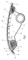
- the occupant protection device shown in the drawing comprises a by an airbag holder 10 and an airbag 12 folded therein Airbag unit 14, which on the passenger side in an instrument panel 16 of a motor vehicle is integrated.
- the instrument panel 16 consists in a conventional manner from a dimensionally stable planar support member 18th made of plastic, which on the visible side of a decorative skin 20, in particular a Slushformhaut including a foamed intermediate layer 22nd is covered.
- the airbag unit 14 shown in Fig. 1 can be prefabricated separately and before applying the decor skin 20 and foam layer 22 existing Insert panel 24 in a receiving section 26 of the support member 18.
- the bag holder 10 on a support cover 28, which is the one Breakthrough in the support member 18 limiting recording party 26 also in Falt Scheme the airbag 12 spans flat.
- the bag holder 10 as a total mushroom-shaped Structure on the back of the support cover 28 protruding Flange member 30 which on the support member 18 in the region of the receiving party 26 is flanged.
- the flange member 30 by a radial outwardly angled, formed in cross section L-shaped ring base, which at its free annular shoulder 32 via connecting means (mounting pin 34) is fixedly connected to the carrier part 26.
- the ring base 30 With its inner, adjacent to the support cover 28 ring portion 36th the ring base 30 defines a flow-through channel 38, which via a gas generator 40 with compressed gas for inflating the airbag 12 can be acted upon.
- the gas generator 40 is located in a generator trough 42, which At the edge gas-tight over the connecting means 34 of the flange 30 at the carrier section 26 is connected.
- the throughflow channel 38 opens via a flange part 30 stiffening grid-shaped rib structure 44 frontally at a central region 46 of the Support cover 28, which of a plurality of flow openings 48 for the gas outlet is broken.
- a wall area of the ring base 30 is provided with further flow openings 48 ' be.
- the support cover 28 has in its over the annular portion 36 of the flange 30 projecting area a folding edge 50, which in the case of triggering for releasing an outlet portion 52 for the folded airbag 12 to Vehicle interior is folded down.
- a folding edge 50 via a circumferential line-shaped wall weakening 54 at the central area 46 of the support cover 28 hinged.
- the folding edge 50 by radial edge cuts 56 in several Edge segments 58 divided. A tearing of the edge segments 58 is through one the wall weakening 54 cross, molded into the support cover 28 Tissue blank 60 reached ( Figure 3).
- To improve the flexural rigidity is the folding edge 50 facing away from the panel 24 at its Rear stiffened by reinforcing ribs 62.
- the air bag 12 has the support cover 28 at the front of the panel 24 towards covering, the lid edge embracing cover layer 64 and a adjoining annular fold 68 on.
- the annular fold 68 is located in a storage chamber 70, which through the folding edge 50 opposite the cover 24 is covered. Interior and bottom is the stagnation chamber 70 bounded by the flange portion 30 while the radial Outer limit in the installed state by the receiving section 26 of the Carrier part 18 is formed.
- the bag holder 10 is made of plastic as an injection molded part.
- the flange part 30 and the support cover 28 are formed separately and by friction welding firmly connected.
- the air bag 12 with his free edge on the annular shoulder 32 of the flange 30 expediently fixed by the fastening means 34 and folded into the storage chamber 70.
- To secure the folding bead 68 may serve a paper tape, not shown, which closes the storage space 70 radially outward.
- the thus prefabricated airbag unit 14 is then in the receiving section 26th used the support member 18, wherein one of the panel 24 facing annular bearing surface 74 of the support member 18 is a flush mount the support cover 28 allows.
- the thus completed support member 18 is in a foaming tool connected to the decorative skin 20 via the foamed intermediate layer 22.
- the cover layer 64 of the airbag 12 by an easily rupturable protective film 72 as shown in dashed lines in Fig. 1 and 3 for the sake of clarity is covered.
- the central region 46 of the Support cover 28 supported by the mold wall, so that no deformation occur. In this way, a uniform thickness of Foam layer 22 ensured without marks are visible.
- the gas flow is directed over a large area on the cover layer 64, so that the panel tears reliably under the deployment pressure.
- the decorative skin 20 in the area the support cover 28 back, for example, by U-shaped running Weakened lines.
- the airbag unfolds, it becomes the folding edge 50 unfolded and so the outlet portion 52 for the folding bead 68 completely Approved.
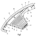
- FIG. 5 are functionally identical parts with the same reference numerals as described above tightened.
- the essential Difference is that instead of a folding edge one of the support cover 28 separate flap lid 150 is provided.
- This Hinged lid 150 is at an outer edge region 152, for example via a welded connection in the bearing surface 74 of the support member 18 is held firmly.
- the wall weakening 54 limits the edge region 152, so that the remaining cover part by the triggering airbag 12 to the vehicle interior can be swung out.
- the airbag 12 unfolds in the outlet area between hinged lid 150 and support cover 28.
Landscapes
- Engineering & Computer Science (AREA)
- Mechanical Engineering (AREA)
- Physics & Mathematics (AREA)
- Fluid Mechanics (AREA)
- Air Bags (AREA)
Abstract
Claims (20)
- Dispositif de protection d'un occupant pour un véhicule, comprenant une unité de coussin gonflable de sécurité (14) composée d'un support de coussin gonflable de sécurité (10) et d'un coussin gonflable de sécurité plié (12), et une partie intérieure de véhicule constituée d'un support indéformable (18) et d'un habillage (24) pouvant être déchiré par le déclenchement du coussin gonflable de sécurité (12), notamment formée par un tableau de bord (16), qui est destinée à abriter l'unité de coussin gonflable de sécurité (14) en la dissimulant, caractérisé en ce que le support (10) du coussin gonflable de sécurité présente un couvercle de soutien (28) recouvrant un compartiment de rangement (70) pour le coussin gonflable de sécurité (12), et en ce que le couvercle de soutien (28) est lui-même recouvert par une couche de recouvrement (64) du coussin gonflable de sécurité (12) en direction de l'habillage (24).
- Dispositif de protection d'un occupant pour un véhicule, comprenant une unité de coussin gonflable de sécurité (14) composée d'un support de coussin gonflable de sécurité (10) et d'un coussin gonflable de sécurité plié (12), et une partie intérieure de véhicule constituée par un support indéformable (18) et par un habillage (24) pouvant être déchiré par le déclenchement du coussin gonflable de sécurité (12), notamment formée par un tableau de bord (16), qui est destinée à abriter l'unité de coussin gonflable de sécurité (14) en la dissimulant, caractérisé en ce que le support (10) du coussin gonflable de sécurité présente un couvercle de soutien (28) recouvert en direction de l'habillage (24) par une couche de recouvrement (64) du coussin gonflable de sécurité (12), et en ce qu'un compartiment de rangement (70) pour le coussin gonflable de sécurité (12) faisant le tour du couvercle de soutien (28) est recouvert par un couvercle à charnière (50 ; 150) fixé de manière articulée sur le support (18) ou le couvercle de soutien.
- Dispositif de protection d'un occupant selon la revendication 1 ou 2, caractérisé en ce que le support (10) du coussin gonflable de sécurité délimite un espace annulaire de préférence ouvert radialement qui fait office de compartiment de rangement (70) destiné à recevoir un bourrelet annulaire en accordéon (68) du coussin gonflable de sécurité (12).
- Dispositif de protection d'un occupant selon la revendication 1 ou 3, caractérisé en ce que le couvercle de soutien (28) présente un rebord à charnière (50) de préférence circulaire pouvant être rabattu en direction de l'habitacle du véhicule, tout en libérant une zone de sortie (52) du compartiment de rangement (70) pour le coussin gonflable de sécurité (12).
- Dispositif de protection d'un occupant selon l'une des revendications 2 à 4, caractérisé en ce que le rebord à charnière (50) ou le couvercle à charnière (150) est fixé de façon articulée par le biais d'une ligne d'affaiblissement (54) de la paroi.
- Dispositif de protection d'un occupant selon l'une des revendications 2 à 5, caractérisé en ce que le rebord à charnière (50) ou le couvercle à charnière (150) est réalisé en forme d'anneau.
- Dispositif de protection d'un occupant selon l'une des revendications 2 à 6, caractérisé en ce que le rebord à charnière (50) ou le couvercle à charnière (150) est divisé en plusieurs segments périphériques (58) par des entailles (56) pratiquées dans le rebord.
- Dispositif de protection d'un occupant selon l'une des revendications 2 à 7, caractérisé en ce que le rebord à charnière (50) ou le couvercle à charnière (150) est rigidifié par des nervures de renforcement (62) sur sa face arrière opposée à l'habillage (24).
- Dispositif de protection d'un occupant selon l'une des revendications 2 à 8, caractérisé en ce que le rebord à charnière (50) ou le couvercle à charnière (150) est fixé au couvercle de soutien (28) ou au support (18) par une couche de matière souple (60), de préférence un morceau de tissu collé ou inclus dans le moule.
- Dispositif de protection d'un occupant selon l'une des revendications 1 à 9, caractérisé en ce que le support (10) du coussin gonflable de sécurité est muni dans une zone centrale (46) du couvercle de soutien (28) d'au moins une ouverture de passage, de préférence de plusieurs ouvertures de passage (48), afin de gonfler le coussin gonflable de sécurité (12).
- Dispositif de protection d'un occupant selon la revendication 10, caractérisé en ce que les ouvertures de passage (48) destinées à commander le déploiement du coussin gonflable de sécurité (12) présentent différentes sections de passage et/ou orientations et/ou sont disposées en étant non uniformément réparties dans l'espace.
- Dispositif de protection d'un occupant selon l'une des revendications 1 à 11, caractérisé en ce que le support (10) du coussin gonflable de sécurité présente une bride (30) faisant saillie au dos du couvercle de soutien (28), qui peut être assemblée fixement avec le support (18).
- Dispositif de protection d'un occupant selon la revendication 12, caractérisé en ce que la bride (30) délimite un canal de passage (38) central par rapport à un bourrelet circulaire en accordéon (68) du coussin gonflable de sécurité (12), lequel canal peut être sollicité par du gaz au moyen d'un gazogène (40), afin de gonfler le coussin gonflable de sécurité (12).
- Dispositif de protection d'un occupant selon la revendication 12 ou 13, caractérisé en ce que la bride (30) est renforcée par des nervures de raidissement (44) disposées en forme de quadrillage.
- Dispositif de protection d'un occupant selon l'une des revendications 12 à 14, caractérisé en ce que la bride est formée par un pied annulaire (30) coudé radialement vers l'extérieur.
- Dispositif de protection d'un occupant selon la revendication 15, caractérisé en ce que le pied annulaire (30) présente sur son épaulement annulaire libre (32) des moyens d'assemblage (34) pour le fixer au support (18) et pour maintenir le coussin gonflable de sécurité (12) au niveau du bord.
- Dispositif de protection d'un occupant selon l'une des revendications 1 à 16, caractérisé en ce que la couche de recouvrement (64) du coussin gonflable de sécurité (12) est recouverte vis-à-vis de l'habillage (24) par un film de protection (72).
- Dispositif de protection d'un occupant selon l'une des revendications 1 à 17, caractérisé en ce que le support (18) comporte une surface d'appui annulaire (74) tournée vers l'habillage (24), qui est destinée à recevoir avec un engagement positif le couvercle de soutien (28) ou le couvercle à charnière (150).
- Dispositif de protection d'un occupant selon l'une des revendications 1 à 18, caractérisé en ce que l'unité de coussin gonflable de sécurité (14) préfabriquée est logée dans un réceptacle (26) du support (18) et est dissimulée par l'habillage (24).
- Dispositif de protection d'un occupant selon l'une des revendications 1 à 19, caractérisé en ce que l'habillage (24) est composé d'une pellicule décorative (20) dirigée vers l'habitacle du véhicule et d'une couche intermédiaire (22) en mousse par le biais de laquelle la pellicule décorative (20) repose sur le support (18), la pellicule décorative (20) étant affaiblie sur l'envers, dans la zone du couvercle de soutien (28) ou du couvercle à charnière (150), par des lignes de déchirage pour le passage du coussin gonflable de sécurité (12).
Applications Claiming Priority (3)
| Application Number | Priority Date | Filing Date | Title |
|---|---|---|---|
| DE10158675 | 2001-11-30 | ||
| DE10158675 | 2001-11-30 | ||
| PCT/EP2002/013501 WO2003045738A1 (fr) | 2001-11-30 | 2002-11-29 | Dispositif de protection d'un passager dans un vehicule |
Publications (2)
| Publication Number | Publication Date |
|---|---|
| EP1448411A1 EP1448411A1 (fr) | 2004-08-25 |
| EP1448411B1 true EP1448411B1 (fr) | 2005-04-27 |
Family
ID=7707446
Family Applications (1)
| Application Number | Title | Priority Date | Filing Date |
|---|---|---|---|
| EP02791741A Expired - Lifetime EP1448411B1 (fr) | 2001-11-30 | 2002-11-29 | Dispositif de protection d'un passager dans un vehicule |
Country Status (5)
| Country | Link |
|---|---|
| EP (1) | EP1448411B1 (fr) |
| AU (1) | AU2002358063A1 (fr) |
| DE (2) | DE50202952D1 (fr) |
| ES (1) | ES2240835T3 (fr) |
| WO (1) | WO2003045738A1 (fr) |
Cited By (1)
| Publication number | Priority date | Publication date | Assignee | Title |
|---|---|---|---|---|
| DE102010028268A1 (de) | 2010-04-27 | 2011-10-27 | Ford Global Technologies, Llc | Insassenschutzvorrichtung für ein Fahrzeug |
Families Citing this family (4)
| Publication number | Priority date | Publication date | Assignee | Title |
|---|---|---|---|---|
| DE102004002478B3 (de) | 2004-01-16 | 2005-07-28 | Lisa Dräxlmaier GmbH | Flexible Airbagklappe |
| EP1724162B1 (fr) * | 2005-05-19 | 2008-12-03 | Delphi Technologies, Inc. | Tableau de bord incorporant un module de sac gonflable et procédé de fabrication associé |
| DE102007053996B4 (de) * | 2007-11-13 | 2016-12-15 | Volkswagen Ag | Instrumententafel für ein Kraftfahrzeug sowie Airbaganordnung für eine Instrumententafel |
| EP2460695B1 (fr) * | 2009-07-29 | 2013-12-18 | Toyota Jidosha Kabushiki Kaisha | Dispositif de coussin de sécurité gonflable pour genoux à colonne |
Family Cites Families (1)
| Publication number | Priority date | Publication date | Assignee | Title |
|---|---|---|---|---|
| DE59911643D1 (de) * | 1999-12-10 | 2005-03-24 | Acts Adv Car Tech Sys Gmbh | In ein Innenverkleidungsteil für Fahrzeuge integriertes Airbag-System |
-
2002
- 2002-11-29 ES ES02791741T patent/ES2240835T3/es not_active Expired - Lifetime
- 2002-11-29 AU AU2002358063A patent/AU2002358063A1/en not_active Abandoned
- 2002-11-29 DE DE50202952T patent/DE50202952D1/de not_active Expired - Lifetime
- 2002-11-29 EP EP02791741A patent/EP1448411B1/fr not_active Expired - Lifetime
- 2002-11-29 WO PCT/EP2002/013501 patent/WO2003045738A1/fr not_active Ceased
- 2002-11-29 DE DE10256145A patent/DE10256145A1/de not_active Withdrawn
Cited By (2)
| Publication number | Priority date | Publication date | Assignee | Title |
|---|---|---|---|---|
| DE102010028268A1 (de) | 2010-04-27 | 2011-10-27 | Ford Global Technologies, Llc | Insassenschutzvorrichtung für ein Fahrzeug |
| DE102010028268B4 (de) * | 2010-04-27 | 2015-10-01 | Ford Global Technologies, Llc | Insassenschutzvorrichtung für ein Fahrzeug |
Also Published As
| Publication number | Publication date |
|---|---|
| DE50202952D1 (de) | 2005-06-02 |
| ES2240835T3 (es) | 2005-10-16 |
| WO2003045738A1 (fr) | 2003-06-05 |
| AU2002358063A1 (en) | 2003-06-10 |
| EP1448411A1 (fr) | 2004-08-25 |
| DE10256145A1 (de) | 2003-07-17 |
Similar Documents
| Publication | Publication Date | Title |
|---|---|---|
| DE69903797T2 (de) | Nahtlose airbag-abdeckung für ein armaturenbrett | |
| DE19505214C2 (de) | Innenverkleidungsteil für eine Seitentür eines Personenkraftwagens | |
| DE10000768B4 (de) | Aufblasbare Seitenvorhanganordnung für ein Fahrzeug | |
| EP0878362B1 (fr) | Dispositif de protection en cas de choc latéral pour l'occupant d'un véhicule | |
| EP1555169B1 (fr) | Couvercle d'airbag flexible | |
| DE4229562C1 (de) | Abdeckung für einen Gassack | |
| EP0857624B1 (fr) | Habillage de montants pour montants de véhicules automobiles | |
| EP1409300B1 (fr) | Habillage de portiere d'une voiture particuliere, comportant un module airbag lateral integre | |
| EP1698525B1 (fr) | Panneau de revêtement d'une porte de véhicule et la méthode de production | |
| DE69512178T2 (de) | Nahtlose Abdeckung für ein Airbag-Modul | |
| DE20023347U1 (de) | In ein Innenverkleidungsteil für Kraftfahrzeuge integriertes Airbag-System | |
| DE4419817C2 (de) | Gassack-Aufprallschutz-Einrichtung | |
| DE10104036C2 (de) | Innenverkleidungsteil für die Seitentür eines Personenkraftwagens | |
| EP1409302B1 (fr) | Conception d'amenagement interieur d'un vehicule automobile et son mode de realisation | |
| DE10227316B4 (de) | Dachhimmelanordnung mit einem damit vereinigten Airbag und Verfahren zu deren Herstellung | |
| DE10241604B4 (de) | Unsichtbare Airbagabdeckung | |
| DE19750945A1 (de) | Seitenaufprallschutzmodul zur Montage an einem Sitz eines Kraftfahrzeugs | |
| EP1445156A1 (fr) | Dispositif de protection contre le choc latéral pour un occupant de véhicule | |
| EP1448411B1 (fr) | Dispositif de protection d'un passager dans un vehicule | |
| DE69607922T2 (de) | Abdeckeinrichtung | |
| EP1309475B1 (fr) | Dispositif de protection des occupants d'un vehicule et son procede de production | |
| CZ164793A3 (en) | Hidden door system for auxiliary inflatable safety device | |
| EP1106446B1 (fr) | Coussin de sécurité intégré dans une garniture de l'habitacle d'un véhicule automobile | |
| DE10164210A1 (de) | Innenraumverkleidung für Fahrzeuge | |
| DE102007053997B4 (de) | Instrumententafel für ein Kraftfahrzeug |
Legal Events
| Date | Code | Title | Description |
|---|---|---|---|
| PUAI | Public reference made under article 153(3) epc to a published international application that has entered the european phase |
Free format text: ORIGINAL CODE: 0009012 |
|
| 17P | Request for examination filed |
Effective date: 20040522 |
|
| AK | Designated contracting states |
Kind code of ref document: A1 Designated state(s): AT BE BG CH CY CZ DE DK EE ES FI FR GB GR IE IT LI LU MC NL PT SE SK TR |
|
| AX | Request for extension of the european patent |
Extension state: AL LT LV MK RO SI |
|
| GRAP | Despatch of communication of intention to grant a patent |
Free format text: ORIGINAL CODE: EPIDOSNIGR1 |
|
| GRAS | Grant fee paid |
Free format text: ORIGINAL CODE: EPIDOSNIGR3 |
|
| GRAA | (expected) grant |
Free format text: ORIGINAL CODE: 0009210 |
|
| AK | Designated contracting states |
Kind code of ref document: B1 Designated state(s): DE ES FR GB IT |
|
| REG | Reference to a national code |
Ref country code: GB Ref legal event code: FG4D Free format text: NOT ENGLISH |
|
| REG | Reference to a national code |
Ref country code: IE Ref legal event code: FG4D Free format text: LANGUAGE OF EP DOCUMENT: GERMAN |
|
| REF | Corresponds to: |
Ref document number: 50202952 Country of ref document: DE Date of ref document: 20050602 Kind code of ref document: P |
|
| GBT | Gb: translation of ep patent filed (gb section 77(6)(a)/1977) |
Effective date: 20050526 |
|
| REG | Reference to a national code |
Ref country code: ES Ref legal event code: FG2A Ref document number: 2240835 Country of ref document: ES Kind code of ref document: T3 |
|
| ET | Fr: translation filed | ||
| PLBE | No opposition filed within time limit |
Free format text: ORIGINAL CODE: 0009261 |
|
| STAA | Information on the status of an ep patent application or granted ep patent |
Free format text: STATUS: NO OPPOSITION FILED WITHIN TIME LIMIT |
|
| 26N | No opposition filed |
Effective date: 20060130 |
|
| PGFP | Annual fee paid to national office [announced via postgrant information from national office to epo] |
Ref country code: FR Payment date: 20121130 Year of fee payment: 11 Ref country code: DE Payment date: 20121121 Year of fee payment: 11 |
|
| PGFP | Annual fee paid to national office [announced via postgrant information from national office to epo] |
Ref country code: GB Payment date: 20121120 Year of fee payment: 11 Ref country code: ES Payment date: 20121127 Year of fee payment: 11 Ref country code: IT Payment date: 20121127 Year of fee payment: 11 |
|
| GBPC | Gb: european patent ceased through non-payment of renewal fee |
Effective date: 20131129 |
|
| REG | Reference to a national code |
Ref country code: FR Ref legal event code: ST Effective date: 20140731 |
|
| PG25 | Lapsed in a contracting state [announced via postgrant information from national office to epo] |
Ref country code: IT Free format text: LAPSE BECAUSE OF NON-PAYMENT OF DUE FEES Effective date: 20131129 Ref country code: DE Free format text: LAPSE BECAUSE OF NON-PAYMENT OF DUE FEES Effective date: 20140603 |
|
| REG | Reference to a national code |
Ref country code: DE Ref legal event code: R119 Ref document number: 50202952 Country of ref document: DE Effective date: 20140603 |
|
| PG25 | Lapsed in a contracting state [announced via postgrant information from national office to epo] |
Ref country code: GB Free format text: LAPSE BECAUSE OF NON-PAYMENT OF DUE FEES Effective date: 20131129 Ref country code: FR Free format text: LAPSE BECAUSE OF NON-PAYMENT OF DUE FEES Effective date: 20131202 |
|
| REG | Reference to a national code |
Ref country code: ES Ref legal event code: FD2A Effective date: 20150330 |
|
| PG25 | Lapsed in a contracting state [announced via postgrant information from national office to epo] |
Ref country code: ES Free format text: LAPSE BECAUSE OF NON-PAYMENT OF DUE FEES Effective date: 20131130 |