EP1450096A2 - Mehrzweckbock - Google Patents
Mehrzweckbock Download PDFInfo
- Publication number
- EP1450096A2 EP1450096A2 EP03380283A EP03380283A EP1450096A2 EP 1450096 A2 EP1450096 A2 EP 1450096A2 EP 03380283 A EP03380283 A EP 03380283A EP 03380283 A EP03380283 A EP 03380283A EP 1450096 A2 EP1450096 A2 EP 1450096A2
- Authority
- EP
- European Patent Office
- Prior art keywords
- trestle
- tube
- multipurpose
- base
- fishplate
- Prior art date
- Legal status (The legal status is an assumption and is not a legal conclusion. Google has not performed a legal analysis and makes no representation as to the accuracy of the status listed.)
- Granted
Links
Images





Classifications
-
- F—MECHANICAL ENGINEERING; LIGHTING; HEATING; WEAPONS; BLASTING
- F16—ENGINEERING ELEMENTS AND UNITS; GENERAL MEASURES FOR PRODUCING AND MAINTAINING EFFECTIVE FUNCTIONING OF MACHINES OR INSTALLATIONS; THERMAL INSULATION IN GENERAL
- F16M—FRAMES, CASINGS OR BEDS OF ENGINES, MACHINES OR APPARATUS, NOT SPECIFIC TO ENGINES, MACHINES OR APPARATUS PROVIDED FOR ELSEWHERE; STANDS; SUPPORTS
- F16M11/00—Stands or trestles as supports for apparatus or articles placed thereon ; Stands for scientific apparatus such as gravitational force meters
- F16M11/42—Stands or trestles as supports for apparatus or articles placed thereon ; Stands for scientific apparatus such as gravitational force meters with arrangement for propelling the support stands on wheels
-
- F—MECHANICAL ENGINEERING; LIGHTING; HEATING; WEAPONS; BLASTING
- F16—ENGINEERING ELEMENTS AND UNITS; GENERAL MEASURES FOR PRODUCING AND MAINTAINING EFFECTIVE FUNCTIONING OF MACHINES OR INSTALLATIONS; THERMAL INSULATION IN GENERAL
- F16M—FRAMES, CASINGS OR BEDS OF ENGINES, MACHINES OR APPARATUS, NOT SPECIFIC TO ENGINES, MACHINES OR APPARATUS PROVIDED FOR ELSEWHERE; STANDS; SUPPORTS
- F16M11/00—Stands or trestles as supports for apparatus or articles placed thereon ; Stands for scientific apparatus such as gravitational force meters
- F16M11/02—Heads
- F16M11/04—Means for attachment of apparatus; Means allowing adjustment of the apparatus relatively to the stand
- F16M11/043—Allowing translations
- F16M11/046—Allowing translations adapted to upward-downward translation movement
-
- F—MECHANICAL ENGINEERING; LIGHTING; HEATING; WEAPONS; BLASTING
- F16—ENGINEERING ELEMENTS AND UNITS; GENERAL MEASURES FOR PRODUCING AND MAINTAINING EFFECTIVE FUNCTIONING OF MACHINES OR INSTALLATIONS; THERMAL INSULATION IN GENERAL
- F16M—FRAMES, CASINGS OR BEDS OF ENGINES, MACHINES OR APPARATUS, NOT SPECIFIC TO ENGINES, MACHINES OR APPARATUS PROVIDED FOR ELSEWHERE; STANDS; SUPPORTS
- F16M11/00—Stands or trestles as supports for apparatus or articles placed thereon ; Stands for scientific apparatus such as gravitational force meters
- F16M11/02—Heads
- F16M11/04—Means for attachment of apparatus; Means allowing adjustment of the apparatus relatively to the stand
- F16M11/06—Means for attachment of apparatus; Means allowing adjustment of the apparatus relatively to the stand allowing pivoting
- F16M11/12—Means for attachment of apparatus; Means allowing adjustment of the apparatus relatively to the stand allowing pivoting in more than one direction
- F16M11/125—Means for attachment of apparatus; Means allowing adjustment of the apparatus relatively to the stand allowing pivoting in more than one direction for tilting and rolling
-
- F—MECHANICAL ENGINEERING; LIGHTING; HEATING; WEAPONS; BLASTING
- F16—ENGINEERING ELEMENTS AND UNITS; GENERAL MEASURES FOR PRODUCING AND MAINTAINING EFFECTIVE FUNCTIONING OF MACHINES OR INSTALLATIONS; THERMAL INSULATION IN GENERAL
- F16M—FRAMES, CASINGS OR BEDS OF ENGINES, MACHINES OR APPARATUS, NOT SPECIFIC TO ENGINES, MACHINES OR APPARATUS PROVIDED FOR ELSEWHERE; STANDS; SUPPORTS
- F16M11/00—Stands or trestles as supports for apparatus or articles placed thereon ; Stands for scientific apparatus such as gravitational force meters
- F16M11/02—Heads
- F16M11/18—Heads with mechanism for moving the apparatus relatively to the stand
-
- F—MECHANICAL ENGINEERING; LIGHTING; HEATING; WEAPONS; BLASTING
- F16—ENGINEERING ELEMENTS AND UNITS; GENERAL MEASURES FOR PRODUCING AND MAINTAINING EFFECTIVE FUNCTIONING OF MACHINES OR INSTALLATIONS; THERMAL INSULATION IN GENERAL
- F16M—FRAMES, CASINGS OR BEDS OF ENGINES, MACHINES OR APPARATUS, NOT SPECIFIC TO ENGINES, MACHINES OR APPARATUS PROVIDED FOR ELSEWHERE; STANDS; SUPPORTS
- F16M11/00—Stands or trestles as supports for apparatus or articles placed thereon ; Stands for scientific apparatus such as gravitational force meters
- F16M11/20—Undercarriages with or without wheels
- F16M11/2092—Undercarriages with or without wheels comprising means allowing depth adjustment, i.e. forward-backward translation of the head relatively to the undercarriage
-
- F—MECHANICAL ENGINEERING; LIGHTING; HEATING; WEAPONS; BLASTING
- F16—ENGINEERING ELEMENTS AND UNITS; GENERAL MEASURES FOR PRODUCING AND MAINTAINING EFFECTIVE FUNCTIONING OF MACHINES OR INSTALLATIONS; THERMAL INSULATION IN GENERAL
- F16M—FRAMES, CASINGS OR BEDS OF ENGINES, MACHINES OR APPARATUS, NOT SPECIFIC TO ENGINES, MACHINES OR APPARATUS PROVIDED FOR ELSEWHERE; STANDS; SUPPORTS
- F16M11/00—Stands or trestles as supports for apparatus or articles placed thereon ; Stands for scientific apparatus such as gravitational force meters
- F16M11/20—Undercarriages with or without wheels
- F16M11/24—Undercarriages with or without wheels changeable in height or length of legs, also for transport only, e.g. by means of tubes screwed into each other
- F16M11/26—Undercarriages with or without wheels changeable in height or length of legs, also for transport only, e.g. by means of tubes screwed into each other by telescoping, with or without folding
- F16M11/28—Undercarriages for supports with one single telescoping pillar
-
- F—MECHANICAL ENGINEERING; LIGHTING; HEATING; WEAPONS; BLASTING
- F16—ENGINEERING ELEMENTS AND UNITS; GENERAL MEASURES FOR PRODUCING AND MAINTAINING EFFECTIVE FUNCTIONING OF MACHINES OR INSTALLATIONS; THERMAL INSULATION IN GENERAL
- F16M—FRAMES, CASINGS OR BEDS OF ENGINES, MACHINES OR APPARATUS, NOT SPECIFIC TO ENGINES, MACHINES OR APPARATUS PROVIDED FOR ELSEWHERE; STANDS; SUPPORTS
- F16M2200/00—Details of stands or supports
- F16M2200/02—Locking means
- F16M2200/025—Locking means for translational movement
- F16M2200/027—Locking means for translational movement by friction
-
- F—MECHANICAL ENGINEERING; LIGHTING; HEATING; WEAPONS; BLASTING
- F16—ENGINEERING ELEMENTS AND UNITS; GENERAL MEASURES FOR PRODUCING AND MAINTAINING EFFECTIVE FUNCTIONING OF MACHINES OR INSTALLATIONS; THERMAL INSULATION IN GENERAL
- F16M—FRAMES, CASINGS OR BEDS OF ENGINES, MACHINES OR APPARATUS, NOT SPECIFIC TO ENGINES, MACHINES OR APPARATUS PROVIDED FOR ELSEWHERE; STANDS; SUPPORTS
- F16M2200/00—Details of stands or supports
- F16M2200/08—Foot or support base
Definitions
- the present invention relates to a trestle, of the type of those which are materialized in a column finished underneath in a tripod and on top in a bolster which through said bolster completes its function as a support element, conveniently separated from the floor.
- the trestle constitutes a strong, easily transported tool, which has multiple applications such as holding up signs, pipes, beams, prefabricated roofs, furniture, etc., it being capable also of acting as a floor to roof or wall to wall pressing agent, etc.
- the object of the invention is to achieve a trestle of adjustable height equipped with levelling means and easily adapted or fitted to any practical requirement resulting from the different utilities foreseen for the same.
- a further object of the invention is a series of improvements which affect the stance on the floor, the means which intervene in the column supporting the bolster, and the bolster itself.
- the trestles existing at the present time are materialized in a lower tripod from which emerges a telescopic column finished in a small supporting surface, whereby these trestles have a significant limitation in their application, since they are conceived fundamentally as props.
- the trestles conceived as supporting elements are double, that is, the mentioned structure is repeated and their two halves are connected by means of crosspieces, which complicates their structure considerably and also makes the handling thereof very difficult because of the volume they occupy, for which reason habitually, in these cases two independent trestles are used, connected to each other by means of a removable upper crosspiece which constitutes the means of support for the objects to be sustained.
- This solution substantially simplifies the problems of manipulation, but however, it continues to signify a considerable structural complexity for the double trestle, and an occupation of space which in many cases is unacceptable.
- any of the previously mentioned trestles has levelling problems in the load plane.
- the trestle which the invention discloses resolves the problems outlined above in a fully satisfactory manner.
- the trestle which is disclosed, provided with a telescopic column finished underneath in a supporting tripod, for example, on the floor, has its free upper extremity finished in a transversal fishplate, which is fastened to the tube forming part of said telescopic column through its middle point, and has on its ends some regulators consisting of parallel and vertical screws, fitted with respective operating levers, finished on top in supporting bases, whereby two substantially separated points of support are defined in the trestle, for adjustable positioning in height to assure perfect levelling.
- the aforesaid fishplate can be finished in turn in other two parallel transversal fishplates, which receive on their ends individual regulator screws finished in corresponding supporting bases, in which case the trestle offers four adjustable points of support, located according to the imaginary vertices of a quadrilateral.
- the telescopic column is constituted, in conventional terms, by means of two or more cylindrical and coaxial tubes.
- two tubes one is firmly joined to the fishplate which forms part of the upper bolster and the other is fixed to the lower tripod, as well as being fastened to each other by means of two knobs which terminate respective setscrews, whereby this twofold fastening, besides assuring immobilization between the two tubes which are part of the telescopic column, allows said tubes to be fastened adequately when it is necessary to increase the effective height of the trestle in greater measure, by means of using an extension tube, with an intermediate sleeve, provided in turn with other two setscrews with their respective knobs.
- the mounting has also been foreseen, immediately above the tripod, that is, where the actual column begins, of a disc-shaped butt, coaxial with the column itself, from which emerges a laterally removable pin, said butt being intended to receive optionally a plurality of counterweights also disc-shaped, which come with a radial incision for their lateral coupling on the column, and with a hole operatively facing the aforesaid pin, for definitive retention of such counterweights, the clear purpose of which is to displace substantially downward the centre of gravity of the trestle, with its load, to augment its stability in those cases in which the bolster is located high up.
- the actual trestle is assisted by a series of adapters which modify its structure for different practical applications, specifically a batten of wood or another material, able to be coupled to the pair of regulator screws which form the bolster acting as an isolator and preventing the object to be positioned, of flat base, from resting directly on said regulator screws and from possibly being damaged by the same, especially when delicate objects are involved.
- a series of adapters which modify its structure for different practical applications, specifically a batten of wood or another material, able to be coupled to the pair of regulator screws which form the bolster acting as an isolator and preventing the object to be positioned, of flat base, from resting directly on said regulator screws and from possibly being damaged by the same, especially when delicate objects are involved.
- the adaptation to the bolster has also been foreseen of a roller, with
- All these adapters can be housed exclusively in their base for the regulator screws, or they can also incorporate grooved extensions for fitting on the upper rim of the fishplate of the bolster.
- the free extremity of the arms which form part of the tripod fit in the base of wood or another material, with a coating underneath of rubber or another soft material to avoid the deterioration of delicate surfaces on which the trestle may have to stand.
- one of the arms of the tripod be fitted with means for regulation in height to allow perfect verticality of the column when differences in level exist in the supporting surface.
- Another characteristic of the invention consists in the incorporation of a removable stand, which is mounted on the fishplate of the bolster, standing as well as on this fishplate, on the supporting bases corresponding to the regulators which said fishplate has fitted on its ends.
- Said stand is constituted by a small box which in combination with a screw regulator knob, an interior gusset, some butts and a recovery spring can slide in a longitudinal direction with respect to the fishplate of the bolster, providing a third regulation, in addition to the vertical and transversal regulation, since it can also be regulated lengthwise with respect to the fishplate of the bolster.
- That stand also has a latch for locking in position, of an accessory which is mounted on the stand.
- the trestle can be completed with a series of accessories constituted, for example, by a planar piece with regulators which allow adaptation to and support for planar or irregular objects.
- the accessory can be materialized in a rigid and extendable board to offer a greater supporting surface with respect to the lines which form the bases supporting the bolsters, being even constituted by a body with a roller for supporting all types of object, the accessory even being formed by a V-shaped body with a base in which some rollers are held which facilitate the positioning of any piece, be it oval, cylindrical, hexagonal, etc.
- the accessory of whatever type, includes a guide underneath for its assembly on the corresponding stand, as well as a means of snap-fitting and locking on such stand, the locking being constituted by a notch established for this purpose in the aforesaid guide of the accessory in which the latch which the stand has, is positioned.
- the V-shaped accessory has some notches on the sides of the base piece, which allow the assembly of bars for stabilizing or for joining trestles, which are held by means of some fixing sleeves.
- trestle Another characteristic of the trestle relates to the fishplate established on the upper part of the telescopic column of the trestle being able to incorporate extendable arms on its ends, each one of which includes another bolster, which gives rise to a double bolster.
- the double bolster can be fitted with four double action or extension regulators, which facilitates adapting the trestle to different pieces, for example pieces with a very irregular base, since the regulators can be regulated both individually and in pairs.
- the extendable arms of the bolster constituted by an external tube and a telescopically moveable internal tube be capable of rotation, inclining both to the right and the left, and forward and backward, with respect to the fishplate of the bolster.
- Each rotary mechanism incorporates a first semi-circumferential plate joined to the external tube, which is hinged together with the latter with respect to a batten by means of a screw, which batten in turn is joined perpendicularly to a second semi-circumferential plate which is hinged with respect to the fishplate by means of a screw.
- Each one of the semi-circumferential plates is provided with an arched groove in which sits a screw with a knob for manual operation which allows the position of the first semi-circumferential plate to be locked with respect to the batten regulating the forward or backward inclination of the external tube with respect to the batten, or in the case of the second semi-circumferential plate, it allows its position to be locked with respect to the fishplate by regulating the inclination to the right or left of the batten and jointly of the first semi-circumferential plate and of the external tube.
- This described system allows one to choose the appropriate angle of the external tubes, both to the left and right, and forward and backward.
- the mechanism In order to assure the vertical position of the external tube the mechanism is completed with some blocking levers which emerge from the fishplate and from the batten, which are fitted with springs which push the levers and fix them in some grooves which each semi-circumferential plate has on its curved part locking the vertical position of the tube.
- To unlock this position of the external tube it is necessary to apply a slight pressure on the lever, thereby allowing the external tube to rotate through the appropriate angle.
- Another characteristic of the invention is the possibility of incorporating an adaptable hoist for lifting small loads which includes a simple snap-fit system which engages on the bolster of the trestle. More specifically, for mounting the adaptable hoist, it has been foreseen that the fishplate of the bolster has in the vicinity of its ends, individual holes to house some tubes which are held fast by means of some fastening sleeves, and on which tubes the hoist itself is mounted by means of some fastening angle bars, being fixed by means of a blocking lever, to which is connected a spring, so that, once the angle bars mentioned have been inserted, it assists in retaining said lever in the engagement system of the hoist.
- the hoist Insofar as the hoist itself is concerned, the same has an extendable upper horizontal arm formed by an external tube and another of substantial length housed inside the former, this long tube bearing a motor on one end and some pulleys on the same end and on the opposite end, whereby through a cable from the motor and passing through the pulleys provided on the ends it is possible to proceed to the hooking of a load and its corresponding elevation.
- the external tube includes some bearings for displacement toward one side and the other of the interior tube and thereby facilitates the positioning of the load with respect to the bolster of the trestle.
- the hoist is completed with a telescopic vertical arm and an extendable lower horizontal arm joined to a stand which is secured by means of the fastening angle bars, to the tubes which pass through the fishplates of the bolsters.
- the vertical arm of the hoist has on the inside of the internal tube an extension spring, connected to some pieces, the lower one joined to the base of the internal tube and the upper one which runs through the internal tube and abuts on a hoop which is mounted on a rod which is secured to the base of the external tube, whereby it results in the spring pulling the interior tube upwards, to facilitate the task of extending the arm.
- Another characteristic of the invention relates to a form of regulating the extending of the vertical column of the trestle, being based on the incorporation of an intermediate sleeve in combination with some upper and lower hoops which the column can incorporate.
- the sleeve is fitted over the length lying between said hoops, sliding being possible by virtue of said sleeve having a groove to allow the obstacle to be overcome which is constituted by the knobs which secure the telescopic tubes of the column.
- an interior hoop has been foreseen which abuts on the upper hoop of the column thereby extending the height of the column.
- the aforesaid sleeve is further completed with a pair of radial screws finished in knobs for manual operation, the upper one for securing the upper extendable length of the column and the lower one for securing the sleeve to the other length of the column.
- wheeling mechanisms have been foreseen, in the vicinity of the ends of the arms which constitute the supporting legs, which constitute the support of the trestle, allowing the upright transfer of the trestle from one place to another, whilst when the trestle is loaded, those wheeling mechanisms are raised, the trestle being supported by means of the base of the regulators.
- the wheeling mechanisms can consist of supporting wheels or balls and are connected to a locking mechanism which permits them to be kept in the down position even when the trestle receives a weight, thus avoiding standing on the regulators and therefore allowing the wheeled transfer of the trestle, both with and without a load.
- the trestle can be displaced over long distances by inclination of the same, pushing it or pulling it as if it were a trolley, whilst in the upright position and with no load, the same can be transferred from one place to another by resting on the wheeling mechanisms foreseen in the vicinity of the ends of the legs.
- the trestle can be locked when a weight is applied thereon, so that the locking mechanism is retracted and the trestle rests directly on the lower part of the regulators.
- Another characteristic of the invention consists in the incorporation in the trestle of a levelling device with rotary point which serves to plumb the column in all directions, which level is mounted on a fixed base on a lower section of the vertical column of the trestle, or above the disc-shaped butt, it being able to rotate to find the most appropriate position, or to move in the vertical sense, both upward and downward.
- a supplementary and adjustable support mounted underneath the trestle, formed by a lower disc-shaped piece which is screwed on that lower end of the column to provide the trestle with greater stability and stiffness.
- Another characteristic of the invention consists in the incorporation, on the vertical column of the trestle, of some fastening or recall sleeves, the function of which is that of memorizing a measurement which it is of interest to keep when the column of the trestle has to be extended, as well as to serve as additional securing at the conventional measurements of the tubes which constitute the column, and even to make possible the fastening of some stabiliser bars.
- Each of these sleeves has a securing knob and a lower edge fitted on its base with a rubber pad or isolator to damp impacts, as well as having some angle bars where the stabiliser bars are lodged.
- Another characteristic of the invention consists in the incorporation of a safety device for automatic locking, based on a fishplate through which runs one of the setscrews fitted in the telescopic column to which it is fastened by means of some nuts mounted on the screw itself.
- the fishplate produces the locking of this screw with the collaboration of a spring mounted between the same and the lateral surface of the tube which forms part of the column of the trestle.
- Another characteristic of the invention consists of the possibility of incorporating a lower supporting platform, based on which work is simplified when a common and transportable surface is required for one or more trestles, particularly when working with hydraulic or pneumatic lifting systems, which requires an equipment or assembly, which platform can be moved by manual means or by an independent motor.
- said platform comes with a lower base fitted with wheels and regulating stabilizers which stabilize and lock the platform once the desired position has been achieved, which stabilizers are of double action or extension and can come in two different forms, independent and be adjustable independently and adjustable simultaneously or jointly.
- each regulator has on its upper part a pinion whereby a chain passing over all the pinions and by means of the corresponding drive carries out the simultaneous regulation of all the stabilizers, being of special application on flat or nearly smooth floors, whilst when the floor is irregular then the regulation would be carried out in an independent and manual way for each of the stabilizers.
- This platform is supplemented with a transport handle to steer the same, the aforesaid platform having wheels or other means which allow its easy displacement from one site to another.
- That lower base of the platform is supplemented with a second base joined to the previous one by means of some hinges or axles in correspondence with one of the ends, while on the other end it includes some regulators fitted with pinions and common chain which abut against the lower base and which when driven elevate that part of the adjustable base, the longitudinal inclination being regulated in this way.
- the trestle so constituted can have a motor with screw to perform the elevation of the telescopic column, or to extend said column by means of a pneumatic or hydraulic system, it being possible to actuate said devices or means by remote control or via direct connection.
- the multipurpose trestle which the invention discloses is of the type which comprises a telescopic column (100) in which at least a lower tube (1) and an upper tube (2) form part, which is finished underneath in a tripod (3) provided with legs (3').
- the multipurpose trestle stands out fundamentally because the telescopic column (100) is finished on top in a transversal fishplate (4) which forms part of a supporting bolster (34-35-36) and which is fitted with means for sustaining consisting of some regulators (105), each one of which comprises a sleeve (197) and a vertical screw (196) inside that sleeve (197), operated by a lever (11) which ends on top in a supporting base (106).
- the column (100) incorporates at a lower level, immediately above the tripod (3), a disc-shaped butt (16) provided with a removable securing pin (17), in a vertical arrangement, eccentric and parallel to the column, said disc-shaped butt (16) being intended to receive one or more counterweights (18) to augment the stability of the trestle, especially when the bolster (34-35-36) is very high, which counterweights (18) come with a radial incision (19) for their lateral coupling to the column (100) and with a hole (20) for the engagement of the securing pin (17) which immobilizes the counterweight (18).
- the telescopic column (100) can only have a lower tube (1) and an upper tube (2), the lower tube (1) having in the vicinity of its upper extremity a pair of nuts (5) through which pass some setscrews (6) which penetrate into the upper tube (2), for fastening the lower tube (1) to the upper tube (2), and which are provided with respective knobs (7) which facilitate the manual operation thereof.
- the bolster (34) of the trestle can be constituted by a transversal fishplate (4) firmly joined to the upper extremity of the column (100), and finished at their ends in individual regulators (105) located in a symmetrical arrangement with respect to the tube (2) which have supporting bases (106) which constitute the sustaining area of the trestle.
- the bolster (35) is constituted by a fishplate (4) which is finished at its ends in individual transversal fishplates (4'), finished in turn by four regulators (105), fitted with four supporting bases (106) in symmetrical and separated positions with respect to the column (100) constituting the sustaining area of the trestle.
- the bolster (36) can be formed by a fishplate (4) which has on its ends some extendable arms, which comprise an external tube (153) and an internal tube (151), moveable inside the external tube (153), to which it is fastened by means of some securing knobs (152), corresponding fishplates (4') being mounted on the internal tubes (151), regulators (105) being fitted on the ends thereof.
- some extendable arms which comprise an external tube (153) and an internal tube (151), moveable inside the external tube (153), to which it is fastened by means of some securing knobs (152), corresponding fishplates (4') being mounted on the internal tubes (151), regulators (105) being fitted on the ends thereof.
- the bolster (34-35-36) can act directly as a supportive element through the supporting bases (106), or they can do so with the interposition of different adapters, like those shown in figures 3 to 5 and 13 to 15.
- an adapter (21) is shown which is materialized in a prismatic-rectangular batten of wood or another material which offers a continuous planar support, provided on its lower face with some cylindrical seats (22) for coupling the supporting bases (106) of the regulators (105).
- FIG. 4 Another type of adapter (23), represented in figure 4, consists of a piece whose face or upper rim (24) configures an obtuse dihedron suitable for constituting the support for cylindrical objects which may tend to roll sideways, and it has on its lower base cylindrical seats (22') for coupling the supporting bases (106) of the regulators (105).
- Another adapter (25), represented in figure 5, has a planar platform on the ends of which two parallel partitions (26) are established on which the axle of a roller (27) with freedom to turn is mounted as supporting element which allows the lateral displacement of the object supported by the trestle, this roller (27) being framed by two lateral prismatic blocks (28) in which some braking elements are established materialized in individual setscrews (29), with their respective knobs (30), which lock the roller and inhibit its rotation when the object located thereon has adopted the correct position.
- the legs (3') of the tripod (3) can be finished in individual bases (8) of wood or another soft material, preferably having their lower face fitted with a lining of rubber or another soft material which protects the supporting surface of the trestle adequately, at least one of them incorporating a regulating screw (9) for correct levelling and verticality of the column (100).
- the ends of the legs (3') incorporate some regulators (105) welded to the legs (3') for regulating the latter in height and achieving perfect verticality in inclined locations preventing the trestle from wobbling when used on rough ground, a wheel (107) being fixed laterally to the sleeve (197) which on inclining the trestle constitutes the support on the floor and makes it possible to transport the trestle assembly in the manner of a trolley, this system of transport being used for extended movements or displacements.
- a support and wheeled means (108) which has a wheeling mechanism (200) which serves to transport the trestle in the upright position, which is adjustable in height by means of an interior spring (109) which can be locked in the down position of the wheeling mechanism by means of a rotary blocking lever (110).
- the wheeling mechanism (200) When the trestle is empty the support is made directly on the wheeling mechanism (200), while when the trestle receives weight, then the wheeling mechanism (200) can be raised so that the trestle rests on the supporting base (106) of the regulator (105).
- the telescopic column (100) can have an extension tube (13) which engages in the lower tube (1) of the column (100) and is fastened to the same by means of a pair of setscrews (6') finished in corresponding knobs (7), said extension tube (13) being finished at its upper extremity in a sleeve (14) fitted with an interior butt (15) which receives the upper tube (2) of the column, the sleeve (14) being fastened both to the extension tube (13) and to the tube (2) connected to the bolster, by means of respective setscrews (6').
- the lower tube (1) of the telescopic column (100) can be coupled inwardly to a lower length (102') which is prolonged below the tripod (3), which lower length (102') incorporates a spring (115) which abuts on the base (113') of the lower length (102') and absorbs the displacement in height of the lower tube (1), the incorporation being foreseen of a supplementary support constituted by a disc-shaped element (113) which rests on the floor and has a screw (114) which threads into a nut (115) fixed to the base (113') in order to regulate the height of the lower length (102').
- plumb line (111) has been foreseen for levelling the trestle, mounted on a rotary base (112) which is coupled on the column (100) at a level above the disc-shaped butt (16), or below the tripod (3), which rotary base (112) can rotate or move in the vertical sense to encounter the appropriate position.
- the telescopic column (100) has mounted thereon some memory sleeves (116) or supplementary fasteners, represented in figure 11, which have a lower edge (123) finished in an impact-damping isolator (124), and is completed with some angle bars (119) firmly joined to some fishplates (119'), in turn joined laterally on the external surface of a sleeve (116), in the angle bars (119) of which are mounted some stabiliser bars (118) which are secured by means of setscrews (20) finished in knobs for manual operation (121) preventing the telescopic column (100) from retracting because of its telescopic nature.
- a safety device for automatic locking which is represented with detail in figure 12, can likewise be observed, consisting of some locking knobs (125) fitted with a screw which penetrates inwardly for locking the upper tube (2) of the telescopic column (100), and which comprises a fishplate (126) traversed by said screw to which it is fastened by means of some nuts mounted on the same screw, having a spring (127) held by one end to the fishplate (126) and by the other to a piece (128) joined laterally to the actual lengths of the telescopic column (100).
- the trestle can incorporate another type of adapter, represented in figure 13, consisting of a supporting base (134) on which in turn other accessories can be mounted.
- the supporting base (134) has assembly means (135) for its coupling on the upper rim of the fishplate (4-4') to which some springs (132) are attached, as well as having some recesses (136) which fit on the supports (106) of the regulation means (105) established for this purpose on the ends of the fishplate (4-4').
- Said support (134) has a small box (137), as well as an interior gusset (138), a butt (139) on the end and a recovery spring (140), whereby the supporting base (141) slides in the longitudinal direction with respect to the fishplate (4-4'), providing a third regulation to the vertical and transversal regulation.
- the stand (134) has on its upper part a supporting base (141) for mounting accessories as will later be explained, and also has a latch (142) for locking. In turn, this supporting base (141) also serves as a direct means of sustaining for objects.
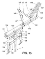
- an accessory (143) is observed constituted by a plane (144) with regulators (105), which accessory (143) increases the support surface in two dimensions, length and width, the regulators (105) being of double action or double extension in order to hold both flat and irregular pieces, whereby when a single trestle is used, a stable base will be available for pieces which are not very voluminous.
- the accessory includes underneath a guide (145) for mounting by sliding on supporting base (141) of the stand (134), and the guide (145) for which also has a transversal groove not represented, which will be in correspondence, in its assembly with the latch (142), to effect in this way a snap-fit between accessory and stand.
- FIG 15 another accessory (149) is shown with the corresponding lower guide (145), the notch (146) being seen in this case for engagement on the latch (142) of the supporting base (134), the accessory of this figure 15 being constituted by two elements (147) forming a "V", with roller (148) able to be blocked by means of the knob (148') for support and retention of elements having circular, oval, polygonal, etc. shape. These elements are mounted on the base (147') which has on its sides some notches (149') for mounting stabiliser bars.
- this accessory through its guide (145) is in a position to be mounted on the stand (134) which in turn is in a position to be mounted on the fishplate (4) of a bolster.
- the extendable arms of the bolster (36) can be rotary, both inclined to the right and left, and forward and backward, with respect to the fishplate (4) of the bolster (36) by means of a rotary mechanism defined between the ends of the main fishplate and the external tubes (153) of the extendable arms.
- Each rotary mechanism constitutes a first semi-circumferential plate (155') joined to the external tube (153), which plate hinges together with the latter with respect to a batten (201) on a screw (154'), which batten (201) in turn is joined perpendicularly to a second semi-circumferential plate (155) which hinges with respect to the fishplate (4) on a screw (154), it being foreseen that each of the semi-circumferential plates (155-155') be provided with an arched groove (156-156') in which a screw (157-157') sits which threads into a nut (159 " -159 ''') with a tightening washer (159-159') and manually operated knob (158-158') which allows the position of the first semi-circumferential plate (155') to be blocked with respect to the batten (201) regulating the forward or backward inclination of the external tube (153) with respect to the batten (201), as well as allowing the position of the second
- Another characteristic of the invention consists of the possibility of mounting an adaptable hoist on the bolster or bolsters of the trestle, for which it has been foreseen that the fishplates (4-4') of the different bolsters (34-35-36) have a hole (150) in the proximity of each of their ends which serve to house individual tubes (161) which are captured by means of some fastening sleeves (162), whereby those tubes (161) serve not only as base for mounting the hoist, but also add stiffness to the trestle assemblies.
- the hoist is mounted by means of some fastening angle bars (163) in a position which will later be secured by means of a lever (163'), the latter being connected with a spring (163 ") so that once the angle bars (163) are inserted they help said lever (163') to remain fixed in the hoist engagement system.
- the hoist is constituted by one vertical and two horizontal arms, a lower one and an upper one, whereby the latter is formed by a central and external tube (166) on which is mounted in a displaceable manner an internal tube (167) which carries a drive motor on one end (168) and some pulleys (169) on both ends, guiding a cable (170') with a fastening hook provided with a weight (170 "), whereby the displacement of the internal tube (167) allows the load to be gathered conveniently with respect to the bolster of the trestle.
- the displacement of the internal tube (167) with respect to the external tube (166) is carried out by means of bearings (170).
- the lower horizontal arm is formed by two tubes (165) and (165'), this last one is firmly attached to the tube (164) of the vertical arm and is inserted inside the tube (165), the extension between both being fixed by means of the knob (172').
- the vertical arm of said hoist is also formed by two tubes (164) and (164') which fit one inside the other and which regulate said hoist in height, whereby inside the internal tube (164'), a spring (171) is mounted with some pieces on its ends, being completed moreover with knobs (172) which secure both tubes (164) and (164') at the extension desired, namely the most appropriate.
- the two pieces foreseen on the ends of the spring (171) are those referred to with (173) and (174), this latter being joined to the base of the internal tube (164') and the upper one (173) abutting against a hoop (173') which is mounted on a rod (173 ") which is secured to the base of the external tube (164), whereby the result is that the spring (171) pulls the interior tube (164') upwards to facilitate the task of extending the arm.
- the telescopic column (100) is completed, as can be seen in figure 20 with a device of intermediate size, constituted from a sleeve (175) which is mounted on the lower tube (1) of the telescopic column (100), on which lower tube (1) a lower hoop (176) and an upper hoop (177) are foreseen, as well as corresponding screws worked by the locking knobs (125), represented in figures 8-12 and 20.
- a device of intermediate size constituted from a sleeve (175) which is mounted on the lower tube (1) of the telescopic column (100), on which lower tube (1) a lower hoop (176) and an upper hoop (177) are foreseen, as well as corresponding screws worked by the locking knobs (125), represented in figures 8-12 and 20.
- the sleeve (175) is positioned on the lower tube (1) hugging the hoop (176), while the hoop (177) abuts against another hoop (178) established for this purpose on the intermediate interior part of the sleeve (175), between said intermediate hoop (178) and the upper hoop (178') a tube (179) is mounted which has the same diameter as that which forms the lower tube (1) of the telescopic column (100), whereby that tube (179) is traversed by the setscrew (180) with its knob (180') which secures the position of the extendable tube, while the sleeve (175) is fixed and retained on the lower tube (1) by means of the setscrew (181) with its knob (181'), such sleeve (175) having an opening (182) in the longitudinal sense to permit the passage, in the sliding thereof over the lower tube (1), of the knobs (125) with their setscrews.
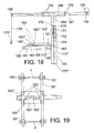
- a platform is shown with which the described trestle can be completed, the function of which platform is to facilitate work when a common and transportable surface is needed for one or more trestles, mainly when working with systems of elevation employing hydraulic, pneumatic or another feeding system which requires an associated equipment, which platform can moreover be moved by manual means or have an autonomous motor adapted to it to facilitate the task.
- the platform fundamentally has a lower base (183) with wheels (184) for its displacement, as well as adjustable stabilizers (185) for standing on the floor, which are locked when the platform has achieved its desired position and the stabilizers and regulators (185) of which are double action or extension and can be adjustable independently or jointly, in which second case it has been foreseen that in the upper part of the regulators (185) some pinions (186) are included over which a common chain (187) runs the displacement of which involves the rotation of all the pinions (186) and therefore the simultaneous regulation of all the stabilizers (185).
- This system described is used for flat floors with little irregularity, simplifying the anchoring of the platform, since with the operation of a regulator, through being mutually connected with the other regulators by means of a chain, all are stabilized at the same time, whereby for cases in which a more severe adaptation is required, the system of independent regulation will be used.
- the running wheels (184) can have two of them fixed and the other two able to swivel or have all of them able to swivel. These wheels can be replaced by ball systems.
- This platform is also completed with a second base joined to the lower part by means of some hinges or axles (193) in correspondence with one of the ends, while the opposite end will include some regulators (191) fitted with pinions (191') and common chain (191 ") which abuts on the lower base (183), and which when driven elevate that part of the adjustable base, referred to in general with the number (189).
- a third base (190) exists joined to the second by hinges or axles (194) in its longitudinal part, and other regulators (192) with pinions (192') and chain (192 ") to regulate and level the lateral position.
- the upper platform will be fitted with some plumb lines.
- the means of regulation (105) previously described can consist, as one observes in figure 22, of an interior regulator (196), terminating on the supporting base (106), which slides inside a sleeve (197), the position thereof being fixed by means of screw (198) operated by a knob (199).
Landscapes
- Engineering & Computer Science (AREA)
- General Engineering & Computer Science (AREA)
- Mechanical Engineering (AREA)
- Mutual Connection Of Rods And Tubes (AREA)
- Jib Cranes (AREA)
- Revetment (AREA)
- Holo Graphy (AREA)
- Tables And Desks Characterized By Structural Shape (AREA)
Applications Claiming Priority (4)
| Application Number | Priority Date | Filing Date | Title |
|---|---|---|---|
| ES200202784A ES2238123B1 (es) | 2002-12-04 | 2002-12-04 | Caballete multiuso. |
| ES200202784 | 2002-12-04 | ||
| ES200302762 | 2003-11-25 | ||
| ES200302762 | 2003-11-25 |
Publications (3)
| Publication Number | Publication Date |
|---|---|
| EP1450096A2 true EP1450096A2 (de) | 2004-08-25 |
| EP1450096A3 EP1450096A3 (de) | 2004-12-08 |
| EP1450096B1 EP1450096B1 (de) | 2007-08-22 |
Family
ID=32737459
Family Applications (1)
| Application Number | Title | Priority Date | Filing Date |
|---|---|---|---|
| EP03380283A Expired - Lifetime EP1450096B1 (de) | 2002-12-04 | 2003-12-04 | Mehrzweckbock |
Country Status (4)
| Country | Link |
|---|---|
| EP (1) | EP1450096B1 (de) |
| AT (1) | ATE371141T1 (de) |
| DE (1) | DE60315792D1 (de) |
| ES (1) | ES2295540T3 (de) |
Cited By (16)
| Publication number | Priority date | Publication date | Assignee | Title |
|---|---|---|---|---|
| CN105927826A (zh) * | 2016-06-16 | 2016-09-07 | 苏州华徕光电仪器有限公司 | 一种测绘仪器用支架 |
| CN107327161A (zh) * | 2017-08-10 | 2017-11-07 | 江苏旺材科技有限公司 | 一种卡扣式快拆独立支架 |
| CN107940201A (zh) * | 2017-12-24 | 2018-04-20 | 瀚科科技(大连)有限公司 | 一种防止摇晃的显示屏固定装置 |
| CN108930885A (zh) * | 2018-07-10 | 2018-12-04 | 广州番客信息科技有限公司 | 一种基于物联网的养殖监控装置 |
| CN109109732A (zh) * | 2018-10-24 | 2019-01-01 | 荣成恒力车业有限公司 | 一种房车外拓展篷 |
| CN110095479A (zh) * | 2019-02-20 | 2019-08-06 | 江苏能建机电实业集团有限公司 | 一种铝型材无损检测设备 |
| CN112404357A (zh) * | 2020-11-02 | 2021-02-26 | 丹东大王精铸有限公司 | 一种用于轻型建筑基础的结构及其加工方法 |
| CN113143111A (zh) * | 2020-01-07 | 2021-07-23 | 鸿富锦精密工业(武汉)有限公司 | 支撑装置 |
| CN113203008A (zh) * | 2021-04-29 | 2021-08-03 | 郜怀龙 | 一种用于跨断层水准测量的标尺支架 |
| CN113739031A (zh) * | 2021-09-15 | 2021-12-03 | 日照交通规划设计院有限公司 | 一种便于调节的高速公路监测支架 |
| CN114046303A (zh) * | 2021-11-25 | 2022-02-15 | 滁州市海正模具制造有限公司 | 一种管状结构快速连接件 |
| CN114060661A (zh) * | 2021-11-15 | 2022-02-18 | 安徽理工大学 | 一种建筑工程造价现场测绘装置 |
| CN114151662A (zh) * | 2021-12-07 | 2022-03-08 | 安博雷拉(深圳)智能科技有限公司 | 移动智能安全监察设备 |
| CN114440069A (zh) * | 2021-12-31 | 2022-05-06 | 浙江大学 | 一种自调节抛载式换能器阵列辅助机架 |
| CN114704724A (zh) * | 2022-03-30 | 2022-07-05 | 国网河北省电力有限公司沧州供电分公司 | 一种电网规划拓扑分析用辅助系统 |
| ES3018808A1 (es) * | 2023-11-15 | 2025-05-19 | Univ Jaen | Dispositivo adaptador para pértigas telescópicas |
Family Cites Families (4)
| Publication number | Priority date | Publication date | Assignee | Title |
|---|---|---|---|---|
| US5160125A (en) * | 1990-02-23 | 1992-11-03 | Jenkins Bobby L | Transmission utility stand |
| AUPO727597A0 (en) * | 1997-06-12 | 1997-07-03 | Lewin, George | A multi-purpose folding support stand for woodworking and other uses |
| US6273662B1 (en) * | 2000-08-31 | 2001-08-14 | Mark A. Fleckenstein | Lifting device |
| DE20208954U1 (de) * | 2002-06-06 | 2002-11-14 | Starkenberg, Werner, 33829 Borgholzhausen | Materialständer I., II., III. mit Zubehör |
-
2003
- 2003-12-04 AT AT03380283T patent/ATE371141T1/de not_active IP Right Cessation
- 2003-12-04 EP EP03380283A patent/EP1450096B1/de not_active Expired - Lifetime
- 2003-12-04 DE DE60315792T patent/DE60315792D1/de not_active Expired - Lifetime
- 2003-12-04 ES ES03380283T patent/ES2295540T3/es not_active Expired - Lifetime
Cited By (19)
| Publication number | Priority date | Publication date | Assignee | Title |
|---|---|---|---|---|
| CN105927826A (zh) * | 2016-06-16 | 2016-09-07 | 苏州华徕光电仪器有限公司 | 一种测绘仪器用支架 |
| CN107327161A (zh) * | 2017-08-10 | 2017-11-07 | 江苏旺材科技有限公司 | 一种卡扣式快拆独立支架 |
| CN107940201A (zh) * | 2017-12-24 | 2018-04-20 | 瀚科科技(大连)有限公司 | 一种防止摇晃的显示屏固定装置 |
| CN108930885A (zh) * | 2018-07-10 | 2018-12-04 | 广州番客信息科技有限公司 | 一种基于物联网的养殖监控装置 |
| CN109109732A (zh) * | 2018-10-24 | 2019-01-01 | 荣成恒力车业有限公司 | 一种房车外拓展篷 |
| CN110095479A (zh) * | 2019-02-20 | 2019-08-06 | 江苏能建机电实业集团有限公司 | 一种铝型材无损检测设备 |
| CN113143111B (zh) * | 2020-01-07 | 2023-12-01 | 鸿富锦精密工业(武汉)有限公司 | 支撑装置 |
| CN113143111A (zh) * | 2020-01-07 | 2021-07-23 | 鸿富锦精密工业(武汉)有限公司 | 支撑装置 |
| CN112404357A (zh) * | 2020-11-02 | 2021-02-26 | 丹东大王精铸有限公司 | 一种用于轻型建筑基础的结构及其加工方法 |
| CN113203008A (zh) * | 2021-04-29 | 2021-08-03 | 郜怀龙 | 一种用于跨断层水准测量的标尺支架 |
| CN113739031A (zh) * | 2021-09-15 | 2021-12-03 | 日照交通规划设计院有限公司 | 一种便于调节的高速公路监测支架 |
| CN114060661A (zh) * | 2021-11-15 | 2022-02-18 | 安徽理工大学 | 一种建筑工程造价现场测绘装置 |
| CN114046303A (zh) * | 2021-11-25 | 2022-02-15 | 滁州市海正模具制造有限公司 | 一种管状结构快速连接件 |
| CN114046303B (zh) * | 2021-11-25 | 2023-07-25 | 常州源光节能科技有限公司 | 一种管状结构快速连接件 |
| CN114151662A (zh) * | 2021-12-07 | 2022-03-08 | 安博雷拉(深圳)智能科技有限公司 | 移动智能安全监察设备 |
| CN114440069A (zh) * | 2021-12-31 | 2022-05-06 | 浙江大学 | 一种自调节抛载式换能器阵列辅助机架 |
| CN114704724A (zh) * | 2022-03-30 | 2022-07-05 | 国网河北省电力有限公司沧州供电分公司 | 一种电网规划拓扑分析用辅助系统 |
| CN114704724B (zh) * | 2022-03-30 | 2024-04-09 | 国网河北省电力有限公司沧州供电分公司 | 一种电网规划拓扑分析用辅助系统 |
| ES3018808A1 (es) * | 2023-11-15 | 2025-05-19 | Univ Jaen | Dispositivo adaptador para pértigas telescópicas |
Also Published As
| Publication number | Publication date |
|---|---|
| EP1450096A3 (de) | 2004-12-08 |
| ES2295540T3 (es) | 2008-04-16 |
| ATE371141T1 (de) | 2007-09-15 |
| EP1450096B1 (de) | 2007-08-22 |
| DE60315792D1 (de) | 2007-10-04 |
Similar Documents
| Publication | Publication Date | Title |
|---|---|---|
| EP1450096B1 (de) | Mehrzweckbock | |
| US11161718B2 (en) | Lifting and transporting system | |
| US9694936B2 (en) | Lifting and transporting system | |
| US3957137A (en) | Portable material lift | |
| US4050671A (en) | Door hanger device | |
| US3752261A (en) | Multi-stage lift | |
| US6341788B1 (en) | Hand truck | |
| US5772183A (en) | Portable lifting apparatus for demountable positioning in an overhead location | |
| USRE33645E (en) | Foldable machinist's tool tray | |
| US4479634A (en) | Jackable prop | |
| US5368126A (en) | Adjustable work platform | |
| US4691904A (en) | Automatic or standard transmission handling device | |
| EP0690764A1 (de) | Transporteinrichtung für kraftfahrzeuge und kraftfahrzeugteile | |
| US20030024604A1 (en) | Portable work bench with an extension assembly having a workpiece support assembly and work stop assembly thereon | |
| US8662252B2 (en) | Leveling system for portable work platforms | |
| US20180238111A1 (en) | An extendable work platform | |
| US6345807B1 (en) | Small vehicle lift | |
| US20210139096A1 (en) | Lift assembly for a vehicle | |
| US20120234629A1 (en) | Support Platform | |
| US4779878A (en) | Trolley base with height adjuster | |
| JPH08324729A (ja) | 重量物搬送具 | |
| AU2014204487A1 (en) | Mobile support device | |
| JPH07251903A (ja) | 昇降装置 | |
| US10196250B2 (en) | Bi-pod rescue strut system | |
| US4886139A (en) | Mobile scaffold with power-operated platform elevation |
Legal Events
| Date | Code | Title | Description |
|---|---|---|---|
| PUAI | Public reference made under article 153(3) epc to a published international application that has entered the european phase |
Free format text: ORIGINAL CODE: 0009012 |
|
| AK | Designated contracting states |
Kind code of ref document: A2 Designated state(s): AT BE BG CH CY CZ DE DK EE ES FI FR GB GR HU IE IT LI LU MC NL PT RO SE SI SK TR |
|
| AX | Request for extension of the european patent |
Extension state: AL LT LV MK |
|
| PUAL | Search report despatched |
Free format text: ORIGINAL CODE: 0009013 |
|
| AK | Designated contracting states |
Kind code of ref document: A3 Designated state(s): AT BE BG CH CY CZ DE DK EE ES FI FR GB GR HU IE IT LI LU MC NL PT RO SE SI SK TR |
|
| AX | Request for extension of the european patent |
Extension state: AL LT LV MK |
|
| 17P | Request for examination filed |
Effective date: 20050607 |
|
| AKX | Designation fees paid |
Designated state(s): AT BE BG CH CY CZ DE DK EE ES FI FR GB GR HU IE IT LI LU MC NL PT RO SE SI SK TR |
|
| GRAP | Despatch of communication of intention to grant a patent |
Free format text: ORIGINAL CODE: EPIDOSNIGR1 |
|
| GRAS | Grant fee paid |
Free format text: ORIGINAL CODE: EPIDOSNIGR3 |
|
| GRAA | (expected) grant |
Free format text: ORIGINAL CODE: 0009210 |
|
| AK | Designated contracting states |
Kind code of ref document: B1 Designated state(s): AT BE BG CH CY CZ DE DK EE ES FI FR GB GR HU IE IT LI LU MC NL PT RO SE SI SK TR |
|
| REG | Reference to a national code |
Ref country code: GB Ref legal event code: FG4D |
|
| REG | Reference to a national code |
Ref country code: CH Ref legal event code: EP |
|
| REG | Reference to a national code |
Ref country code: IE Ref legal event code: FG4D |
|
| REF | Corresponds to: |
Ref document number: 60315792 Country of ref document: DE Date of ref document: 20071004 Kind code of ref document: P |
|
| PG25 | Lapsed in a contracting state [announced via postgrant information from national office to epo] |
Ref country code: NL Free format text: LAPSE BECAUSE OF FAILURE TO SUBMIT A TRANSLATION OF THE DESCRIPTION OR TO PAY THE FEE WITHIN THE PRESCRIBED TIME-LIMIT Effective date: 20070822 Ref country code: FI Free format text: LAPSE BECAUSE OF FAILURE TO SUBMIT A TRANSLATION OF THE DESCRIPTION OR TO PAY THE FEE WITHIN THE PRESCRIBED TIME-LIMIT Effective date: 20070822 Ref country code: BG Free format text: LAPSE BECAUSE OF FAILURE TO SUBMIT A TRANSLATION OF THE DESCRIPTION OR TO PAY THE FEE WITHIN THE PRESCRIBED TIME-LIMIT Effective date: 20071122 |
|
| NLV1 | Nl: lapsed or annulled due to failure to fulfill the requirements of art. 29p and 29m of the patents act | ||
| PG25 | Lapsed in a contracting state [announced via postgrant information from national office to epo] |
Ref country code: AT Free format text: LAPSE BECAUSE OF FAILURE TO SUBMIT A TRANSLATION OF THE DESCRIPTION OR TO PAY THE FEE WITHIN THE PRESCRIBED TIME-LIMIT Effective date: 20070822 Ref country code: LI Free format text: LAPSE BECAUSE OF FAILURE TO SUBMIT A TRANSLATION OF THE DESCRIPTION OR TO PAY THE FEE WITHIN THE PRESCRIBED TIME-LIMIT Effective date: 20070822 Ref country code: CH Free format text: LAPSE BECAUSE OF FAILURE TO SUBMIT A TRANSLATION OF THE DESCRIPTION OR TO PAY THE FEE WITHIN THE PRESCRIBED TIME-LIMIT Effective date: 20070822 |
|
| REG | Reference to a national code |
Ref country code: CH Ref legal event code: PL |
|
| PG25 | Lapsed in a contracting state [announced via postgrant information from national office to epo] |
Ref country code: BE Free format text: LAPSE BECAUSE OF FAILURE TO SUBMIT A TRANSLATION OF THE DESCRIPTION OR TO PAY THE FEE WITHIN THE PRESCRIBED TIME-LIMIT Effective date: 20070822 |
|
| REG | Reference to a national code |
Ref country code: ES Ref legal event code: FG2A Ref document number: 2295540 Country of ref document: ES Kind code of ref document: T3 |
|
| ET | Fr: translation filed | ||
| PG25 | Lapsed in a contracting state [announced via postgrant information from national office to epo] |
Ref country code: GR Free format text: LAPSE BECAUSE OF FAILURE TO SUBMIT A TRANSLATION OF THE DESCRIPTION OR TO PAY THE FEE WITHIN THE PRESCRIBED TIME-LIMIT Effective date: 20071123 Ref country code: DK Free format text: LAPSE BECAUSE OF FAILURE TO SUBMIT A TRANSLATION OF THE DESCRIPTION OR TO PAY THE FEE WITHIN THE PRESCRIBED TIME-LIMIT Effective date: 20070822 |
|
| PG25 | Lapsed in a contracting state [announced via postgrant information from national office to epo] |
Ref country code: SK Free format text: LAPSE BECAUSE OF FAILURE TO SUBMIT A TRANSLATION OF THE DESCRIPTION OR TO PAY THE FEE WITHIN THE PRESCRIBED TIME-LIMIT Effective date: 20070822 Ref country code: CZ Free format text: LAPSE BECAUSE OF FAILURE TO SUBMIT A TRANSLATION OF THE DESCRIPTION OR TO PAY THE FEE WITHIN THE PRESCRIBED TIME-LIMIT Effective date: 20070822 Ref country code: PT Free format text: LAPSE BECAUSE OF FAILURE TO SUBMIT A TRANSLATION OF THE DESCRIPTION OR TO PAY THE FEE WITHIN THE PRESCRIBED TIME-LIMIT Effective date: 20080122 |
|
| PLBE | No opposition filed within time limit |
Free format text: ORIGINAL CODE: 0009261 |
|
| STAA | Information on the status of an ep patent application or granted ep patent |
Free format text: STATUS: NO OPPOSITION FILED WITHIN TIME LIMIT |
|
| PG25 | Lapsed in a contracting state [announced via postgrant information from national office to epo] |
Ref country code: RO Free format text: LAPSE BECAUSE OF FAILURE TO SUBMIT A TRANSLATION OF THE DESCRIPTION OR TO PAY THE FEE WITHIN THE PRESCRIBED TIME-LIMIT Effective date: 20070822 Ref country code: SE Free format text: LAPSE BECAUSE OF FAILURE TO SUBMIT A TRANSLATION OF THE DESCRIPTION OR TO PAY THE FEE WITHIN THE PRESCRIBED TIME-LIMIT Effective date: 20071122 |
|
| 26N | No opposition filed |
Effective date: 20080526 |
|
| PG25 | Lapsed in a contracting state [announced via postgrant information from national office to epo] |
Ref country code: MC Free format text: LAPSE BECAUSE OF NON-PAYMENT OF DUE FEES Effective date: 20071231 Ref country code: DE Free format text: LAPSE BECAUSE OF FAILURE TO SUBMIT A TRANSLATION OF THE DESCRIPTION OR TO PAY THE FEE WITHIN THE PRESCRIBED TIME-LIMIT Effective date: 20071123 |
|
| GBPC | Gb: european patent ceased through non-payment of renewal fee |
Effective date: 20071204 |
|
| PG25 | Lapsed in a contracting state [announced via postgrant information from national office to epo] |
Ref country code: IE Free format text: LAPSE BECAUSE OF NON-PAYMENT OF DUE FEES Effective date: 20071204 |
|
| PG25 | Lapsed in a contracting state [announced via postgrant information from national office to epo] |
Ref country code: GB Free format text: LAPSE BECAUSE OF NON-PAYMENT OF DUE FEES Effective date: 20071204 |
|
| PG25 | Lapsed in a contracting state [announced via postgrant information from national office to epo] |
Ref country code: EE Free format text: LAPSE BECAUSE OF FAILURE TO SUBMIT A TRANSLATION OF THE DESCRIPTION OR TO PAY THE FEE WITHIN THE PRESCRIBED TIME-LIMIT Effective date: 20070822 |
|
| PG25 | Lapsed in a contracting state [announced via postgrant information from national office to epo] |
Ref country code: SI Free format text: LAPSE BECAUSE OF FAILURE TO SUBMIT A TRANSLATION OF THE DESCRIPTION OR TO PAY THE FEE WITHIN THE PRESCRIBED TIME-LIMIT Effective date: 20070822 |
|
| PG25 | Lapsed in a contracting state [announced via postgrant information from national office to epo] |
Ref country code: CY Free format text: LAPSE BECAUSE OF FAILURE TO SUBMIT A TRANSLATION OF THE DESCRIPTION OR TO PAY THE FEE WITHIN THE PRESCRIBED TIME-LIMIT Effective date: 20070822 |
|
| PG25 | Lapsed in a contracting state [announced via postgrant information from national office to epo] |
Ref country code: LU Free format text: LAPSE BECAUSE OF NON-PAYMENT OF DUE FEES Effective date: 20071204 |
|
| PG25 | Lapsed in a contracting state [announced via postgrant information from national office to epo] |
Ref country code: HU Free format text: LAPSE BECAUSE OF FAILURE TO SUBMIT A TRANSLATION OF THE DESCRIPTION OR TO PAY THE FEE WITHIN THE PRESCRIBED TIME-LIMIT Effective date: 20080223 Ref country code: TR Free format text: LAPSE BECAUSE OF FAILURE TO SUBMIT A TRANSLATION OF THE DESCRIPTION OR TO PAY THE FEE WITHIN THE PRESCRIBED TIME-LIMIT Effective date: 20070822 |
|
| PGFP | Annual fee paid to national office [announced via postgrant information from national office to epo] |
Ref country code: FR Payment date: 20081215 Year of fee payment: 6 |
|
| PG25 | Lapsed in a contracting state [announced via postgrant information from national office to epo] |
Ref country code: FR Free format text: LAPSE BECAUSE OF NON-PAYMENT OF DUE FEES Effective date: 20091231 |
|
| PG25 | Lapsed in a contracting state [announced via postgrant information from national office to epo] |
Ref country code: IT Free format text: LAPSE BECAUSE OF NON-PAYMENT OF DUE FEES Effective date: 20071231 |
|
| REG | Reference to a national code |
Ref country code: FR Ref legal event code: ST Effective date: 20110826 |
|
| PGFP | Annual fee paid to national office [announced via postgrant information from national office to epo] |
Ref country code: ES Payment date: 20121204 Year of fee payment: 10 |
|
| REG | Reference to a national code |
Ref country code: ES Ref legal event code: FD2A Effective date: 20150709 |
|
| PG25 | Lapsed in a contracting state [announced via postgrant information from national office to epo] |
Ref country code: ES Free format text: LAPSE BECAUSE OF NON-PAYMENT OF DUE FEES Effective date: 20131205 |