EP1450192A1 - Fibre optique plastique et cable a fibres optiques - Google Patents
Fibre optique plastique et cable a fibres optiques Download PDFInfo
- Publication number
- EP1450192A1 EP1450192A1 EP02788690A EP02788690A EP1450192A1 EP 1450192 A1 EP1450192 A1 EP 1450192A1 EP 02788690 A EP02788690 A EP 02788690A EP 02788690 A EP02788690 A EP 02788690A EP 1450192 A1 EP1450192 A1 EP 1450192A1
- Authority
- EP
- European Patent Office
- Prior art keywords
- light
- optical fiber
- plastic optical
- protection coating
- core
- Prior art date
- Legal status (The legal status is an assumption and is not a legal conclusion. Google has not performed a legal analysis and makes no representation as to the accuracy of the status listed.)
- Withdrawn
Links
Images

Classifications
-
- G—PHYSICS
- G02—OPTICS
- G02B—OPTICAL ELEMENTS, SYSTEMS OR APPARATUS
- G02B6/00—Light guides; Structural details of arrangements comprising light guides and other optical elements, e.g. couplings
-
- G—PHYSICS
- G02—OPTICS
- G02B—OPTICAL ELEMENTS, SYSTEMS OR APPARATUS
- G02B6/00—Light guides; Structural details of arrangements comprising light guides and other optical elements, e.g. couplings
- G02B6/02—Optical fibres with cladding with or without a coating
- G02B6/02033—Core or cladding made from organic material, e.g. polymeric material
-
- G—PHYSICS
- G02—OPTICS
- G02B—OPTICAL ELEMENTS, SYSTEMS OR APPARATUS
- G02B6/00—Light guides; Structural details of arrangements comprising light guides and other optical elements, e.g. couplings
- G02B6/44—Mechanical structures for providing tensile strength and external protection for fibres, e.g. optical transmission cables
- G02B6/4401—Optical cables
- G02B6/4429—Means specially adapted for strengthening or protecting the cables
- G02B6/443—Protective covering
-
- G—PHYSICS
- G02—OPTICS
- G02B—OPTICAL ELEMENTS, SYSTEMS OR APPARATUS
- G02B6/00—Light guides; Structural details of arrangements comprising light guides and other optical elements, e.g. couplings
- G02B6/44—Mechanical structures for providing tensile strength and external protection for fibres, e.g. optical transmission cables
- G02B6/4401—Optical cables
- G02B6/4402—Optical cables with one single optical waveguide
-
- G—PHYSICS
- G02—OPTICS
- G02B—OPTICAL ELEMENTS, SYSTEMS OR APPARATUS
- G02B6/00—Light guides; Structural details of arrangements comprising light guides and other optical elements, e.g. couplings
- G02B6/44—Mechanical structures for providing tensile strength and external protection for fibres, e.g. optical transmission cables
- G02B6/4479—Manufacturing methods of optical cables
- G02B6/4482—Code or colour marking
Definitions
- the present invention relates to a plastic optical fiber formed by employing a resin for a core and a cladding, and to an optical fiber cable.
- fluoropolymer plastic optical fibers which employ a fluorine-containing resin for a core 101 and a cladding 102 shown in Fig. 4, for example, and which are suitable for using a near-infrared light.
- a plastic optical fiber having a grated index type refractive index distribution of the core which can achieve a transmission rate of at least 100 Mbps between two points aparting at least 100 m from each other.
- plastic optical fiber of this type which comprises a protection coating 103 (refer to Fig. 4) employing a hydrocarbon type resin provided on the outer periphery of the cladding 102, for reinforcement.
- a protection coating 103 (refer to Fig. 4) employing a hydrocarbon type resin provided on the outer periphery of the cladding 102, for reinforcement.
- NA numerical aperture
- a focusing lens is employed when a LD (laser diode) or a LED (light emitting diode) is employed as a light source for an optical link.
- a LD laser diode
- LED light emitting diode
- the focusing lens is not employed for reducing the cost, light emitted from the LD or the LED may spread before it is incident into the optical fiber, and is incident also into the protection coating 103 besides the core 101. In this case, there is a possibility that the light propagating in the protection coating 103 causes a problem such as deterioration of a receiving signal at the destination.
- the light is absorbed by hydrocarbon resin in the protection coating 103. Accordingly, when the light is transmitted with a length of at least 10 m, the light transmitted through the protection coating 103 is not observed at the destination.
- the absorption phenomenon by the hydrocarbon resin is not likely to occur, and the light transmitted in the protection coating 103 is observed at the destination in some cases.
- pulses of light propagating in the protection coating 103 reach a photo-detector system at the destination in some cases if the transmission length is short e.g. a few meters.
- the protection coating 103 has a higher refractive index than the core 101, the speed of light propagating in the protection coating 103 is slower than that in the core 101. Therefore, the light propagating in the protection coating 103 propagates slower than the light propagating in the core 101, and they are observed as two separated pulses at the photo-detector unit. As a result, there occurs a problem that bit error is increased to deteriorate the quality of digital communication.
- the present invention provides a plastic optical fiber comprising a core and a cladding each made of a resin containing an appropriate material, and a protection coating made of a hydrocarbon type resin formed on the outer periphery of the cladding, wherein an absorption layer containing a dye for absorbing light of a specific wavelength or light in a specific wavelength range is formed on the outermost portion of the protection coating.
- the present invention provides the above-mentioned plastic optical fiber, wherein the core and the cladding are each made of a fluorine-containing resin.
- the present invention provides the plastic optical fiber, wherein the absorption layer is constituted to absorb at least light, incident into the absorption layer from outside, having the same wavelength as the light to be propagated in the core, by the effect of the dye so that the light is prevented from entering into the core and the cladding.
- the present invention provides any one of the above-mentioned plastic optical fibers wherein the absorption layer is formed by coating.
- the present invention provides the plastic optical fiber wherein a pigment employing an inorganic material, a pigment employing an organic material or a pigment as a mixture of these pigments, is employed as the dye.
- the present invention provides an optical fiber cable comprising any one of the above-mentioned plastic optical fibers.
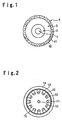
- Fig. 1 is a cross-sectional schematic view showing the construction of a fluoropolymer plastic optical fiber according to an embodiment of the present invention.
- the fluoropolymer plastic optical fiber of this embodiment comprises a core 1, a cladding 2, a protection coating 3 and a colored layer 4 in this order from the center.
- the colored layer 4 contains in its base material 41 a blue dye 42.
- the core 1 of this embodiment is formed, for example, by a preforming method (or an extrusion method) and subjected to e.g. a thermal diffusion method to have a GI (grated index) construction having a refractive index of 1.355 at the center and a refractive index distribution close to a Gaussian distribution.
- the refractive index distribution of the core 1 may be a SI (step index) type as well.
- the light dispersion in core and cladding materials can be reduced because the core 1 and the cladding 2 contain fluorine as described above. Specifically, it has less light dispersion from a visible region to a near infrared region as compared with other plastic optical fibers such as an optical fiber made of PMMA, and has less light dispersion in the visible region as compared with silica optical fibers. Such reduction of light dispersion becomes more remarkable by doping a perfluoro compound into the core 1.
- the protection coating 3 is made of a material in which the fluorine content is positively excluded so that it can absorb a (near) infrared light.
- it is made of a resin without containing fluorine such as polymethyl methacrylate (PMMA) having a refractive index of, for example, 1.492 and is formed to have a thickness of 246 ⁇ m (outer diameter: 492 ⁇ m).
- PMMA polymethyl methacrylate
- the refractive index of this protection coating 3 is higher than that of the core 1 and the cladding 2 in this embodiment.
- the opposite construction is also acceptable.
- the absorption layer 4 is constituted so that at least light incident into the absorption layer 4 from the outside, the light having the same wavelength as the light propagating in the core 1, is absorbed by a dye 42 to be described later, and the incident light from the side of the absorption layer 4 is prevented from entering into the core 1 and the cladding 2.
- a material having higher refractive index than the protection coating 3 is employed for the base material 41 in this absorption layer 4, and the absorption layer 4 is formed to have a thickness of, for example, about 7 ⁇ m.
- a UV-curable epoxy acrylate having a refractive index of 1.548 is employed as the base material 41 in this embodiment, and it is formed by a pressure dice.
- the absorption layer 4 is formed to contain the dye 42 of a color, for example, blue in this embodiment, which can absorb external light having the same wavelength as the wavelength of light to be transmitted in the core 1, in order to prevent light having such a wavelength from entering into the core 1 and the cladding 2 by absorbing the light even if the light is incident from the outside.
- the dye 42 of this embodiment is constituted by an appropriate inorganic material (such as TiO 2 ZnO or 2PbCO 3 ) as a white pigment and an appropriate organic material (such as a phthalocyanine, a dioxadine or an anthraquinone) as a blue pigment mixed in the inorganic material.
- an appropriate inorganic material such as TiO 2 ZnO or 2PbCO 3
- an appropriate organic material such as a phthalocyanine, a dioxadine or an anthraquinone
- the mixing ratio is not limited to this ratio.
- the absorption layer 4 is formed by coating the outer periphery of the protection coating 3, and an UV-curable resin is employed for the base material 41 and the resin is UV-cured to increase the bond strength in this embodiment.
- an UV-curable resin is employed for the base material 41 and the resin is UV-cured to increase the bond strength in this embodiment.
- a thermosetting resin may be employed for the base material 41 and cured by heat.
- a UV-curable resin is preferred for the base material 41 from a viewpoint of productivity.
- the refractive index of the base material 41 There is no particular restriction as to the refractive index of the base material 41.
- the dye 42 is mixed in the absorption layer 4, even if light is incident from the outside and transmitted through the fluoropolymer plastic optical fiber, at least external light having the same wavelength as the signal light transmitted in the core 1 can be absorbed when it collide with the dye 42 during its transmission in the absorption layer 4. As a result, it is possible to prevent the light from entering into the core 1 in the fluoropolymer plastic optical fiber.
- the absorption effect is obtainable in the wavelength region of from 500 to 1300 nm.
- the present invention further provides an optical fiber cable comprising the above-mentioned fluoropolymer plastic optical fiber.
- an optical fiber cable comprising the above-mentioned fluoropolymer plastic optical fiber.
- the optical fiber cable shown in Fig. 2 has a tension member 10 at the center and the fluoropolymer plastic optical fiber 20 as mentioned above is accommodated in each of slots 11 of a slot rod 12 in which a plurality of slots 11 are formed at the outer periphery at equal intervals. Then, the outer periphery is wrapped with a wrapping tape 13 and the entirety is wrapped with a sheath 14.
- a reference numeral 15 in the Figure designates a tearing string for easily removing the sheath 14 so as to take out the fluoropolymer plastic optical fibers 20 from the cable at a time of branching.
- the Figure shows a construction of twelve fibers in which all twelve fluoropolymer plastic optical fibers 20 are accommodated. However, the numbers of the slots 11 and the fluoropolymer plastic optical fibers 20 can be optionally selected.
- a plurality (four in this embodiment) of the above-mentioned fluoropolymer plastic optical fibers 20 can be accommodated in each slot 11.
- the plurality of fluoropolymer plastic optical fibers 20 may be coated as a whole to prevent the fluoropolymer plastic optical fibers 20 from colliding with each other by e.g. vibration.
- the cable may be flattened as described in e.g. JP-A-11-231181 not shown. Further, a plurality of flattened cables may be laminated as described in e.g. JP-A-11-202171.
- the refractive index of the resin to be employed as the base material 41 of the colored layer 4 there is no restriction as to the refractive index of the resin to be employed as the base material 41 of the colored layer 4, and it may, for example, be higher or lower than the refractive index of the protection coating 3 (the refractive index of the colored layer 4 is higher in this embodiment). Each of these cases will be described.
- a protection coating made of polymethyl methacrylate (PMMA) was provided on this bare fiber.
- the plastic optical fiber B of the present invention one comprising the same core 1, cladding 2 and protection coating 3 as those of the plastic optical fiber A of the Comparative Example, was employed. Further, on the outer periphery of the protection coating 3, an absorption layer 4 for which UV-curable epoxy acrylate was used as the base material 41 and a blue dye was incorporated therein, was formed to be 7 ⁇ m thick by appropriately controlling the line speed and the UV radiation intensity so that the heat amount provided by a known UV radiation apparatus became less than the softening heat amount of the plastic optical fiber B.
- the core diameters, the cladding diameters and the protection coating diameters of these optical fibers A and B were each equal to each other and they were 120 ⁇ m, 230 ⁇ m and 492 ⁇ m respectively.
- incident-side end faces of these optical fibers A and B were fixed to an optical stage, so that the pulses could be incident at various positions of the incident-side end faces by finely adjusting the optical stage.
- Pulse waves from output-side end faces of these plastic optical fibers A and B were observed by a sampling optical oscilloscope OOS-01 manufactured by Hamamatsu Photonics K.K.
- a plastic optical fiber C was prepared, the fiber comprising a core 1, a cladding 2 and a protection coating 3 each being the same as those of the plastic optical fiber of the Comparative Example in "Example 1", and an absorption layer 4 formed on the outer periphery of the protection coating 3, made of a UV-curable epoxy acrylate as a base material 41 containing carbon black as an inorganic pigment, the absorption layer being formed to be 7 ⁇ m thick by properly controlling the line speed and the UV radiation intensity so that heat amount provided by a known UV radiation apparatus becomes less than the softening heat amount of the plastic optical fiber A.
- the core diameter, the cladding diameter and the protection coating diameter of the plastic optical fiber C were the same as those of the plastic optical fibers A and B, and they were 120 ⁇ m, 230 ⁇ m and 492 ⁇ m respectively. There was observed no pulse propagating in the protection coating in the plastic optical fiber C like the one in the plastic optical fiber A.
- the cable has a diameter of 11.5 mm, and has a tension member 10 made of a blueing steel wire having a diameter of 1.6 mm at the center of the cable.
- the plastic optical fiber B prepared in "Example 1" is accommodated in each slot 11 of a slot rod 12 made of polyethylene which has twelve slots 11 formed at equal intervals at its periphery.
- a wrapping tape 13 made of polyester of 30 mm wide and 0.18 mm thick is wrapped three times around the slot rod 12, and it is entirely covered with a sheath 14 made of a non-flammable polyethylene having a thickness of 1.0 mm.
- a tearing string 15 is made of a para-type all aromatic polyamide fiber of 1000 denier.
- the present invention provides a plastic optical fiber comprising a core and a cladding each made of a resin containing an appropriate material, and a protection coating made of a hydrocarbon type resin formed on the outer periphery of the cladding, wherein an absorption layer containing a dye for absorbing light of a specific wavelength or light in a specific wavelength range formed as the outermost layer of the protection coating, whereby it becomes possible to prevent light from propagating in the protection coating which may create a problem when the fiber of a short distance is used for an optical transmission at a high bit rate, and to prevent transmission errors from occurring.
- an expensive package of LD or LED with a lens which has been used for focusing output light from the light source at the core of a plastic optical fiber, or an external lens which has been required besides the light source. become unnecessary.
- the problem that the signal light is propagated in the protection coating can be prevented from occurring, whereby it becomes possible to reduce the cost of a transmission apparatus.
- an absorption layer is provided as the outermost layer of the plastic optical fiber, whereby even if light of the same wavelength as signal light propagating in the core of the plastic optical fiber is incident from the outside, such light is absorbed by a dye in the absorption layer and is prevented from entering into the core to disturb the signal light. Accordingly, high quality optical communication becomes possible.
- the present invention it becomes possible to prevent deterioration of the protection coating due to UV rays contained in the sun light or light from fluorescent lamps even if a plastic optical fiber is laid out without being covered e.g. in a cable.
- each plastic optical fiber can be easily identified in a case where many plastic fibers are used as a group, whereby various types of works can be performed efficiently to the group of plastic optical fibers.
- the optical fiber cable of the present invention comprises fluoropolymer plastic optical fibers having the above-mentioned characteristics, whereby even in a case of not employing a lens as a combination for focusing light or in a case of using visible light or using an infrared light in a short communication distance, unnecessary propagation light can be removed and high quality optical communication can be performed.
Landscapes
- Physics & Mathematics (AREA)
- General Physics & Mathematics (AREA)
- Optics & Photonics (AREA)
- Optical Fibers, Optical Fiber Cores, And Optical Fiber Bundles (AREA)
Applications Claiming Priority (5)
| Application Number | Priority Date | Filing Date | Title |
|---|---|---|---|
| JP2001366371 | 2001-11-30 | ||
| JP2001366371 | 2001-11-30 | ||
| JP2002329656A JP2003227976A (ja) | 2001-11-30 | 2002-11-13 | プラスチック光ファイバおよび光ファイバケーブル |
| JP2002329656 | 2002-11-13 | ||
| PCT/JP2002/012517 WO2003046631A1 (fr) | 2001-11-30 | 2002-11-29 | Fibre optique plastique et cable a fibres optiques |
Publications (2)
| Publication Number | Publication Date |
|---|---|
| EP1450192A1 true EP1450192A1 (fr) | 2004-08-25 |
| EP1450192A4 EP1450192A4 (fr) | 2005-08-31 |
Family
ID=26624788
Family Applications (1)
| Application Number | Title | Priority Date | Filing Date |
|---|---|---|---|
| EP02788690A Withdrawn EP1450192A4 (fr) | 2001-11-30 | 2002-11-29 | Fibre optique plastique et cable a fibres optiques |
Country Status (8)
| Country | Link |
|---|---|
| US (1) | US20040218851A1 (fr) |
| EP (1) | EP1450192A4 (fr) |
| JP (1) | JP2003227976A (fr) |
| KR (1) | KR20040053149A (fr) |
| CN (1) | CN1592862A (fr) |
| AU (1) | AU2002355057A1 (fr) |
| TW (1) | TWI256494B (fr) |
| WO (1) | WO2003046631A1 (fr) |
Cited By (1)
| Publication number | Priority date | Publication date | Assignee | Title |
|---|---|---|---|---|
| WO2008012328A1 (fr) * | 2006-07-27 | 2008-01-31 | Continental Automotive Gmbh | Bande de fibres pour capteur à fibres optiques |
Families Citing this family (17)
| Publication number | Priority date | Publication date | Assignee | Title |
|---|---|---|---|---|
| CN100538420C (zh) * | 2005-05-09 | 2009-09-09 | 三菱丽阳株式会社 | 塑料光纤电缆 |
| JP4728132B2 (ja) * | 2006-02-01 | 2011-07-20 | 日本電信電話株式会社 | 光コード |
| KR101035123B1 (ko) * | 2007-02-02 | 2011-05-19 | 황임규 | 플라스틱 광섬유를 내장한 실리콘 고무 고형체 및 그제조방법 |
| JP5176393B2 (ja) * | 2007-05-25 | 2013-04-03 | 富士ゼロックス株式会社 | 高分子フィルム光導波路の製造方法 |
| JP2009075362A (ja) * | 2007-09-20 | 2009-04-09 | Fuji Xerox Co Ltd | 光導波路及びその製造方法 |
| JP4657327B2 (ja) | 2008-07-17 | 2011-03-23 | 三菱電線工業株式会社 | 光ファイバ心線へのコネクタの固定構造 |
| WO2010113639A1 (fr) * | 2009-03-31 | 2010-10-07 | 東レ株式会社 | Fibre optique en matière plastique et code de fibre optique en matière plastique |
| US20140093690A1 (en) * | 2011-05-31 | 2014-04-03 | Nanoptics, Incorporated | Method and apparatus for lithographic manufacture of multi-component polymeric fiber plates |
| JP2017142285A (ja) * | 2016-02-08 | 2017-08-17 | 住友電気工業株式会社 | 光ファイバケーブル |
| JP6312760B2 (ja) * | 2016-08-30 | 2018-04-18 | 株式会社フジクラ | 光ファイバ |
| WO2018066596A1 (fr) * | 2016-10-04 | 2018-04-12 | 住友電気工業株式会社 | Tige de fente et câble à fibre optique |
| JP2018062448A (ja) * | 2016-10-13 | 2018-04-19 | 住友電気工業株式会社 | 光ファイバ心線の製造方法、および光ファイバ心線 |
| US10605984B2 (en) | 2016-12-01 | 2020-03-31 | Waymo Llc | Array of waveguide diffusers for light detection using an aperture |
| JP2019049658A (ja) * | 2017-09-11 | 2019-03-28 | 小池 康博 | 光ファイバケーブル |
| CN110231677B (zh) * | 2019-06-06 | 2020-12-18 | 中国建筑材料科学研究总院有限公司 | 微透镜阵列及其制备方法 |
| CN114514455B (zh) | 2019-09-30 | 2024-12-24 | 日东电工株式会社 | 塑料光纤 |
| WO2023189998A1 (fr) | 2022-03-31 | 2023-10-05 | 東レ株式会社 | Fibre optique en plastique et dispositif de capteur médical |
Family Cites Families (10)
| Publication number | Priority date | Publication date | Assignee | Title |
|---|---|---|---|---|
| DE2560000C2 (de) * | 1974-03-20 | 1984-09-20 | Sumitomo Electric Industries, Ltd., Osaka | Optische Lichtleitfaser |
| JPS5893003A (ja) * | 1981-11-27 | 1983-06-02 | Mitsubishi Rayon Co Ltd | 光伝送性繊維 |
| JPS59228205A (ja) * | 1983-06-09 | 1984-12-21 | Sumitomo Electric Ind Ltd | 溝付き光伝送路 |
| JPS62109004A (ja) * | 1985-11-08 | 1987-05-20 | Hitachi Ltd | プラスチツク光フアイバ、その製法及び樹脂 |
| JP2907544B2 (ja) * | 1989-05-12 | 1999-06-21 | ディーエスエム ナムローゼ フェンノートシャップ | 光硬化性着色二次光ファイバー被覆 |
| CA2056469C (fr) * | 1990-11-30 | 1997-03-25 | Hiroaki Oonishi | Fibres optiques en plastique |
| JPH0739004U (ja) * | 1993-12-25 | 1995-07-14 | 住友電気工業株式会社 | 光ファイバケーブル |
| WO1995028660A1 (fr) * | 1994-04-18 | 1995-10-26 | Yasuhiro Koike | Resine a usage optique du type a repartition d'indice de refraction et son procede de production de cette resine |
| US6026207A (en) * | 1997-05-21 | 2000-02-15 | Alcatel | Black appearing color coating for optical fiber and method using same |
| JPH11337781A (ja) * | 1998-05-29 | 1999-12-10 | Asahi Glass Co Ltd | 被覆プラスチック光ファイバおよびその製造方法 |
-
2002
- 2002-11-13 JP JP2002329656A patent/JP2003227976A/ja active Pending
- 2002-11-29 TW TW091134827A patent/TWI256494B/zh not_active IP Right Cessation
- 2002-11-29 KR KR10-2004-7004867A patent/KR20040053149A/ko not_active Withdrawn
- 2002-11-29 EP EP02788690A patent/EP1450192A4/fr not_active Withdrawn
- 2002-11-29 AU AU2002355057A patent/AU2002355057A1/en not_active Abandoned
- 2002-11-29 CN CNA028233379A patent/CN1592862A/zh active Pending
- 2002-11-29 WO PCT/JP2002/012517 patent/WO2003046631A1/fr not_active Ceased
-
2004
- 2004-05-28 US US10/855,607 patent/US20040218851A1/en not_active Abandoned
Cited By (1)
| Publication number | Priority date | Publication date | Assignee | Title |
|---|---|---|---|---|
| WO2008012328A1 (fr) * | 2006-07-27 | 2008-01-31 | Continental Automotive Gmbh | Bande de fibres pour capteur à fibres optiques |
Also Published As
| Publication number | Publication date |
|---|---|
| JP2003227976A (ja) | 2003-08-15 |
| AU2002355057A1 (en) | 2003-06-10 |
| KR20040053149A (ko) | 2004-06-23 |
| TWI256494B (en) | 2006-06-11 |
| WO2003046631A1 (fr) | 2003-06-05 |
| TW200300506A (en) | 2003-06-01 |
| CN1592862A (zh) | 2005-03-09 |
| EP1450192A4 (fr) | 2005-08-31 |
| US20040218851A1 (en) | 2004-11-04 |
Similar Documents
| Publication | Publication Date | Title |
|---|---|---|
| US20040218851A1 (en) | Plastic optical fiber and optical fiber cable | |
| US4360372A (en) | Fiber optic element for reducing speckle noise | |
| US6950585B2 (en) | Hollow core photonic bandgap optical fiber | |
| US9671553B2 (en) | Bend-resistant multimode optical fiber | |
| US8340488B2 (en) | Multimode optical fiber | |
| US9869814B2 (en) | Hybrid single-mode and multimode optical fiber | |
| US11828978B2 (en) | Multi-core optical fiber and multi-core optical fiber cable | |
| US12130469B2 (en) | Hollow-core fiber cable and method of manufacturing the same | |
| Tricker | Optoelectronics and fiber optic technology | |
| US7099552B1 (en) | Optical terminator | |
| EP4231065A1 (fr) | Fibre optique multicoeur assistée par tranchée avec diaphonie réduite | |
| Elliott et al. | Fiber optic cabling | |
| US20230213698A1 (en) | Ultra-low loss optical fibers for long haul communications | |
| Warier | The ABCs of fiber optic communication | |
| EP4700446A1 (fr) | Fibre multicoeur ayant des coeurs alternes avec et sans tranchee | |
| JP2004515820A (ja) | 例えば波長分割多重技術により光信号を伝送するための光導波体ケーブルと方法 | |
| Bandyopadhyay | Optical communication and networks | |
| Shukla | Elements of Optical Communication and Opto Electronics | |
| Tricker | Optoelectronic line transmission: an introduction to fibre optics | |
| CA1136457A (fr) | Element a fibre optique pour reduire les tachetures | |
| Sanguanpong | Fiber Optics Fundamentals | |
| Kanade | Fundamentals of Optical Fiber Communication: Principles, Components, and Applications | |
| Prasad | Optical Communication | |
| Keiser | 21.2 Optical Fibers and Cables | |
| Ientilucci | Fundamentals of Fiber Optics |
Legal Events
| Date | Code | Title | Description |
|---|---|---|---|
| PUAI | Public reference made under article 153(3) epc to a published international application that has entered the european phase |
Free format text: ORIGINAL CODE: 0009012 |
|
| 17P | Request for examination filed |
Effective date: 20040603 |
|
| AK | Designated contracting states |
Kind code of ref document: A1 Designated state(s): AT BE BG CH CY CZ DE DK EE ES FI FR GB GR IE IT LI LU MC NL PT SE SK TR |
|
| AX | Request for extension of the european patent |
Extension state: AL LT LV MK RO SI |
|
| A4 | Supplementary search report drawn up and despatched |
Effective date: 20050718 |
|
| RIC1 | Information provided on ipc code assigned before grant |
Ipc: 7G 02B 6/16 B Ipc: 7G 02B 6/44 A |
|
| STAA | Information on the status of an ep patent application or granted ep patent |
Free format text: STATUS: THE APPLICATION IS DEEMED TO BE WITHDRAWN |
|
| 18D | Application deemed to be withdrawn |
Effective date: 20060117 |