EP1452476A1 - Hochgeschwindigkeitsaufzug für abhang - Google Patents
Hochgeschwindigkeitsaufzug für abhang Download PDFInfo
- Publication number
- EP1452476A1 EP1452476A1 EP02772992A EP02772992A EP1452476A1 EP 1452476 A1 EP1452476 A1 EP 1452476A1 EP 02772992 A EP02772992 A EP 02772992A EP 02772992 A EP02772992 A EP 02772992A EP 1452476 A1 EP1452476 A1 EP 1452476A1
- Authority
- EP
- European Patent Office
- Prior art keywords
- driving roller
- section
- forward path
- riser
- link
- Prior art date
- Legal status (The legal status is an assumption and is not a legal conclusion. Google has not performed a legal analysis and makes no representation as to the accuracy of the status listed.)
- Granted
Links
Images


Classifications
-
- B—PERFORMING OPERATIONS; TRANSPORTING
- B66—HOISTING; LIFTING; HAULING
- B66B—ELEVATORS; ESCALATORS OR MOVING WALKWAYS
- B66B21/00—Kinds or types of escalators or moving walkways
- B66B21/02—Escalators
- B66B21/025—Escalators of variable speed type
-
- B—PERFORMING OPERATIONS; TRANSPORTING
- B66—HOISTING; LIFTING; HAULING
- B66B—ELEVATORS; ESCALATORS OR MOVING WALKWAYS
- B66B21/00—Kinds or types of escalators or moving walkways
- B66B21/02—Escalators
-
- B—PERFORMING OPERATIONS; TRANSPORTING
- B66—HOISTING; LIFTING; HAULING
- B66B—ELEVATORS; ESCALATORS OR MOVING WALKWAYS
- B66B23/00—Component parts of escalators or moving walkways
- B66B23/14—Guiding means for carrying surfaces
Definitions
- This invention relates to an escalator with a high speed inclined section in which steps move faster in an inclined section than in upper and lower horizontal sections.
- Fig. 4 is a schematic side view showing a conventional escalator with a high speed inclined section described, for example, in JP 51-116586 A.
- a plurality of steps 2 coupled in an endless manner are provided in a main frame 1.
- the steps 2 are driven by a drive unit (step driving means) 3 and moved to circulate.
- a forward path side section of a circulation path of the steps 2 has a forward path upper side horizontal section A to be an upper side platform portion, a forward path side upper curved section B, a forward path side constant inclination section C, a forward path side lower curved section D, and a forward path lower side horizontal section E to be a lower side platform portion.
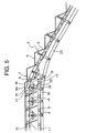
- Fig. 5 is a side view showing the vicinity of the forward path side upper curved section B of Fig. 4 in an enlarged state.
- a step 2 has a tread 4 for carrying a passenger; a riser 5 formed to be bent at a front or rear end of the tread 4; a driving roller shaft 6; a pair of rotatable driving rollers 7 attached to the driving roller shaft 6; a trailing roller shaft 8; and a pair of rotatable trailing rollers 9 attached to the trailing roller shaft 8.
- Each driving roller 7 is guided by a driving rail 10 supported by a main frame 1.
- Each trailing roller 9 is guided by a trailing rail 11 supported by the main frame 1. Note that shapes of the forward path side driving rail 10 and the forward path side trailing rail 11 are formed such that the tread 4 of the step 2 always keeps a level in forward path side sections.
- the driving roller shafts 6 of the adjacent steps 2 are coupled with each other by a link mechanism 13.
- the link mechanism 13 has first to fifth links 14 to 18.
- One end portion of the first link 14 is pivotably coupled to the driving roller shaft 6.
- the other end portion of the first link 14 is pivotably coupled to a middle portion of the third link 16 via a shaft 20.
- One end portion of the second link 15 is pivotably coupled to the driving roller shaft 6 of the step 2 adjacent to it.
- the other end portion of the second link 15 is pivotably coupled to a middle portion of the third link 16 via the shaft 20.
- One end portion of the fourth link 17 is pivotably coupled to a middle portion of the first link 14.
- One end portion of the fifth link 18 is pivotably coupled to a middle portion of the second link 15.
- the other end portions of the fourth and fifth links 17 and 18 are coupled to one end portion of the third link 16 via a sliding shaft 21.
- a guiding groove 16a for guiding slide of the sliding shaft 21 in a longitudinal direction of the third link 16 is provided at one end portion of the third link 16.
- a rotatable auxiliary roller 19 is provided at the other end portion of the third link 16. The auxiliary roller 19 is guided by an auxiliary rail 22 supported by the main frame 1.
- the auxiliary roller 19 is guided by the auxiliary rail 22, whereby the link mechanism 13 is transformed and a gap between the adjacent steps 2, that is, an interval between the driving roller shafts 6 of the adjacent steps 2 is changed.
- a track of the auxiliary rail 22 is designed so that the gap between the adjacent steps 2 changes.
- a speed of the step 2 is changed by changing the interval between the driving roller shafts 6 of the adjacent steps 2. That is, in a forward path upper side horizontal section A and a forward path lower side horizontal section E where a passenger gets on and off the elevator, the interval between the driving roller shafts 6 becomes the smallest, and the step 2 moves at low speed. In addition, in a forward path side constant inclined section C, the interval between the driving roller shafts 6 becomes the largest, and the step 2 moves at high speed. Moreover, in a forward path side upper curved section B and a forward path side lower curved section D, the interval between the driving roller shafts 6 is changed, and the step 2 accelerates or decelerates to travel.
- the first, second, fourth, and fifth links 14, 15, 17, and 18 constitute a so-called pantograph type quadric link mechanism, and an angle defined by the first and second links 14 and 15 can be increased and reduced with the third link 16 as a symmetrical axis. Accordingly, an interval between the driving roller shafts 6 coupled to the first and second links 14 and 15 can be changed.
- the interval between the driving roller shafts 6 of the adjacent steps 2 is the smallest.
- the link mechanism 13 moves in the same manner as a movement of a frame of an umbrella at the time when it is opened, and the interval between the driving roller shafts 6 of the adjacent steps 2 increases.
- the interval between the driving rail 10 and the auxiliary rail 22 is the smallest, and the interval between the driving roller shafts 6 of the adjacent steps 2 is the largest. Therefore, a speed of the step 2 in this area reaches the maximum.
- the first and second links 14 and 15 are arranged substantially in a straight line.
- the auxiliary rail 22 in each of the forward path side upper curved section B and the forward path side lower curved section D is formed substantially in a mere arc shape which smoothly joins the horizontal sections A and E and the constant inclined section C. Therefore, in the forward path side upper curved section B and the forward path side lower curved section D, a track of relative movement of a step 2 adjacent to a certain step 2 (track of a relative change of positions of the driving roller shafts 6 of the adjacent steps 2) is not in conformity with a shape of the riser 5.
- a length of the tread 4 is determined such that a gap is not generated between the riser 5 and a leading edge of the tread 4 of the step 2 adjacent to it in the horizontal sections A and E and the constant inclined section C.
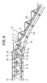
- the length of the tread 4 is determined as described above and the auxiliary rail 22 in each of the forward path side upper curved section B and the forward path side lower curved section D is formed substantially in a mere arc shape, interference occurs between the riser 5 and the leading edge of the tread 4, and smooth movement of the step 2 becomes difficult to be realized in the forward path side upper curved section B and the forward path side lower curved section D.
- a gap 23 is generated between the riser 5 and the leading edge of the tread 4 in the horizontal sections A and E and the constant inclined section C.
- the present invention has been made in order to solve the problem described above, and it is therefore an object of the present invention to obtain an escalator with a high speed inclined section which can prevent a leading edge of a tread from interfering with a riser of a step adjacent to it or a gap from being generated between a riser of a step and the tread which are adjacent to each other.
- an escalator with a high speed inclined section comprising: a main frame; a plurality of steps each having a tread for carrying a passenger; a riser provided at a front or rear end of the tread; a driving roller shaft; and a driving roller rotatable about the driving roller shaft, the plurality of steps being coupled in an endless manner to be moved so as to circulate along a circulation path; a plurality of link mechanisms which couple the driving roller shafts of the steps adjacent to each other for changing an interval between the driving roller shafts by being transformed; a rotatable auxiliary roller provided to each of the link mechanisms; a driving rail provided to the main frame for guiding a movement of the driving roller; and an auxiliary rail provided to the main frame for guiding a movement of the auxiliary roller and transforms the link mechanisms, wherein a shape of the auxiliary rail is set in a section between a forward path side horizontal section and a forward path side constant inclined section of the circulation path such that,
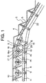
- Fig. 1 is a side view showing the vicinity of a forward path side upper curved section of an escalator with a high speed inclined section according to an embodiment of the present invention in an enlarged state
- Fig. 2 is a front view showing the link mechanism of the escalator with the high speed inclined section of Fig. 1.
- a step 2 has a tread 4 for carrying a passenger; a riser 5 formed to be bent at the front or rear end of the tread 4; a driving roller shaft 6; a pair of rotatable driving rollers 7 attached to the driving roller shaft 6, a trailing roller shaft 8; and a pair of rotatable trailing rollers 9 attached to the trailing roller shaft 8.
- the driving roller 7 is guided by a driving rail 10 supported by a main frame 1 (see Fig. 4).
- the trailing roller 9 is guided by a trailing rail 11 supported by the main frame 1. Note that shapes of the forward path side driving rail 10 and the forward path side trailing rail 11 are formed such that the tread 4 of the step 2 always keeps a level in forward path side sections.
- the driving roller shafts 6 of the adjacent steps 2 are coupled with each other by a link mechanism 13.
- the link mechanism 13 has first to fifth links 14 to 18.
- One end portion of the first link 14 is pivotably coupled to the driving roller shaft 6.
- the other end portion of the first link 14 is pivotably coupled to a middle portion of the third link 16 via a shaft 20.
- One end portion of the second link 15 is pivotably coupled to the driving roller shaft 6 of the step 2 adjacent to it.
- the other end portion of the second link 15 is pivotably coupled to a middle portion of the third link 16 via the shaft 20.
- One end portion of the fourth link 17 is pivotably coupled to a middle portion of the first link 14.
- One end portion of the fifth link 18 is pivotably coupled to a middle portion of the second link 15.
- the other end portions of the fourth and fifth links 17 and 18 are coupled to one end portion of the third link 16 via a sliding shaft 21.
- a guiding groove 16a for guiding slide of the sliding shaft 21 in a longitudinal direction of the third link 16 is provided at one end portion of the third link 16.
- a rotatable auxiliary roller 19 is provided at the other end portion of the third link 16. The auxiliary roller 19 is guided by an auxiliary rail 22 supported by the main frame 1.
- the auxiliary roller 19 is guided by the auxiliary rail 22, whereby the link mechanism 13 is transformed and a gap between the adjacent steps 2, that is, an interval between the driving roller shafts 6 of the adjacent steps 2 is changed.
- a track of the auxiliary rail 22 is designed such that a gap between the adjacent steps 2 changes.
- Fig. 3 is an explanatory view for explaining a determination method of a shape of the auxiliary rail 22 of Fig. 1.
- Fig. 3 is a view of the step 2 and the link mechanism 13 in the vicinity of a forward path side upper curved section B viewed from sides thereof, and shows the case in which a shape of the riser 5 is planar (linear) as an example.
- a shape of the riser 5 is planar (linear) as an example.
- only the first and second links 14 and 15 are shown in the link mechanism 13.
- a position of an axis H of the driving roller 7 in the step 2 on an upper step side is represented by coordinates (x 3 (i), y 3 (i))
- a position of an axis F of the driving roller 7 in the step 2 on a lower step side is represented by coordinates (x 1 (i), y 1 (i)).
- a distance between the driving roller shafts 6 in the horizontal section A is assumed to be w
- a position (x 3 (i), y 3 (i)) of the axis H is a point of intersection of a straight line with an inclination -tan 8 passing the point G and a circle of a radius R with a point L as a center
- the position (x 2 (i), y 2 (i)) of the point G and the position (x 3 (i), y 3 (i)) of the axis H are represented by the following expressions, respectively, in the same manner as in the expressions (11), (12), (13), and (14).
- x 3 (i) [a-p 1 (i)q 1 (i)- (a-p 1 (i)q 1 (i)) 2 -(1+p 1 (i) 2 )(a 2 +q 1 (i) 2 -R 2 ) ]/(1+p 1 (i) 2 )
- y 3 (i) p 1 (i)x 3 (i)+q 1 (i)
- the positions of the driving roller axes F and H at the time when the interval between the driving roller shafts 6 of the adjacent steps 2 changes in the upper curved section B (at the time when the speed of the step 2 changes) can be found. Then, if these positions are found, an axial position of the auxiliary roller 19 can also be found. This will be described using Fig. 2.
- Fig. 2 is an enlarged view of the link mechanism 13.
- a position of an axis (inflection point) P of the shaft 20 coupling the first link 14 and the second link 15 can be found as an point of intersection of a circle of a radius L 1 with the axis F as a center and a circle of a radius L 1 with the axis H as a center.
- a position of an axis Q of the auxiliary roller 19 can be found as a position to which a bisector of an angle defined by the first link 14 and the second link 15 is extended downward from the inflection point P by L 2 . If a moving track of the axis Q of the auxiliary roller 19 is found, a shape of the auxiliary rail 22 can be determined by drawing parallel lines which are apart from the track by a distance equivalent to a radius of the auxiliary roller 19.
- the auxiliary rail 22 of Fig. 1 is arranged in accordance with the shape determined by the above-mentioned method. As is evident from Fig. 1, the auxiliary rail 22 is not smoothly curved from the upper curved section B to the constant inclined section C and its curved shape changes discontinuously.
- the shape of the auxiliary . rail 22 is set such that the moving track of the relative positions of the adjacent steps 2 substantially coincides with the surface shape of the riser 5, an escalator with a high speed inclined section can be obtained in which, even at the time when the relative positions of the adjacent steps 2 change, the leading edge of the tread 4 of the step 2 adjacent to the riser 5 never interferes with the riser 5 or the gap 23 is never generated between the leading edge of the tread 4 and the riser 5.
- the shape of the auxiliary rail 22 can be determined in the same manner for the lower curved section.
- the shape of the auxiliary rail 22 can be determined in the same manner even if the shape of the riser 5 is a curved surface shape.
- the shape of the auxiliary rail 22 is determined directly from the moving track of the axis Q of the auxiliary roller 19, which is found from the shape of the riser 5, in the above-mentioned embodiment, the shape of the auxiliary rail 22 may be determined after approximating the moving track of the axis Q with an arc by a straight line, other polynomials, or the like.
- the shape of the auxiliary rail 22 may be determined after interpolating the moving loci by a curved line of a small R.
Landscapes
- Escalators And Moving Walkways (AREA)
- Inorganic Insulating Materials (AREA)
- Ticket-Dispensing Machines (AREA)
- Train Traffic Observation, Control, And Security (AREA)
Applications Claiming Priority (3)
| Application Number | Priority Date | Filing Date | Title |
|---|---|---|---|
| JP2001339432A JP2003146569A (ja) | 2001-11-05 | 2001-11-05 | 傾斜部高速エスカレータ |
| JP2001339432 | 2001-11-05 | ||
| PCT/JP2002/010613 WO2003040014A1 (fr) | 2001-11-05 | 2002-10-11 | Escalier mecanique grande vitesse pour pente |
Publications (3)
| Publication Number | Publication Date |
|---|---|
| EP1452476A1 true EP1452476A1 (de) | 2004-09-01 |
| EP1452476A4 EP1452476A4 (de) | 2005-06-15 |
| EP1452476B1 EP1452476B1 (de) | 2008-09-10 |
Family
ID=19153778
Family Applications (1)
| Application Number | Title | Priority Date | Filing Date |
|---|---|---|---|
| EP02772992A Expired - Lifetime EP1452476B1 (de) | 2001-11-05 | 2002-10-11 | Hochgeschwindigkeitsaufzug für abhang |
Country Status (9)
| Country | Link |
|---|---|
| US (1) | US6796416B2 (de) |
| EP (1) | EP1452476B1 (de) |
| JP (1) | JP2003146569A (de) |
| KR (1) | KR100521543B1 (de) |
| CN (1) | CN100418871C (de) |
| AT (1) | ATE407906T1 (de) |
| DE (1) | DE60228879D1 (de) |
| TW (1) | TWI288111B (de) |
| WO (1) | WO2003040014A1 (de) |
Families Citing this family (10)
| Publication number | Priority date | Publication date | Assignee | Title |
|---|---|---|---|---|
| JP4187971B2 (ja) * | 2002-01-21 | 2008-11-26 | 三菱電機株式会社 | 傾斜部高速エスカレーター |
| JP4031249B2 (ja) * | 2002-01-23 | 2008-01-09 | 三菱電機株式会社 | 傾斜部高速エスカレーター |
| JP4236846B2 (ja) * | 2002-01-23 | 2009-03-11 | 三菱電機株式会社 | 傾斜部高速エスカレーター |
| US7124875B2 (en) * | 2002-01-23 | 2006-10-24 | Mitsubishi Denki Kabushiki Kaisha | Escalator with high speed inclined section |
| JP4707384B2 (ja) * | 2004-12-17 | 2011-06-22 | 東芝エレベータ株式会社 | 中間加速型エスカレータ |
| ES2294972B1 (es) * | 2007-09-05 | 2009-04-01 | Thyssenkrupp Elevator Innovation Center, S.A. | Sistema de curva de volteo para sistema de transporte por cadena. |
| ES2453206B1 (es) | 2013-09-25 | 2015-01-12 | Thyssenkrupp Elevator Innovation Center, S.A. | Sistema de tracción para un sistema de transporte |
| EP3511284B1 (de) | 2018-01-10 | 2021-09-15 | Otis Elevator Company | Beweglicher fahrsteig |
| CN113631796B (zh) * | 2019-03-22 | 2025-04-25 | 株式会社久保田 | 管输送装置及管道铺设坑道内的管的接合方法 |
| JP7100298B2 (ja) * | 2020-10-26 | 2022-07-13 | フジテック株式会社 | マンコンベヤ |
Family Cites Families (16)
| Publication number | Priority date | Publication date | Assignee | Title |
|---|---|---|---|---|
| BE756837R (fr) * | 1969-09-30 | 1971-03-01 | Pirelli | Trottoir roulant |
| ES415246A1 (es) * | 1972-06-30 | 1976-07-16 | Patin | Dispositivo para el arrastre a velocidad variable de ele- mentos moviles. |
| SE407372B (sv) * | 1973-06-22 | 1979-03-26 | Saiag Spa | Bandtransportor innefattande ett transportband, sammansatt av ett flertal, pa varandra foljande bandsegment |
| FR2236391A5 (de) * | 1973-07-02 | 1975-01-31 | Stephanois Rech Meca Hydr Cent | |
| JPS51116586A (en) * | 1975-04-07 | 1976-10-14 | Hitachi Ltd | Escalator |
| US4197933A (en) * | 1977-12-05 | 1980-04-15 | The Boeing Company | Linear induction drive system for accelerating and decelerating moving walkway |
| US4240537A (en) * | 1978-04-18 | 1980-12-23 | The Boeing Company | Accelerating and decelerating handrail |
| US4462514A (en) * | 1981-11-16 | 1984-07-31 | The Boeing Company | Accelerating and decelerating walkway handrail |
| US4930622A (en) * | 1989-03-27 | 1990-06-05 | Otis Elevator Company | Curved escalator with fixed center constant radius path of travel |
| US4953685A (en) * | 1989-08-10 | 1990-09-04 | Otis Elevator Company | Step chain for curved escalator |
| JP2540965B2 (ja) * | 1990-01-16 | 1996-10-09 | 三菱電機株式会社 | 中間高速エスカレ―タ― |
| ES2179720B1 (es) * | 1999-11-19 | 2004-03-16 | Thyssen Norte S A | Pasillo de aceleracion. |
| JP4080753B2 (ja) | 2001-04-19 | 2008-04-23 | 三菱電機株式会社 | 傾斜部高速エスカレーター |
| JP3318751B1 (ja) | 2001-05-09 | 2002-08-26 | 有限会社宮下プラントエンジニアリング | スライド式高速エスカレータ装置 |
| US6685003B2 (en) * | 2001-12-28 | 2004-02-03 | Otis Elevator Company | Pulse-free escalator |
| JP4031249B2 (ja) * | 2002-01-23 | 2008-01-09 | 三菱電機株式会社 | 傾斜部高速エスカレーター |
-
2001
- 2001-11-05 JP JP2001339432A patent/JP2003146569A/ja active Pending
-
2002
- 2002-10-11 US US10/451,523 patent/US6796416B2/en not_active Expired - Lifetime
- 2002-10-11 CN CNB028082710A patent/CN100418871C/zh not_active Expired - Fee Related
- 2002-10-11 KR KR10-2003-7012437A patent/KR100521543B1/ko not_active Expired - Fee Related
- 2002-10-11 DE DE60228879T patent/DE60228879D1/de not_active Expired - Lifetime
- 2002-10-11 WO PCT/JP2002/010613 patent/WO2003040014A1/ja not_active Ceased
- 2002-10-11 AT AT02772992T patent/ATE407906T1/de not_active IP Right Cessation
- 2002-10-11 EP EP02772992A patent/EP1452476B1/de not_active Expired - Lifetime
-
2003
- 2003-03-24 TW TW092106467A patent/TWI288111B/zh not_active IP Right Cessation
Non-Patent Citations (2)
| Title |
|---|
| No further relevant documents disclosed * |
| See also references of WO03040014A1 * |
Also Published As
| Publication number | Publication date |
|---|---|
| EP1452476A4 (de) | 2005-06-15 |
| US6796416B2 (en) | 2004-09-28 |
| WO2003040014A1 (fr) | 2003-05-15 |
| CN1503761A (zh) | 2004-06-09 |
| EP1452476B1 (de) | 2008-09-10 |
| DE60228879D1 (de) | 2008-10-23 |
| TW200418710A (en) | 2004-10-01 |
| US20040060799A1 (en) | 2004-04-01 |
| KR100521543B1 (ko) | 2005-10-12 |
| TWI288111B (en) | 2007-10-11 |
| KR20040016847A (ko) | 2004-02-25 |
| CN100418871C (zh) | 2008-09-17 |
| JP2003146569A (ja) | 2003-05-21 |
| ATE407906T1 (de) | 2008-09-15 |
Similar Documents
| Publication | Publication Date | Title |
|---|---|---|
| EP1452476B1 (de) | Hochgeschwindigkeitsaufzug für abhang | |
| EP1431234B1 (de) | Hochgeschwindigkeitsfahrtreppe mit geneigtem teil | |
| JP4236846B2 (ja) | 傾斜部高速エスカレーター | |
| JP4187971B2 (ja) | 傾斜部高速エスカレーター | |
| EP1331195A2 (de) | Fahrtreppe mit schiefen Hochgeschwindigkeitsteilbereichen | |
| JP2004224567A (ja) | コンベア装置 | |
| JP4029919B2 (ja) | 傾斜部高速エスカレータ | |
| EP1468953B1 (de) | Hochgeschwindigkeitsfahrtreppe mit geneigtem teil | |
| EP1468951A1 (de) | Hochgeschwindigkeitsfahrtreppe mit geneigtem teil | |
| WO2003062120A1 (fr) | Escalator tres rapide presentant une partie en pente | |
| JP4388848B2 (ja) | 移動手摺り | |
| JP2006008308A (ja) | 傾斜部高速エスカレータ | |
| JP2005067878A (ja) | 傾斜部高速エスカレータ | |
| WO2003062123A1 (fr) | Escalier roulant comportant une partie inclinee tres rapide |
Legal Events
| Date | Code | Title | Description |
|---|---|---|---|
| PUAI | Public reference made under article 153(3) epc to a published international application that has entered the european phase |
Free format text: ORIGINAL CODE: 0009012 |
|
| 17P | Request for examination filed |
Effective date: 20030801 |
|
| AK | Designated contracting states |
Kind code of ref document: A1 Designated state(s): AT BE BG CH CY CZ DE DK EE ES FI FR GB GR IE IT LI LU MC NL PT SE TR |
|
| AX | Request for extension of the european patent |
Extension state: AL LT LV MK RO SI |
|
| A4 | Supplementary search report drawn up and despatched |
Effective date: 20050502 |
|
| RAP1 | Party data changed (applicant data changed or rights of an application transferred) |
Owner name: MITSUBISHI DENKI KABUSHIKI KAISHA |
|
| GRAP | Despatch of communication of intention to grant a patent |
Free format text: ORIGINAL CODE: EPIDOSNIGR1 |
|
| GRAS | Grant fee paid |
Free format text: ORIGINAL CODE: EPIDOSNIGR3 |
|
| GRAA | (expected) grant |
Free format text: ORIGINAL CODE: 0009210 |
|
| RIN1 | Information on inventor provided before grant (corrected) |
Inventor name: YUMURA, TAKASHI,MITSUBISHI DENKI K.K. Inventor name: NAKAMURA, JOICHI.,T Inventor name: OGURA, MANABU,MITSUBISHI DENKI K.K. |
|
| AK | Designated contracting states |
Kind code of ref document: B1 Designated state(s): AT DE FR NL |
|
| REF | Corresponds to: |
Ref document number: 60228879 Country of ref document: DE Date of ref document: 20081023 Kind code of ref document: P |
|
| PG25 | Lapsed in a contracting state [announced via postgrant information from national office to epo] |
Ref country code: AT Free format text: LAPSE BECAUSE OF FAILURE TO SUBMIT A TRANSLATION OF THE DESCRIPTION OR TO PAY THE FEE WITHIN THE PRESCRIBED TIME-LIMIT Effective date: 20080910 |
|
| NLV1 | Nl: lapsed or annulled due to failure to fulfill the requirements of art. 29p and 29m of the patents act | ||
| PG25 | Lapsed in a contracting state [announced via postgrant information from national office to epo] |
Ref country code: NL Free format text: LAPSE BECAUSE OF FAILURE TO SUBMIT A TRANSLATION OF THE DESCRIPTION OR TO PAY THE FEE WITHIN THE PRESCRIBED TIME-LIMIT Effective date: 20080910 |
|
| PLBE | No opposition filed within time limit |
Free format text: ORIGINAL CODE: 0009261 |
|
| STAA | Information on the status of an ep patent application or granted ep patent |
Free format text: STATUS: NO OPPOSITION FILED WITHIN TIME LIMIT |
|
| 26N | No opposition filed |
Effective date: 20090611 |
|
| REG | Reference to a national code |
Ref country code: FR Ref legal event code: ST Effective date: 20090831 |
|
| REG | Reference to a national code |
Ref country code: DE Ref legal event code: R084 Ref document number: 60228879 Country of ref document: DE Effective date: 20110628 Ref country code: DE Ref legal event code: R084 Ref document number: 60228879 Country of ref document: DE Effective date: 20110506 |
|
| PG25 | Lapsed in a contracting state [announced via postgrant information from national office to epo] |
Ref country code: FR Free format text: LAPSE BECAUSE OF NON-PAYMENT OF DUE FEES Effective date: 20081031 |
|
| PGFP | Annual fee paid to national office [announced via postgrant information from national office to epo] |
Ref country code: DE Payment date: 20180925 Year of fee payment: 17 |
|
| REG | Reference to a national code |
Ref country code: DE Ref legal event code: R119 Ref document number: 60228879 Country of ref document: DE |
|
| PG25 | Lapsed in a contracting state [announced via postgrant information from national office to epo] |
Ref country code: DE Free format text: LAPSE BECAUSE OF NON-PAYMENT OF DUE FEES Effective date: 20200501 |