EP1468951A1 - Hochgeschwindigkeitsfahrtreppe mit geneigtem teil - Google Patents
Hochgeschwindigkeitsfahrtreppe mit geneigtem teil Download PDFInfo
- Publication number
- EP1468951A1 EP1468951A1 EP02783749A EP02783749A EP1468951A1 EP 1468951 A1 EP1468951 A1 EP 1468951A1 EP 02783749 A EP02783749 A EP 02783749A EP 02783749 A EP02783749 A EP 02783749A EP 1468951 A1 EP1468951 A1 EP 1468951A1
- Authority
- EP
- European Patent Office
- Prior art keywords
- handrail
- speed
- steps
- landing
- moving
- Prior art date
- Legal status (The legal status is an assumption and is not a legal conclusion. Google has not performed a legal analysis and makes no representation as to the accuracy of the status listed.)
- Withdrawn
Links
Images




Classifications
-
- B—PERFORMING OPERATIONS; TRANSPORTING
- B66—HOISTING; LIFTING; HAULING
- B66B—ELEVATORS; ESCALATORS OR MOVING WALKWAYS
- B66B23/00—Component parts of escalators or moving walkways
- B66B23/22—Balustrades
- B66B23/24—Handrails
- B66B23/26—Handrails of variable speed type
-
- B—PERFORMING OPERATIONS; TRANSPORTING
- B66—HOISTING; LIFTING; HAULING
- B66B—ELEVATORS; ESCALATORS OR MOVING WALKWAYS
- B66B21/00—Kinds or types of escalators or moving walkways
- B66B21/02—Escalators
Definitions
- the present invention relates to a high-speed inclined portion escalator in which a traveling speed of steps in an intermediate inclined portion is faster than a traveling speed of the steps in an upper landing portion and a lower landing portion.
- high-speed inclined portion escalators have been proposed in which it is possible for the amount of time spent riding the escalator to be shortened by operating at low speed in upper and lower landing portions where the passengers get on and off, operating to accelerate and decelerate in an upper curved portion and a lower curved portion, and operating at high speed in an intermediate inclined portion.
- Ahigh-speed inclined portion escalator of this kind is disclosed in Japanese Patent Laid-Open No. SHO 51-116586 (Gazette), for example.
- Figure 8 is a schematic side elevation showing an example of a conventional high-speed inclined portion escalator.
- a plurality of steps 2 linked endlessly are disposed on a main frame 1.
- the steps 2 are driven by a drive unit (a step driving means) 3, and are moved cyclically.
- a pair of railings 4 are disposed upright on an upper portion of the main frame 1.
- the railings 4 are disposed on both sides in a width direction of the steps 2.
- Main tracks 5 forming a cyclic path for the steps 2, trailing tracks 6 for controlling an attitude of the steps 2, and auxiliary tracks 7 for changing a pitch between adjacent steps 2 are disposed on the main frame 1.
- Moving handrail apparatuses 25 are disposed on the railings 4.
- the moving handrail apparatuses 25 have endless moving handrails 26 that are moved cyclically.
- the cyclic path for the steps 2 has: a forward section, a return section, an upper inversion portion, and a lower inversion portion.
- the forward section of the cyclic path has: an upper landing portion (an upper horizontal portion) A, an upper curved portion B, an intermediate inclined portion (a constant inclination portion) C, a lower curved portion D, and a lower landing portion (a lower horizontal portion) E.
- Figure 9 is a side elevation showing a vicinity of the upper landing portion in Figure 8 enlarged.
- the steps 2 have: a tread 8 for carrying passengers; a riser 9 disposed upright on one edge in a depth direction of the tread 8; a step link roller shaft 10; a pair of step link rollers 11 that are rotatable around the step link roller shaft 10; a trailing roller shaft 12; and a pair of trailing rollers 13 that are rotatable around the trailing roller shaft 12.
- the step link rollers 11 roll along the main tracks 5.
- the trailing rollers 13 roll along the trailing tracks 6.
- the step link roller shafts 10 of mutually-adjacent steps 2 are linked to each other by a pair of linking mechanisms (folding links) 14.
- Each of the linking mechanisms 14 has first to fifth links 15 to 19.
- a first end portion of the first link 15 is linked pivotably to the step link roller shaft 10.
- a second end portion of the first link 15 is linked pivotably to an intermediate portion of the third link 17 by means of a shaft 20.
- a first end portion of the second link 16 is linked pivotably to the step link roller shaft 10 of the adjacent step 2.
- a second end portion of the second link 16 is linked pivotably by means of the shaft 20 to the intermediate portion of the third link 17.
- a first end portion of the fourth link 18 is connected pivotably to an intermediate portion of the first link 15.
- a first end portion of the fifth link 19 is connected pivotably to an intermediate portion of the second link 16.
- Second end portions of the fourth and fifth links 18 and 19 are linked to a first end portion of the third link 17 by means of a sliding shaft 21.
- a guiding groove 17a for guiding sliding of the sliding shaft 21 in the longitudinal direction of the third link 17 is disposed on the first end portion of the third link 17.
- a rotatable auxiliary roller 22 is disposed on a second end portion of the third link 17. The auxiliary roller 22 is guided by the auxiliary tracks 7.
- a pitch between the step link roller shafts 10, and thus a relative pitch between adjacent steps 2 is changed by the auxiliary rollers 22 being guided by the auxiliary tracks 7 to change the shape of the linking mechanisms 14 so as to fold and unfold.
- tracks of the auxiliary tracks 7 are designed such that the relative pitch between adjacent steps 2 changes.
- the speed of the steps 2 is changed by changing the pitch between the step link roller shafts 10 of adjacent steps 2.
- the pitch between the step link roller shafts 10 is minimized and the steps 2 move at low speed.
- the pitch between the step link roller shafts 10 is maximized and the steps 2 move at high speed.
- the pitch between the step link roller shafts 10 changes and the steps 2 accelerate or decelerate.
- the first, second, fourth, and fifth links 15, 16, 18, and 19 constitute a four-link "pantograph" linking mechanism, enabling an angle formed by the first and second links 15 and 16 to be enlarged and reduced with the third link 17 as an axis of symmetry.
- the pitch between the step link roller shafts 10 linked by the first and second links 15 and 16 can be changed.
- the pitch between the step link roller shafts 10 of adjacent steps 2 is minimized. From this state, when the distance between the main tracks 5 and the auxiliary tracks 7 is reduced, the linking mechanisms 14 operate in a similar manner to the operation of the frame of an umbrella as the umbrella is being opened out, increasing the pitch between the step link roller shafts 10 of the adjacent steps 2.
- a traveling speed of the moving handrails 26 is constant over an entire region, such as being set so as to be equal to a traveling speed of the steps 2 in the intermediate inclined portion C, for example. Because of this, differences in amount of movement arise between the moving handrails 26 and the steps 2 when moving from the intermediate inclined portion C to the landing portions A and E, or vice versa, making the moving handrails 26 difficult to hold onto.
- the present invention aims to solve the above problems and an object of the present invention is to provide a high-speed inclined portion escalator capable of suppressing a difference between a traveling speed of a moving handrail and a traveling speed of a step in order to make the moving handrail easy to hold onto even when the step changes speed.
- a high-speed inclined portion escalator including: a main frame; a cyclic path disposed on the main frame, the cyclic path having an upper landing portion, a lower landing portion, and an intermediate inclined portion positioned between the upper landing portion and the lower landing portion, an upper curved portion positioned between the upper landing portion and the intermediate inclined portion, and a lower curved portion positioned between the lower landing portion and the intermediate inclined portion; a plurality of steps linked endlessly and moved cyclically along the cyclic path; an upper portion handrail apparatus disposed on the main frame in a vicinity of the upper landing portion, the upper portion handrail apparatus having an endless upper portionmovinghandrailthatismovedcyclically; a lower portion handrail apparatus disposed on the main frame in a vicinity of the lower landing portion, the lower portion handrail apparatus having an endless lower portion moving handrail that is moved cyclically; and an intermediate handrail apparatus disposed on the main frame between the upper portion handrail apparatus and the
- Figure 1 is a schematic side elevation showing a high-speed inclined portion escalator according to Embodiment 1 of the present invention.
- a plurality of steps 2 linked endlessly are disposed on a main frame 1.
- the steps 2 are driven by a drive unit (a step driving means) 3, and are moved cyclically.
- Main tracks 5 forming a cyclic path for the steps 2, trailing tracks 6 for controlling an attitude of the steps 2, and auxiliary tracks 7 for changing a pitch between adjacent steps 2 are disposed on the main frame 1.
- the cyclic path for the steps 2 has: a forward section, a return section, an upper inversion portion, and a lower inversion portion.
- the forward section of the cyclic path has: an upper landing portion (an upper horizontal portion) A, an upper curved portion B, an intermediate inclined portion (a constant inclination portion) C, a lower curved portion D, and a lower landing portion (a lower horizontal portion) E.
- the intermediate inclined portion C is positioned between the upper landing portion A and the lower landing portion E.
- the upper curved portion B is positioned between the upper landing portion A and the intermediate inclined portion C.
- the lower curved portion D is positioned between the lower landing portion E and the intermediate inclined portion C.
- a pair of railings 31 are disposed upright on an upper portion of the main frame 1.
- the railings 31 are disposed on both sides in a width direction of the steps 2.
- Each of the railings 31 includes: an upper portion railing 32 disposed in a vicinity of the upper landing portion A; a lower portion railing 33 disposed in a vicinity of the lower landing portion E; and an intermediate railing 34 disposed between the upper portion railing 32 and the lower portion railing 33.
- Upper portion handrail apparatuses 35 are disposed on the upper portion railings 32. Each of the upper portion handrail apparatuses 35 has an endless upper portion moving handrail 36 that is moved cyclically.
- Lower portion handrail apparatuses 37 are disposed on the lower portion railings 33. Each of the lower portion handrail apparatuses 37 has an endless lower portion moving handrail 38 that is moved cyclically.
- Intermediate handrail apparatuses 39 are disposed on the intermediate railings 34. Each of the intermediate handrail apparatuses 39 has an endless intermediate moving handrail 40 that is moved cyclically.
- the upper portion handrail apparatuses 35, the intermediate handrail apparatuses 39, and the lower portion handrail apparatuses 37 are disposed in series in a longitudinal direction of the main frame 1 (left-to-right in Figure 1). In other words, the handrail apparatuses are divided into three portions in the longitudinal direction of the main frame 1.
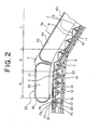
- Figure 2 is a side elevation showing a vicinity of the upper curved portion B in Figure 1 enlarged.
- the steps 2 have: a tread 8 for carrying passengers; a riser 9 disposed upright on one edge in a depth direction of the tread 8; a step link roller shaft 10; step link rollers 11 that are rotatable around the step link roller shaft 10; a trailing roller shaft 12; and trailing rollers 13 that are rotatable around the trailing roller shaft 12.
- the step link rollers 11 roll along the main tracks 5.
- the trailing rollers 13 roll along the trailing tracks 6.
- the step link roller shafts 10 of mutually-adjacent steps 2 are linked to each other by linking mechanisms (folding links) 14.
- the linking mechanisms 14 have first to fifth links 15 to 19.
- a first end portion of the first link 15 is linked pivotably to the step link roller shaft 10.
- a second end portion of the first link 15 is linked pivotably to an intermediate portion of the third link 17 by means of a shaft 20.
- a first end portion of the second link 16 is linked pivotably to the step link roller shaft 10 of the adjacent step 2.
- a second end portion of the second link 16 is linked pivotably by means of the shaft 20 to the intermediate portion of the third link 17.
- a first end portion of the fourth link 18 is connected pivotably to an intermediate portion of the first link 15.
- a first end portion of the fifth link 19 is connected pivotably to an intermediate portion of the second link 16.
- Second end portions of the fourth and fifth links 18 and 19 are linked to a first end portion of the third link 17 by means of a sliding shaft 21.
- a guiding groove 17a for guiding sliding of the sliding shaft 21 in the longitudinal direction of the third link 17 is disposed on the first end portion of the third link 17.
- a rotatable auxiliary roller 22 is disposed on a second end portion of the third link 17. The auxiliary roller 22 is guided by the auxiliary tracks 7.
- a pitch between the step link roller shafts 10, and thus a relative pitch between adjacent steps 2 is changed by the auxiliary rollers 22 being guided by the auxiliary tracks 7 to change the shape of the linking mechanisms 14 so as to fold and unfold.
- tracks of the auxiliary tracks 7 are designed such that the relative pitch between adjacent steps 2 changes.
- a traveling speed of the steps 2 in the intermediate inclined portion C is set so as to be faster than a traveling speed of the steps 2 in the upper landing portion A and the lower landing portion E. Furthermore, the upper portion moving handrails 36 and the lower portion moving handrails 38 are moved cyclically at a speed corresponding to the traveling speed of the steps 2 in the upper landing portion A and the lower landing portion E, and the intermediate moving handrails 40 are moved cyclically at a faster speed than the upper portion moving handrails 36 and the lower portion moving handrails 38 so as to correspond to the traveling speed of the steps 2 in the intermediate inclined portion C.
- the upper portion moving handrails 36 and the lower portion moving handrails 38 are moved cyclically at a speed equal to that of the traveling speed of the steps 2 in the upper landing portion A and the lower landing portion E, and the intermediate moving handrails 40 is moved cyclically at a speed equal to that of the traveling speed of the steps 2 in the intermediate inclined portion C.
- the upper portion moving handrails 36 and the lower portion moving handrails 38 each have a horizontal portion 41 extending horizontally.
- the intermediate moving handrails 40 have intermediate straight portions 42 extending parallel to the intermediate inclined portion C. Boundaries between the upper portion handrail apparatuses 35 and the intermediate handrail apparatuses 39 and between the lower portion handrail apparatuses 37 and the intermediate handrail apparatuses 39 are positioned in a vicinity of points of intersection F between straight lines extending from the horizontal portions 41 and straight lines extending from the intermediate straight portions 42.
- the speed of the steps 2 is changed by changing the pitch between the step link roller shafts 10 of adjacent steps 2.
- the pitch between the step link roller shafts 10 is minimized and the steps 2 move at low speed.
- the pitch between the step link roller shafts 10 is maximized and the steps 2 move at high speed.
- the pitch between the step link roller shafts 10 changes and the steps 2 accelerate or decelerate.
- the first, second, fourth, and fifth links 15, 16, 18, and 19 constitute a four-link "pantograph" linking mechanism, enabling an angle formed by the first and second links 15 and 16 to be enlarged and reduced with the third link 17 as an axis of symmetry.
- the pitch between the step link roller shafts 10 linked by the first and second links 15 and 16 can be changed.
- the pitch between the step link roller shafts 10 of adjacent steps 2 is minimized. From this state, when the distance between the main tracks 5 and the auxiliary tracks 7 is reduced, the linking mechanisms 14 operate in a similar manner to the operation of the frame of an umbrella as the umbrella is being opened out, increasing the pitch between the step link roller shafts 10 of the adjacent steps 2.
- the distance between the main tracks 5 and the auxiliary tracks 7 is smallest in the intermediate inclined portion C in Figure 1, and the pitch between the step link roller shafts 10 of the adjacent steps 2 is maximized. Consequently, the speed of the steps 2 is maximized in this region.
- the first and second links 15 and 16 are disposed almost in a straight line.
- boundaries between the upper portion handrail apparatuses 35 and the intermediate handrail apparatuses 39 and between the lower portion handrail apparatuses 37 and the intermediate handrail apparatuses 39 are positioned in a vicinity of points of intersection F between straight lines extending from the horizontal portions 41 and straight lines extending from the intermediate straight portions 42. Because of this, as shown in Figure 2, for example, changeover between the handrails can be performed where a direction of travel of the upper portion moving handrails 36 or the intermediate moving handrails 40 changes. Consequently, the changeover between the handrails is easy to time, enabling the changeover operation to be performed smoothly.
- the upper curved portion B is shown in Figure 2, but a similar construction can also be adopted for the lower curved portion D.
- the traveling speed of the upper portion moving handrails 36 and the lower portion moving handrails 38 may also be set to an intermediate speed between the traveling speed of the steps 2 in the upper landing portion A and the lower landing portion E and the traveling speed of the steps 2 in the intermediate inclined portion C.
- differences between the traveling speed of the upper portion moving handrails 36 and the lower portion moving handrails 38 and the traveling speed of the intermediate moving handrails 40 can be reduced.
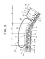
- Figure 3 is a side elevation showing part of a high-speed inclined portion escalator according to Embodiment 2 of the present invention.
- a boundary between an upper portion handrail apparatus 35 and an intermediate handrail apparatus 39 is positioned in a vicinity of a boundary between an upper curved portion B and an intermediate inclined portion C.
- a boundary between a lower portion handrail apparatus 37 and the intermediate handrail apparatus 39 is positioned in a vicinity of a boundary between a lower curved portion D and the intermediate inclined portion C.
- the rest of the construction is similar to that of Embodiment 1.
- both the upper portion handrail apparatus 35 and the lower portion handrail apparatus 37 are extended to a vicinity of the intermediate inclined portion C, but either one may also be extended independently.
- Figure 4 is a side elevation showing part of a high-speed inclined portion escalator according to Embodiment 3 of the present invention.
- a boundary between an upper portion handrail apparatus 35 and an intermediate handrail apparatus 39 is positioned in a vicinity of a boundary between an upper curved portion B and an upper landing portion A.
- a boundary between a lower portion handrail apparatus 37 and the intermediate handrail apparatus 39 is positioned in a vicinity of a boundary between a lower curved portion D and a lower landing portion E.
- the rest of the construction is similar to that of Embodiment 1.
- both end portions of the intermediate handrail apparatus 39 are extended to a vicinity of the landing portions, but either one of the end portions may also be extended to a vicinity of a landing portion independently.
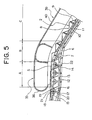
- Figure 5 is a side elevation showing part of a high-speed inclined portion escalator according to Embodiment 4 of the present invention
- Figure 6 is a plan showing part of Figure 5.
- upper portion handrail apparatuses 35 and intermediate handrail apparatuses 39 each extend to an upper curved portion B. Because of this, a disposition range of the intermediate handrail apparatuses 39 in a longitudinal direction of the main frame 1 overlaps partially with a disposition range of the upper portion handrail apparatuses 35 in the upper curved portion B. In a region where the disposition ranges overlap, the intermediate handrail apparatuses 39 are disposed outside the upper portion handrail apparatuses 35 in a width direction of the steps 2 (top-to-bottom in Figure 6). In other words, upper end portions of the intermediate handrail apparatuses 39 overlap with the upper portion handrail apparatuses 35 in the width direction of the steps 2.
- the time required for a changeover between handrails i.e., the time spent not holding a handrail
- the timing for changing over between the handrails can also be selected by a passenger within the region where the disposition ranges overlap.
- the changeover can be made before differences in the amount of movement between the moving handrails 36 and 40 and the steps 2 become large.
- the upper portion handrail apparatuses 35 and the intermediate handrail apparatuses 39 are disposed so as to overlap partially , but the lower portion handrail apparatuses 37 and the intermediate handrail apparatuses 39 may also be disposed so as to overlap partially.
- the intermediate handrail apparatuses 39 are disposed outside the upper portion handrail apparatuses 35, but the upper portion handrail apparatuses 35 and the lower portion handrail apparatuses 37 may also be disposed outside the intermediate handrail apparatuses 39 in the width direction of the steps 2.
- spacing between the intermediate moving handrails 40 is partially widened in the width direction of the steps 2, but the spacing may also be widened over the entirety of the intermediate moving handrails 40.
- the spacing between the upper portion moving handrails 36 and the spacing between the lower portion moving handrails 38 may also be made wider than the spacing between the intermediate moving handrails 40.
- boundaries between the upper portion handrail apparatuses 35 and the intermediate handrail apparatuses 39 and boundaries between lower portion handrail apparatuses 37 and the intermediate handrail apparatuses 39 can each be set separately, making it possible to combine the setting methods of Embodiments 1 to 4 freely.
- Figure 7 is a schematic side elevation showing a high-speed inclined portion escalator according to Embodiment 5 of the present invention.
- a first sprocket 52 is mounted to a drive shaft 51 of a drive unit 3 so as to be rotated integrally with the drive shaft 51.
- Second to fourth sprockets 53 to 55 are disposed in a vicinity of an upper curved portion of a main frame 1.
- the second to fourth sprockets 53 to 55 are disposed coaxially and are rotated together.
- a diameter of the third sprocket 54 is greater than a diameter of the second sprocket 53, and a diameter of the fourth sprocket 55 is greater than the diameter of the third sprocket 54.
- An endless first driving chain 56 is wound around the first sprocket 52 and the second sprocket 53. Rotation of the first sprocket 52 is transmitted to the second to fourth sprockets 53 to 55 by means of the first driving chain 56.
- Fifth and sixth sprockets 57 and 58 are disposed in a vicinity of a lower curved portion of the main frame 1.
- the fifth and sixth sprockets 57 and 58 are disposed coaxially and are rotated together.
- a diameter of the sixth sprocket 58 is greater than a diameter of the fifth sprocket 57.
- An endless second driving chain 59 is wound around the first sprocket 52 and the fifth sprocket 57. Rotation of the first sprocket 52 is transmitted to the fifth and sixth sprockets 57 and 58 by means of the second driving chain 59.
- An upper portion handrail apparatus 35 has a pair of upper portion step link rollers 60 and 61 disposed so as to be positioned on mutually opposite sides of a return portion of an upper portion moving handrail 36. Rotation of the third sprocket 54 is transmitted to the upper portion step link roller 60 by means of an endless upper portion transmission chain 62. The upper portion moving handrail 36 is moved cyclically by rotation of the upper portion step link roller 60.
- An intermediate handrail apparatus 39 has a pair of intermediate step link rollers 63 and 64 disposed so as to be positioned on mutually opposite sides of a return portion of an intermediate moving handrail 40. Rotation of the fourth sprocket 55 is transmitted to the intermediate step link roller 63 by means of an endless intermediate transmission chain 65. The intermediate moving handrail 40 is moved cyclically by rotation of the intermediate step link roller 63. A speed ratio between the upper portion moving handrail 36 and the intermediate moving handrails 40 is set by a ratio between the diameter of the third sprocket 54 and the diameter of the fourth sprocket 55.
- a lower portion handrail apparatus 37 has a pair of lower portion step link rollers 66 and 67 disposed so as to be positioned on mutually opposite sides of a return portion of a lower portion moving handrail 38. Rotation of the sixth sprocket 58 is transmitted to the lower portion step link roller 66 by means of an endless lower portion transmission chain 68. The lower portion moving handrail 38 is moved cyclically by rotation of the lower portion step link roller 66.
- the diameters of the first, second, and fifth sprockets 52, 53, and 57 are equal to each other, and the diameters of the third and sixth sprockets 54 and 58 are equal to each other.
- the lower portion moving handrail 38 is moved at a speed equal to that of the upper portion moving handrail 36.
- the upper portion moving handrail 36, the lower portion moving handrails 38, and the intermediate moving handrail 40 are moved cyclically by a drive unit 3 that drives steps 2 (see Figure 1). Consequently, a single drive unit 3 is sufficient, enabling costs to be reduced.
- the upper portion moving handrail 36 can be operated at a speed equal to that of the steps 2 in an upper landing portion, the intermediate moving handrail 40 at a speed equal to that of the steps 2 in an intermediate inclined portion, and the lower portion moving handrails 38 at a speed equal to that of the steps 2 in a lower landing portion.
- transmission of power is performed by a combination of chains and sprockets, but other power transmission mechanisms such as combinations of ropes or belts and pulleys, for example, may also be used.
- the moving handrails 36, 38, and 40 are driven using the drive unit 3 that drives the steps 2, but a drive source that is separate from the drive unit 3 may also be used for the moving handrails 36, 38, and 40.
- the moving handrails 36, 38, and 40 may also each be driven by a separate drive source, or they may also be driven by a common drive source.
- Embodiments 1 to 5 three handrail apparatuses 35, 37, and 39 are used, but four or more handrail apparatuses may also be used, or any one of the handrail apparatuses 35, 37, and 39 may also be divided into a plurality of parts.
Landscapes
- Escalators And Moving Walkways (AREA)
Applications Claiming Priority (3)
| Application Number | Priority Date | Filing Date | Title |
|---|---|---|---|
| JP2002013321 | 2002-01-22 | ||
| JP2002013321A JP2003212462A (ja) | 2002-01-22 | 2002-01-22 | 傾斜部高速エスカレーター |
| PCT/JP2002/012668 WO2003062118A1 (en) | 2002-01-22 | 2002-12-03 | Sloped part high-speed escalator |
Publications (2)
| Publication Number | Publication Date |
|---|---|
| EP1468951A1 true EP1468951A1 (de) | 2004-10-20 |
| EP1468951A4 EP1468951A4 (de) | 2006-11-29 |
Family
ID=27606063
Family Applications (1)
| Application Number | Title | Priority Date | Filing Date |
|---|---|---|---|
| EP02783749A Withdrawn EP1468951A4 (de) | 2002-01-22 | 2002-12-03 | Hochgeschwindigkeitsfahrtreppe mit geneigtem teil |
Country Status (4)
| Country | Link |
|---|---|
| EP (1) | EP1468951A4 (de) |
| JP (1) | JP2003212462A (de) |
| CN (1) | CN1541181A (de) |
| WO (1) | WO2003062118A1 (de) |
Cited By (1)
| Publication number | Priority date | Publication date | Assignee | Title |
|---|---|---|---|---|
| EP3470360A1 (de) * | 2017-10-10 | 2019-04-17 | Thyssenkrupp Elevator Innovation Center, S.A. | Geteilter handlauf für insassenbewegungs-gehsysteme |
Families Citing this family (2)
| Publication number | Priority date | Publication date | Assignee | Title |
|---|---|---|---|---|
| JP2006008308A (ja) * | 2004-06-24 | 2006-01-12 | Mitsubishi Electric Corp | 傾斜部高速エスカレータ |
| CN102311036A (zh) * | 2011-09-02 | 2012-01-11 | 杭州欧立斯电梯有限公司 | 一种自动扶梯上头部梯路总成 |
Family Cites Families (7)
| Publication number | Priority date | Publication date | Assignee | Title |
|---|---|---|---|---|
| GB1455586A (en) * | 1973-03-20 | 1976-11-17 | Dunlop Ltd | Conveyor handrail |
| JPS50114090U (de) * | 1974-02-27 | 1975-09-17 | ||
| JPS51116586A (en) * | 1975-04-07 | 1976-10-14 | Hitachi Ltd | Escalator |
| JP2000128467A (ja) * | 1998-08-18 | 2000-05-09 | Masao Kubota | 高速連続搬送装置システム |
| EP0982261A3 (de) * | 1998-08-18 | 2002-02-13 | Masao Kubota | Endloses Fördersystem mit höherer Geschwindigkeit |
| JP3785840B2 (ja) * | 1998-12-11 | 2006-06-14 | フジテック株式会社 | 可変速式動く歩道並びにその設計方法 |
| JP2001192193A (ja) * | 2000-01-07 | 2001-07-17 | Shogo Tsuchida | 高速エスカレーター |
-
2002
- 2002-01-22 JP JP2002013321A patent/JP2003212462A/ja active Pending
- 2002-12-03 CN CNA028158164A patent/CN1541181A/zh active Pending
- 2002-12-03 WO PCT/JP2002/012668 patent/WO2003062118A1/ja not_active Ceased
- 2002-12-03 EP EP02783749A patent/EP1468951A4/de not_active Withdrawn
Cited By (1)
| Publication number | Priority date | Publication date | Assignee | Title |
|---|---|---|---|---|
| EP3470360A1 (de) * | 2017-10-10 | 2019-04-17 | Thyssenkrupp Elevator Innovation Center, S.A. | Geteilter handlauf für insassenbewegungs-gehsysteme |
Also Published As
| Publication number | Publication date |
|---|---|
| EP1468951A4 (de) | 2006-11-29 |
| JP2003212462A (ja) | 2003-07-30 |
| WO2003062118A1 (en) | 2003-07-31 |
| CN1541181A (zh) | 2004-10-27 |
Similar Documents
| Publication | Publication Date | Title |
|---|---|---|
| JP4115304B2 (ja) | 乗客コンベア | |
| KR100446920B1 (ko) | 에스컬레이터장치 | |
| US8739957B2 (en) | Acceleration and deceleration device and acceleration and deceleration escalator including the same | |
| JPH02282185A (ja) | 円形エスカレータ | |
| KR102067754B1 (ko) | 승객 컨베이어 | |
| US6796416B2 (en) | High-speed escalator for slope | |
| US6591959B1 (en) | Escalator with high speed inclinded section | |
| US7104386B2 (en) | Sloped part high-speed escalator | |
| JP2003212462A (ja) | 傾斜部高速エスカレーター | |
| EP1468953B1 (de) | Hochgeschwindigkeitsfahrtreppe mit geneigtem teil | |
| JP3456325B2 (ja) | 動く歩道の移動手摺 | |
| EP1479639A1 (de) | Rolltreppe mit geneigtem hochgeschwindigkeitsteil | |
| JPH08225281A (ja) | 可変速式動く歩道における手摺装置 | |
| JPH11286382A (ja) | 可変速型乗客コンベヤ | |
| JPH09169484A (ja) | 加減速型乗客コンベヤの駆動装置 | |
| JPH09169483A (ja) | 可変速型乗客コンベアの手すり装置 | |
| JPH10265159A (ja) | 可変速型乗客コンベヤ | |
| JPH09175762A (ja) | 可変速型乗客コンベヤ | |
| JPH1059668A (ja) | 可変速型乗客コンベヤ | |
| JP2000327250A (ja) | 可変速型乗客コンベヤの手すり装置 | |
| JP2004210439A (ja) | 傾斜部高速エスカレータ | |
| JPH04350093A (ja) | 中間加速マンコンベヤ | |
| JPH11286383A (ja) | 可変速型乗客コンベヤの手すり装置 | |
| JP2000185649A (ja) | 乗客連続輸送装置 | |
| JPH10252836A (ja) | 可変型運搬装置 |
Legal Events
| Date | Code | Title | Description |
|---|---|---|---|
| PUAI | Public reference made under article 153(3) epc to a published international application that has entered the european phase |
Free format text: ORIGINAL CODE: 0009012 |
|
| 17P | Request for examination filed |
Effective date: 20040116 |
|
| AK | Designated contracting states |
Kind code of ref document: A1 Designated state(s): AT BE BG CH CY CZ DE DK EE ES FI FR GB GR IE IT LI LU MC NL PT SE SI SK TR |
|
| AX | Request for extension of the european patent |
Extension state: AL LT LV MK RO |
|
| RAP1 | Party data changed (applicant data changed or rights of an application transferred) |
Owner name: MITSUBISHI DENKI KABUSHIKI KAISHA |
|
| A4 | Supplementary search report drawn up and despatched |
Effective date: 20061030 |
|
| STAA | Information on the status of an ep patent application or granted ep patent |
Free format text: STATUS: THE APPLICATION HAS BEEN WITHDRAWN |
|
| 18W | Application withdrawn |
Effective date: 20080206 |