EP1452721A2 - Procédé de connection des tuyaux d'embrêchements d'un collecteur d'admission - Google Patents
Procédé de connection des tuyaux d'embrêchements d'un collecteur d'admission Download PDFInfo
- Publication number
- EP1452721A2 EP1452721A2 EP20040013423 EP04013423A EP1452721A2 EP 1452721 A2 EP1452721 A2 EP 1452721A2 EP 20040013423 EP20040013423 EP 20040013423 EP 04013423 A EP04013423 A EP 04013423A EP 1452721 A2 EP1452721 A2 EP 1452721A2
- Authority
- EP
- European Patent Office
- Prior art keywords
- branch pipe
- surge tank
- branch pipes
- common flange
- intake manifold
- Prior art date
- Legal status (The legal status is an assumption and is not a legal conclusion. Google has not performed a legal analysis and makes no representation as to the accuracy of the status listed.)
- Granted
Links
- 238000000034 method Methods 0.000 title claims abstract description 30
- 238000010438 heat treatment Methods 0.000 claims abstract description 28
- 229920003002 synthetic resin Polymers 0.000 claims abstract description 6
- 239000000057 synthetic resin Substances 0.000 claims abstract description 6
- 229920001169 thermoplastic Polymers 0.000 claims abstract description 6
- 239000004416 thermosoftening plastic Substances 0.000 claims abstract description 6
- 238000002485 combustion reaction Methods 0.000 claims description 10
- 238000007789 sealing Methods 0.000 claims description 10
- 239000013013 elastic material Substances 0.000 claims description 3
- 229920005989 resin Polymers 0.000 description 7
- 239000011347 resin Substances 0.000 description 7
- 239000000446 fuel Substances 0.000 description 6
- 239000000203 mixture Substances 0.000 description 6
- 239000000853 adhesive Substances 0.000 description 4
- 230000001070 adhesive effect Effects 0.000 description 4
- 239000000463 material Substances 0.000 description 4
- 230000000694 effects Effects 0.000 description 3
- 229910052751 metal Inorganic materials 0.000 description 2
- 239000002184 metal Substances 0.000 description 2
- 239000004677 Nylon Substances 0.000 description 1
- 239000000956 alloy Substances 0.000 description 1
- 229910045601 alloy Inorganic materials 0.000 description 1
- 229910052782 aluminium Inorganic materials 0.000 description 1
- XAGFODPZIPBFFR-UHFFFAOYSA-N aluminium Chemical compound [Al] XAGFODPZIPBFFR-UHFFFAOYSA-N 0.000 description 1
- 238000005452 bending Methods 0.000 description 1
- 238000004891 communication Methods 0.000 description 1
- 238000009826 distribution Methods 0.000 description 1
- 230000002452 interceptive effect Effects 0.000 description 1
- 238000004519 manufacturing process Methods 0.000 description 1
- 239000000155 melt Substances 0.000 description 1
- 239000007769 metal material Substances 0.000 description 1
- 229920001778 nylon Polymers 0.000 description 1
- 229920006122 polyamide resin Polymers 0.000 description 1
- 238000010926 purge Methods 0.000 description 1
- 238000005549 size reduction Methods 0.000 description 1
- 239000007779 soft material Substances 0.000 description 1
Images





Classifications
-
- B—PERFORMING OPERATIONS; TRANSPORTING
- B29—WORKING OF PLASTICS; WORKING OF SUBSTANCES IN A PLASTIC STATE IN GENERAL
- B29C—SHAPING OR JOINING OF PLASTICS; SHAPING OF MATERIAL IN A PLASTIC STATE, NOT OTHERWISE PROVIDED FOR; AFTER-TREATMENT OF THE SHAPED PRODUCTS, e.g. REPAIRING
- B29C66/00—General aspects of processes or apparatus for joining preformed parts
- B29C66/70—General aspects of processes or apparatus for joining preformed parts characterised by the composition, physical properties or the structure of the material of the parts to be joined; Joining with non-plastics material
- B29C66/73—General aspects of processes or apparatus for joining preformed parts characterised by the composition, physical properties or the structure of the material of the parts to be joined; Joining with non-plastics material characterised by the intensive physical properties of the material of the parts to be joined, by the optical properties of the material of the parts to be joined, by the extensive physical properties of the parts to be joined, by the state of the material of the parts to be joined or by the material of the parts to be joined being a thermoplastic or a thermoset
- B29C66/731—General aspects of processes or apparatus for joining preformed parts characterised by the composition, physical properties or the structure of the material of the parts to be joined; Joining with non-plastics material characterised by the intensive physical properties of the material of the parts to be joined, by the optical properties of the material of the parts to be joined, by the extensive physical properties of the parts to be joined, by the state of the material of the parts to be joined or by the material of the parts to be joined being a thermoplastic or a thermoset characterised by the intensive physical properties of the material of the parts to be joined
- B29C66/7315—Mechanical properties
- B29C66/73151—Hardness
-
- F—MECHANICAL ENGINEERING; LIGHTING; HEATING; WEAPONS; BLASTING
- F02—COMBUSTION ENGINES; HOT-GAS OR COMBUSTION-PRODUCT ENGINE PLANTS
- F02M—SUPPLYING COMBUSTION ENGINES IN GENERAL WITH COMBUSTIBLE MIXTURES OR CONSTITUENTS THEREOF
- F02M35/00—Combustion-air cleaners, air intakes, intake silencers, or induction systems specially adapted for, or arranged on, internal-combustion engines
- F02M35/10—Air intakes; Induction systems
- F02M35/104—Intake manifolds
-
- B—PERFORMING OPERATIONS; TRANSPORTING
- B29—WORKING OF PLASTICS; WORKING OF SUBSTANCES IN A PLASTIC STATE IN GENERAL
- B29C—SHAPING OR JOINING OF PLASTICS; SHAPING OF MATERIAL IN A PLASTIC STATE, NOT OTHERWISE PROVIDED FOR; AFTER-TREATMENT OF THE SHAPED PRODUCTS, e.g. REPAIRING
- B29C65/00—Joining or sealing of preformed parts, e.g. welding of plastics materials; Apparatus therefor
- B29C65/02—Joining or sealing of preformed parts, e.g. welding of plastics materials; Apparatus therefor by heating, with or without pressure
- B29C65/34—Joining or sealing of preformed parts, e.g. welding of plastics materials; Apparatus therefor by heating, with or without pressure using heated elements which remain in the joint, e.g. "verlorenes Schweisselement"
- B29C65/3404—Joining or sealing of preformed parts, e.g. welding of plastics materials; Apparatus therefor by heating, with or without pressure using heated elements which remain in the joint, e.g. "verlorenes Schweisselement" characterised by the type of heated elements which remain in the joint
- B29C65/342—Joining or sealing of preformed parts, e.g. welding of plastics materials; Apparatus therefor by heating, with or without pressure using heated elements which remain in the joint, e.g. "verlorenes Schweisselement" characterised by the type of heated elements which remain in the joint comprising at least a single wire, e.g. in the form of a winding
-
- B—PERFORMING OPERATIONS; TRANSPORTING
- B29—WORKING OF PLASTICS; WORKING OF SUBSTANCES IN A PLASTIC STATE IN GENERAL
- B29C—SHAPING OR JOINING OF PLASTICS; SHAPING OF MATERIAL IN A PLASTIC STATE, NOT OTHERWISE PROVIDED FOR; AFTER-TREATMENT OF THE SHAPED PRODUCTS, e.g. REPAIRING
- B29C66/00—General aspects of processes or apparatus for joining preformed parts
- B29C66/01—General aspects dealing with the joint area or with the area to be joined
- B29C66/05—Particular design of joint configurations
- B29C66/10—Particular design of joint configurations particular design of the joint cross-sections
- B29C66/11—Joint cross-sections comprising a single joint-segment, i.e. one of the parts to be joined comprising a single joint-segment in the joint cross-section
- B29C66/114—Single butt joints
- B29C66/1142—Single butt to butt joints
-
- B—PERFORMING OPERATIONS; TRANSPORTING
- B29—WORKING OF PLASTICS; WORKING OF SUBSTANCES IN A PLASTIC STATE IN GENERAL
- B29C—SHAPING OR JOINING OF PLASTICS; SHAPING OF MATERIAL IN A PLASTIC STATE, NOT OTHERWISE PROVIDED FOR; AFTER-TREATMENT OF THE SHAPED PRODUCTS, e.g. REPAIRING
- B29C66/00—General aspects of processes or apparatus for joining preformed parts
- B29C66/01—General aspects dealing with the joint area or with the area to be joined
- B29C66/05—Particular design of joint configurations
- B29C66/10—Particular design of joint configurations particular design of the joint cross-sections
- B29C66/12—Joint cross-sections combining only two joint-segments; Tongue and groove joints; Tenon and mortise joints; Stepped joint cross-sections
- B29C66/122—Joint cross-sections combining only two joint-segments, i.e. one of the parts to be joined comprising only two joint-segments in the joint cross-section
- B29C66/1222—Joint cross-sections combining only two joint-segments, i.e. one of the parts to be joined comprising only two joint-segments in the joint cross-section comprising at least a lapped joint-segment
-
- B—PERFORMING OPERATIONS; TRANSPORTING
- B29—WORKING OF PLASTICS; WORKING OF SUBSTANCES IN A PLASTIC STATE IN GENERAL
- B29C—SHAPING OR JOINING OF PLASTICS; SHAPING OF MATERIAL IN A PLASTIC STATE, NOT OTHERWISE PROVIDED FOR; AFTER-TREATMENT OF THE SHAPED PRODUCTS, e.g. REPAIRING
- B29C66/00—General aspects of processes or apparatus for joining preformed parts
- B29C66/01—General aspects dealing with the joint area or with the area to be joined
- B29C66/05—Particular design of joint configurations
- B29C66/10—Particular design of joint configurations particular design of the joint cross-sections
- B29C66/12—Joint cross-sections combining only two joint-segments; Tongue and groove joints; Tenon and mortise joints; Stepped joint cross-sections
- B29C66/122—Joint cross-sections combining only two joint-segments, i.e. one of the parts to be joined comprising only two joint-segments in the joint cross-section
- B29C66/1224—Joint cross-sections combining only two joint-segments, i.e. one of the parts to be joined comprising only two joint-segments in the joint cross-section comprising at least a butt joint-segment
-
- B—PERFORMING OPERATIONS; TRANSPORTING
- B29—WORKING OF PLASTICS; WORKING OF SUBSTANCES IN A PLASTIC STATE IN GENERAL
- B29C—SHAPING OR JOINING OF PLASTICS; SHAPING OF MATERIAL IN A PLASTIC STATE, NOT OTHERWISE PROVIDED FOR; AFTER-TREATMENT OF THE SHAPED PRODUCTS, e.g. REPAIRING
- B29C66/00—General aspects of processes or apparatus for joining preformed parts
- B29C66/01—General aspects dealing with the joint area or with the area to be joined
- B29C66/05—Particular design of joint configurations
- B29C66/10—Particular design of joint configurations particular design of the joint cross-sections
- B29C66/13—Single flanged joints; Fin-type joints; Single hem joints; Edge joints; Interpenetrating fingered joints; Other specific particular designs of joint cross-sections not provided for in groups B29C66/11 - B29C66/12
- B29C66/131—Single flanged joints, i.e. one of the parts to be joined being rigid and flanged in the joint area
- B29C66/1312—Single flange to flange joints, the parts to be joined being rigid
-
- B—PERFORMING OPERATIONS; TRANSPORTING
- B29—WORKING OF PLASTICS; WORKING OF SUBSTANCES IN A PLASTIC STATE IN GENERAL
- B29C—SHAPING OR JOINING OF PLASTICS; SHAPING OF MATERIAL IN A PLASTIC STATE, NOT OTHERWISE PROVIDED FOR; AFTER-TREATMENT OF THE SHAPED PRODUCTS, e.g. REPAIRING
- B29C66/00—General aspects of processes or apparatus for joining preformed parts
- B29C66/01—General aspects dealing with the joint area or with the area to be joined
- B29C66/32—Measures for keeping the burr form under control; Avoiding burr formation; Shaping the burr
- B29C66/322—Providing cavities in the joined article to collect the burr
-
- B—PERFORMING OPERATIONS; TRANSPORTING
- B29—WORKING OF PLASTICS; WORKING OF SUBSTANCES IN A PLASTIC STATE IN GENERAL
- B29C—SHAPING OR JOINING OF PLASTICS; SHAPING OF MATERIAL IN A PLASTIC STATE, NOT OTHERWISE PROVIDED FOR; AFTER-TREATMENT OF THE SHAPED PRODUCTS, e.g. REPAIRING
- B29C66/00—General aspects of processes or apparatus for joining preformed parts
- B29C66/01—General aspects dealing with the joint area or with the area to be joined
- B29C66/32—Measures for keeping the burr form under control; Avoiding burr formation; Shaping the burr
- B29C66/324—Avoiding burr formation
- B29C66/3242—Avoiding burr formation on the inside of a tubular or hollow article
-
- B—PERFORMING OPERATIONS; TRANSPORTING
- B29—WORKING OF PLASTICS; WORKING OF SUBSTANCES IN A PLASTIC STATE IN GENERAL
- B29C—SHAPING OR JOINING OF PLASTICS; SHAPING OF MATERIAL IN A PLASTIC STATE, NOT OTHERWISE PROVIDED FOR; AFTER-TREATMENT OF THE SHAPED PRODUCTS, e.g. REPAIRING
- B29C66/00—General aspects of processes or apparatus for joining preformed parts
- B29C66/50—General aspects of joining tubular articles; General aspects of joining long products, i.e. bars or profiled elements; General aspects of joining single elements to tubular articles, hollow articles or bars; General aspects of joining several hollow-preforms to form hollow or tubular articles
- B29C66/51—Joining tubular articles, profiled elements or bars; Joining single elements to tubular articles, hollow articles or bars; Joining several hollow-preforms to form hollow or tubular articles
- B29C66/53—Joining single elements to tubular articles, hollow articles or bars
- B29C66/534—Joining single elements to open ends of tubular or hollow articles or to the ends of bars
-
- B—PERFORMING OPERATIONS; TRANSPORTING
- B29—WORKING OF PLASTICS; WORKING OF SUBSTANCES IN A PLASTIC STATE IN GENERAL
- B29C—SHAPING OR JOINING OF PLASTICS; SHAPING OF MATERIAL IN A PLASTIC STATE, NOT OTHERWISE PROVIDED FOR; AFTER-TREATMENT OF THE SHAPED PRODUCTS, e.g. REPAIRING
- B29C66/00—General aspects of processes or apparatus for joining preformed parts
- B29C66/50—General aspects of joining tubular articles; General aspects of joining long products, i.e. bars or profiled elements; General aspects of joining single elements to tubular articles, hollow articles or bars; General aspects of joining several hollow-preforms to form hollow or tubular articles
- B29C66/51—Joining tubular articles, profiled elements or bars; Joining single elements to tubular articles, hollow articles or bars; Joining several hollow-preforms to form hollow or tubular articles
- B29C66/54—Joining several hollow-preforms, e.g. half-shells, to form hollow articles, e.g. for making balls, containers; Joining several hollow-preforms, e.g. half-cylinders, to form tubular articles
-
- B—PERFORMING OPERATIONS; TRANSPORTING
- B29—WORKING OF PLASTICS; WORKING OF SUBSTANCES IN A PLASTIC STATE IN GENERAL
- B29C—SHAPING OR JOINING OF PLASTICS; SHAPING OF MATERIAL IN A PLASTIC STATE, NOT OTHERWISE PROVIDED FOR; AFTER-TREATMENT OF THE SHAPED PRODUCTS, e.g. REPAIRING
- B29C66/00—General aspects of processes or apparatus for joining preformed parts
- B29C66/50—General aspects of joining tubular articles; General aspects of joining long products, i.e. bars or profiled elements; General aspects of joining single elements to tubular articles, hollow articles or bars; General aspects of joining several hollow-preforms to form hollow or tubular articles
- B29C66/51—Joining tubular articles, profiled elements or bars; Joining single elements to tubular articles, hollow articles or bars; Joining several hollow-preforms to form hollow or tubular articles
- B29C66/54—Joining several hollow-preforms, e.g. half-shells, to form hollow articles, e.g. for making balls, containers; Joining several hollow-preforms, e.g. half-cylinders, to form tubular articles
- B29C66/543—Joining several hollow-preforms, e.g. half-shells, to form hollow articles, e.g. for making balls, containers; Joining several hollow-preforms, e.g. half-cylinders, to form tubular articles joining more than two hollow-preforms to form said hollow articles
-
- B—PERFORMING OPERATIONS; TRANSPORTING
- B29—WORKING OF PLASTICS; WORKING OF SUBSTANCES IN A PLASTIC STATE IN GENERAL
- B29C—SHAPING OR JOINING OF PLASTICS; SHAPING OF MATERIAL IN A PLASTIC STATE, NOT OTHERWISE PROVIDED FOR; AFTER-TREATMENT OF THE SHAPED PRODUCTS, e.g. REPAIRING
- B29C66/00—General aspects of processes or apparatus for joining preformed parts
- B29C66/50—General aspects of joining tubular articles; General aspects of joining long products, i.e. bars or profiled elements; General aspects of joining single elements to tubular articles, hollow articles or bars; General aspects of joining several hollow-preforms to form hollow or tubular articles
- B29C66/51—Joining tubular articles, profiled elements or bars; Joining single elements to tubular articles, hollow articles or bars; Joining several hollow-preforms to form hollow or tubular articles
- B29C66/55—Joining tubular articles, profiled elements or bars; Joining single elements to tubular articles, hollow articles or bars; Joining several hollow-preforms to form hollow or tubular articles sealing elements being incorporated into the joints, e.g. gaskets
-
- F—MECHANICAL ENGINEERING; LIGHTING; HEATING; WEAPONS; BLASTING
- F02—COMBUSTION ENGINES; HOT-GAS OR COMBUSTION-PRODUCT ENGINE PLANTS
- F02M—SUPPLYING COMBUSTION ENGINES IN GENERAL WITH COMBUSTIBLE MIXTURES OR CONSTITUENTS THEREOF
- F02M35/00—Combustion-air cleaners, air intakes, intake silencers, or induction systems specially adapted for, or arranged on, internal-combustion engines
- F02M35/10—Air intakes; Induction systems
- F02M35/10006—Air intakes; Induction systems characterised by the position of elements of the air intake system in direction of the air intake flow, i.e. between ambient air inlet and supply to the combustion chamber
- F02M35/10026—Plenum chambers
- F02M35/10052—Plenum chambers special shapes or arrangements of plenum chambers; Constructional details
-
- F—MECHANICAL ENGINEERING; LIGHTING; HEATING; WEAPONS; BLASTING
- F02—COMBUSTION ENGINES; HOT-GAS OR COMBUSTION-PRODUCT ENGINE PLANTS
- F02M—SUPPLYING COMBUSTION ENGINES IN GENERAL WITH COMBUSTIBLE MIXTURES OR CONSTITUENTS THEREOF
- F02M35/00—Combustion-air cleaners, air intakes, intake silencers, or induction systems specially adapted for, or arranged on, internal-combustion engines
- F02M35/10—Air intakes; Induction systems
- F02M35/10006—Air intakes; Induction systems characterised by the position of elements of the air intake system in direction of the air intake flow, i.e. between ambient air inlet and supply to the combustion chamber
- F02M35/10072—Intake runners
-
- F—MECHANICAL ENGINEERING; LIGHTING; HEATING; WEAPONS; BLASTING
- F02—COMBUSTION ENGINES; HOT-GAS OR COMBUSTION-PRODUCT ENGINE PLANTS
- F02M—SUPPLYING COMBUSTION ENGINES IN GENERAL WITH COMBUSTIBLE MIXTURES OR CONSTITUENTS THEREOF
- F02M35/00—Combustion-air cleaners, air intakes, intake silencers, or induction systems specially adapted for, or arranged on, internal-combustion engines
- F02M35/10—Air intakes; Induction systems
- F02M35/10006—Air intakes; Induction systems characterised by the position of elements of the air intake system in direction of the air intake flow, i.e. between ambient air inlet and supply to the combustion chamber
- F02M35/10078—Connections of intake systems to the engine
-
- F—MECHANICAL ENGINEERING; LIGHTING; HEATING; WEAPONS; BLASTING
- F02—COMBUSTION ENGINES; HOT-GAS OR COMBUSTION-PRODUCT ENGINE PLANTS
- F02M—SUPPLYING COMBUSTION ENGINES IN GENERAL WITH COMBUSTIBLE MIXTURES OR CONSTITUENTS THEREOF
- F02M35/00—Combustion-air cleaners, air intakes, intake silencers, or induction systems specially adapted for, or arranged on, internal-combustion engines
- F02M35/10—Air intakes; Induction systems
- F02M35/10091—Air intakes; Induction systems characterised by details of intake ducts: shapes; connections; arrangements
- F02M35/10111—Substantially V-, C- or U-shaped ducts in direction of the flow path
-
- F—MECHANICAL ENGINEERING; LIGHTING; HEATING; WEAPONS; BLASTING
- F02—COMBUSTION ENGINES; HOT-GAS OR COMBUSTION-PRODUCT ENGINE PLANTS
- F02M—SUPPLYING COMBUSTION ENGINES IN GENERAL WITH COMBUSTIBLE MIXTURES OR CONSTITUENTS THEREOF
- F02M35/00—Combustion-air cleaners, air intakes, intake silencers, or induction systems specially adapted for, or arranged on, internal-combustion engines
- F02M35/10—Air intakes; Induction systems
- F02M35/10091—Air intakes; Induction systems characterised by details of intake ducts: shapes; connections; arrangements
- F02M35/10131—Ducts situated in more than one plane; Ducts of one plane crossing ducts of another plane
-
- F—MECHANICAL ENGINEERING; LIGHTING; HEATING; WEAPONS; BLASTING
- F02—COMBUSTION ENGINES; HOT-GAS OR COMBUSTION-PRODUCT ENGINE PLANTS
- F02M—SUPPLYING COMBUSTION ENGINES IN GENERAL WITH COMBUSTIBLE MIXTURES OR CONSTITUENTS THEREOF
- F02M35/00—Combustion-air cleaners, air intakes, intake silencers, or induction systems specially adapted for, or arranged on, internal-combustion engines
- F02M35/10—Air intakes; Induction systems
- F02M35/10091—Air intakes; Induction systems characterised by details of intake ducts: shapes; connections; arrangements
- F02M35/10144—Connections of intake ducts to each other or to another device
-
- F—MECHANICAL ENGINEERING; LIGHTING; HEATING; WEAPONS; BLASTING
- F02—COMBUSTION ENGINES; HOT-GAS OR COMBUSTION-PRODUCT ENGINE PLANTS
- F02M—SUPPLYING COMBUSTION ENGINES IN GENERAL WITH COMBUSTIBLE MIXTURES OR CONSTITUENTS THEREOF
- F02M35/00—Combustion-air cleaners, air intakes, intake silencers, or induction systems specially adapted for, or arranged on, internal-combustion engines
- F02M35/10—Air intakes; Induction systems
- F02M35/10242—Devices or means connected to or integrated into air intakes; Air intakes combined with other engine or vehicle parts
- F02M35/10268—Heating, cooling or thermal insulating means
-
- F—MECHANICAL ENGINEERING; LIGHTING; HEATING; WEAPONS; BLASTING
- F02—COMBUSTION ENGINES; HOT-GAS OR COMBUSTION-PRODUCT ENGINE PLANTS
- F02M—SUPPLYING COMBUSTION ENGINES IN GENERAL WITH COMBUSTIBLE MIXTURES OR CONSTITUENTS THEREOF
- F02M35/00—Combustion-air cleaners, air intakes, intake silencers, or induction systems specially adapted for, or arranged on, internal-combustion engines
- F02M35/10—Air intakes; Induction systems
- F02M35/10314—Materials for intake systems
- F02M35/10321—Plastics; Composites; Rubbers
-
- F—MECHANICAL ENGINEERING; LIGHTING; HEATING; WEAPONS; BLASTING
- F02—COMBUSTION ENGINES; HOT-GAS OR COMBUSTION-PRODUCT ENGINE PLANTS
- F02M—SUPPLYING COMBUSTION ENGINES IN GENERAL WITH COMBUSTIBLE MIXTURES OR CONSTITUENTS THEREOF
- F02M35/00—Combustion-air cleaners, air intakes, intake silencers, or induction systems specially adapted for, or arranged on, internal-combustion engines
- F02M35/10—Air intakes; Induction systems
- F02M35/1034—Manufacturing and assembling intake systems
- F02M35/10347—Moulding, casting or the like
-
- F—MECHANICAL ENGINEERING; LIGHTING; HEATING; WEAPONS; BLASTING
- F02—COMBUSTION ENGINES; HOT-GAS OR COMBUSTION-PRODUCT ENGINE PLANTS
- F02M—SUPPLYING COMBUSTION ENGINES IN GENERAL WITH COMBUSTIBLE MIXTURES OR CONSTITUENTS THEREOF
- F02M35/00—Combustion-air cleaners, air intakes, intake silencers, or induction systems specially adapted for, or arranged on, internal-combustion engines
- F02M35/10—Air intakes; Induction systems
- F02M35/1034—Manufacturing and assembling intake systems
- F02M35/10354—Joining multiple sections together
-
- F—MECHANICAL ENGINEERING; LIGHTING; HEATING; WEAPONS; BLASTING
- F02—COMBUSTION ENGINES; HOT-GAS OR COMBUSTION-PRODUCT ENGINE PLANTS
- F02M—SUPPLYING COMBUSTION ENGINES IN GENERAL WITH COMBUSTIBLE MIXTURES OR CONSTITUENTS THEREOF
- F02M35/00—Combustion-air cleaners, air intakes, intake silencers, or induction systems specially adapted for, or arranged on, internal-combustion engines
- F02M35/10—Air intakes; Induction systems
- F02M35/1034—Manufacturing and assembling intake systems
- F02M35/10354—Joining multiple sections together
- F02M35/1036—Joining multiple sections together by welding, bonding or the like
-
- F—MECHANICAL ENGINEERING; LIGHTING; HEATING; WEAPONS; BLASTING
- F02—COMBUSTION ENGINES; HOT-GAS OR COMBUSTION-PRODUCT ENGINE PLANTS
- F02M—SUPPLYING COMBUSTION ENGINES IN GENERAL WITH COMBUSTIBLE MIXTURES OR CONSTITUENTS THEREOF
- F02M35/00—Combustion-air cleaners, air intakes, intake silencers, or induction systems specially adapted for, or arranged on, internal-combustion engines
- F02M35/10—Air intakes; Induction systems
- F02M35/104—Intake manifolds
- F02M35/112—Intake manifolds for engines with cylinders all in one line
-
- F—MECHANICAL ENGINEERING; LIGHTING; HEATING; WEAPONS; BLASTING
- F16—ENGINEERING ELEMENTS AND UNITS; GENERAL MEASURES FOR PRODUCING AND MAINTAINING EFFECTIVE FUNCTIONING OF MACHINES OR INSTALLATIONS; THERMAL INSULATION IN GENERAL
- F16L—PIPES; JOINTS OR FITTINGS FOR PIPES; SUPPORTS FOR PIPES, CABLES OR PROTECTIVE TUBING; MEANS FOR THERMAL INSULATION IN GENERAL
- F16L47/00—Connecting arrangements or other fittings specially adapted to be made of plastics or to be used with pipes made of plastics
- F16L47/02—Welded joints; Adhesive joints
- F16L47/03—Welded joints with an electrical resistance incorporated in the joint
-
- F—MECHANICAL ENGINEERING; LIGHTING; HEATING; WEAPONS; BLASTING
- F16—ENGINEERING ELEMENTS AND UNITS; GENERAL MEASURES FOR PRODUCING AND MAINTAINING EFFECTIVE FUNCTIONING OF MACHINES OR INSTALLATIONS; THERMAL INSULATION IN GENERAL
- F16L—PIPES; JOINTS OR FITTINGS FOR PIPES; SUPPORTS FOR PIPES, CABLES OR PROTECTIVE TUBING; MEANS FOR THERMAL INSULATION IN GENERAL
- F16L47/00—Connecting arrangements or other fittings specially adapted to be made of plastics or to be used with pipes made of plastics
- F16L47/26—Connecting arrangements or other fittings specially adapted to be made of plastics or to be used with pipes made of plastics for branching pipes; for joining pipes to walls; Adaptors therefor
- F16L47/28—Joining pipes to walls or to other pipes, the axis of the joined pipe being perpendicular to the wall or to the axis of the other pipe
-
- B—PERFORMING OPERATIONS; TRANSPORTING
- B29—WORKING OF PLASTICS; WORKING OF SUBSTANCES IN A PLASTIC STATE IN GENERAL
- B29C—SHAPING OR JOINING OF PLASTICS; SHAPING OF MATERIAL IN A PLASTIC STATE, NOT OTHERWISE PROVIDED FOR; AFTER-TREATMENT OF THE SHAPED PRODUCTS, e.g. REPAIRING
- B29C65/00—Joining or sealing of preformed parts, e.g. welding of plastics materials; Apparatus therefor
- B29C65/02—Joining or sealing of preformed parts, e.g. welding of plastics materials; Apparatus therefor by heating, with or without pressure
- B29C65/34—Joining or sealing of preformed parts, e.g. welding of plastics materials; Apparatus therefor by heating, with or without pressure using heated elements which remain in the joint, e.g. "verlorenes Schweisselement"
- B29C65/3468—Joining or sealing of preformed parts, e.g. welding of plastics materials; Apparatus therefor by heating, with or without pressure using heated elements which remain in the joint, e.g. "verlorenes Schweisselement" characterised by the means for supplying heat to said heated elements which remain in the join, e.g. special electrical connectors of windings
-
- B—PERFORMING OPERATIONS; TRANSPORTING
- B29—WORKING OF PLASTICS; WORKING OF SUBSTANCES IN A PLASTIC STATE IN GENERAL
- B29C—SHAPING OR JOINING OF PLASTICS; SHAPING OF MATERIAL IN A PLASTIC STATE, NOT OTHERWISE PROVIDED FOR; AFTER-TREATMENT OF THE SHAPED PRODUCTS, e.g. REPAIRING
- B29C65/00—Joining or sealing of preformed parts, e.g. welding of plastics materials; Apparatus therefor
- B29C65/02—Joining or sealing of preformed parts, e.g. welding of plastics materials; Apparatus therefor by heating, with or without pressure
- B29C65/34—Joining or sealing of preformed parts, e.g. welding of plastics materials; Apparatus therefor by heating, with or without pressure using heated elements which remain in the joint, e.g. "verlorenes Schweisselement"
- B29C65/3472—Joining or sealing of preformed parts, e.g. welding of plastics materials; Apparatus therefor by heating, with or without pressure using heated elements which remain in the joint, e.g. "verlorenes Schweisselement" characterised by the composition of the heated elements which remain in the joint
- B29C65/3476—Joining or sealing of preformed parts, e.g. welding of plastics materials; Apparatus therefor by heating, with or without pressure using heated elements which remain in the joint, e.g. "verlorenes Schweisselement" characterised by the composition of the heated elements which remain in the joint being metallic
-
- B—PERFORMING OPERATIONS; TRANSPORTING
- B29—WORKING OF PLASTICS; WORKING OF SUBSTANCES IN A PLASTIC STATE IN GENERAL
- B29C—SHAPING OR JOINING OF PLASTICS; SHAPING OF MATERIAL IN A PLASTIC STATE, NOT OTHERWISE PROVIDED FOR; AFTER-TREATMENT OF THE SHAPED PRODUCTS, e.g. REPAIRING
- B29C65/00—Joining or sealing of preformed parts, e.g. welding of plastics materials; Apparatus therefor
- B29C65/48—Joining or sealing of preformed parts, e.g. welding of plastics materials; Apparatus therefor using adhesives, i.e. using supplementary joining material; solvent bonding
-
- B—PERFORMING OPERATIONS; TRANSPORTING
- B29—WORKING OF PLASTICS; WORKING OF SUBSTANCES IN A PLASTIC STATE IN GENERAL
- B29C—SHAPING OR JOINING OF PLASTICS; SHAPING OF MATERIAL IN A PLASTIC STATE, NOT OTHERWISE PROVIDED FOR; AFTER-TREATMENT OF THE SHAPED PRODUCTS, e.g. REPAIRING
- B29C66/00—General aspects of processes or apparatus for joining preformed parts
- B29C66/70—General aspects of processes or apparatus for joining preformed parts characterised by the composition, physical properties or the structure of the material of the parts to be joined; Joining with non-plastics material
- B29C66/71—General aspects of processes or apparatus for joining preformed parts characterised by the composition, physical properties or the structure of the material of the parts to be joined; Joining with non-plastics material characterised by the composition of the plastics material of the parts to be joined
-
- B—PERFORMING OPERATIONS; TRANSPORTING
- B29—WORKING OF PLASTICS; WORKING OF SUBSTANCES IN A PLASTIC STATE IN GENERAL
- B29C—SHAPING OR JOINING OF PLASTICS; SHAPING OF MATERIAL IN A PLASTIC STATE, NOT OTHERWISE PROVIDED FOR; AFTER-TREATMENT OF THE SHAPED PRODUCTS, e.g. REPAIRING
- B29C66/00—General aspects of processes or apparatus for joining preformed parts
- B29C66/80—General aspects of machine operations or constructions and parts thereof
- B29C66/83—General aspects of machine operations or constructions and parts thereof characterised by the movement of the joining or pressing tools
- B29C66/832—Reciprocating joining or pressing tools
- B29C66/8322—Joining or pressing tools reciprocating along one axis
-
- B—PERFORMING OPERATIONS; TRANSPORTING
- B29—WORKING OF PLASTICS; WORKING OF SUBSTANCES IN A PLASTIC STATE IN GENERAL
- B29K—INDEXING SCHEME ASSOCIATED WITH SUBCLASSES B29B, B29C OR B29D, RELATING TO MOULDING MATERIALS OR TO MATERIALS FOR MOULDS, REINFORCEMENTS, FILLERS OR PREFORMED PARTS, e.g. INSERTS
- B29K2101/00—Use of unspecified macromolecular compounds as moulding material
- B29K2101/12—Thermoplastic materials
-
- B—PERFORMING OPERATIONS; TRANSPORTING
- B29—WORKING OF PLASTICS; WORKING OF SUBSTANCES IN A PLASTIC STATE IN GENERAL
- B29K—INDEXING SCHEME ASSOCIATED WITH SUBCLASSES B29B, B29C OR B29D, RELATING TO MOULDING MATERIALS OR TO MATERIALS FOR MOULDS, REINFORCEMENTS, FILLERS OR PREFORMED PARTS, e.g. INSERTS
- B29K2995/00—Properties of moulding materials, reinforcements, fillers, preformed parts or moulds
- B29K2995/0001—Properties of moulding materials, reinforcements, fillers, preformed parts or moulds having particular acoustical properties
-
- B—PERFORMING OPERATIONS; TRANSPORTING
- B29—WORKING OF PLASTICS; WORKING OF SUBSTANCES IN A PLASTIC STATE IN GENERAL
- B29K—INDEXING SCHEME ASSOCIATED WITH SUBCLASSES B29B, B29C OR B29D, RELATING TO MOULDING MATERIALS OR TO MATERIALS FOR MOULDS, REINFORCEMENTS, FILLERS OR PREFORMED PARTS, e.g. INSERTS
- B29K2995/00—Properties of moulding materials, reinforcements, fillers, preformed parts or moulds
- B29K2995/0037—Other properties
- B29K2995/007—Hardness
-
- B—PERFORMING OPERATIONS; TRANSPORTING
- B29—WORKING OF PLASTICS; WORKING OF SUBSTANCES IN A PLASTIC STATE IN GENERAL
- B29L—INDEXING SCHEME ASSOCIATED WITH SUBCLASS B29C, RELATING TO PARTICULAR ARTICLES
- B29L2031/00—Other particular articles
- B29L2031/748—Machines or parts thereof not otherwise provided for
- B29L2031/749—Motors
-
- B—PERFORMING OPERATIONS; TRANSPORTING
- B29—WORKING OF PLASTICS; WORKING OF SUBSTANCES IN A PLASTIC STATE IN GENERAL
- B29L—INDEXING SCHEME ASSOCIATED WITH SUBCLASS B29C, RELATING TO PARTICULAR ARTICLES
- B29L2031/00—Other particular articles
- B29L2031/748—Machines or parts thereof not otherwise provided for
- B29L2031/749—Motors
- B29L2031/7492—Intake manifold
-
- F—MECHANICAL ENGINEERING; LIGHTING; HEATING; WEAPONS; BLASTING
- F05—INDEXING SCHEMES RELATING TO ENGINES OR PUMPS IN VARIOUS SUBCLASSES OF CLASSES F01-F04
- F05C—INDEXING SCHEME RELATING TO MATERIALS, MATERIAL PROPERTIES OR MATERIAL CHARACTERISTICS FOR MACHINES, ENGINES OR PUMPS OTHER THAN NON-POSITIVE-DISPLACEMENT MACHINES OR ENGINES
- F05C2225/00—Synthetic polymers, e.g. plastics; Rubber
- F05C2225/08—Thermoplastics
-
- Y—GENERAL TAGGING OF NEW TECHNOLOGICAL DEVELOPMENTS; GENERAL TAGGING OF CROSS-SECTIONAL TECHNOLOGIES SPANNING OVER SEVERAL SECTIONS OF THE IPC; TECHNICAL SUBJECTS COVERED BY FORMER USPC CROSS-REFERENCE ART COLLECTIONS [XRACs] AND DIGESTS
- Y10—TECHNICAL SUBJECTS COVERED BY FORMER USPC
- Y10T—TECHNICAL SUBJECTS COVERED BY FORMER US CLASSIFICATION
- Y10T29/00—Metal working
- Y10T29/49—Method of mechanical manufacture
- Y10T29/4935—Heat exchanger or boiler making
- Y10T29/49389—Header or manifold making
Definitions
- the present invention relates generally to an intake manifold in a multi-cylinder internal combustion engine wherein the manifold is designed to super-charge an air-fuel mixture by an inertia effect. More specifically, the present invention relates to a connecting method for branch pipes of such an intake manifold.
- An inertia charge intake manifold includes a surge tank and a plurality of branch pipes for connecting the surge tank to the cylinder head of a multi-cylinder internal combustion engine.
- Each of the branch pipes needs to be relatively long for utilizing the inertia effect of the gas flow for super-charging. Further, all of the branch pipes need to be substantially equal in length for equalizing the inertia effect within the respective branch pipes.
- JP-U-1(1989)-99965 discloses an inertia charge intake manifold which is made of a metal such as aluminum or suitable alloy.
- the intake manifold includes a surge tank located remote from the cylinder head of a multi-cylinder internal combustion engine, and a plurality of relatively long branch pipes connecting the surge tank to the cylinder head.
- the surge tank is located remote from the cylinder head to provide a long path for arranging the relatively long branch pipes without sharply bending.
- the surge tank is made of a metal, difficulty arises in reliably connecting the surge tanke to the branch pipes which are normally made of a flexible material.
- an object of the present invention to provide a method of reliably connecting the branch pipes of an intake manifold to a surge tank or to a common flange.
- the method includes the steps of: providing the end of the branch pipe with a flat end surface which is generally perpendicular to an axis of the end of the branch pipe; providing said another member with a connecting surface for fixing the flat end surface; forming a ring-shaped protrusion on at least one of the flat end surface and the connecting surface; arranging a heating wire around the ring-shaped protrusion; causing the flat end surface and the connecting surface to be pressed against each other; and applying a voltage across the heating wire.
- the above method may further comprise the step of arranging a ring-shaped seal member made of an elastic material between the ring-shaped protrusion and the heating wire.
- the voltage applying step may be performed when the seal member is pressed.
- the method includes the steps of: providing said another member with a connecting bore; providing the end of the branch pipe with a cylindrical protrusion to be inserted into the connecting bore and with a brim integral with the cylindrical protrusion; arranging a heating wire circumferentially of the connecting bore; inserting the cylindrical protrusion into the connecting bore so that the heating wire is located adjacent to a boundary between the cylindrical protrusion and the brim of the branch pipe; causing the brim of the branch pipe and said another member to be pressed against each other; and applying a voltage across the heating wire.
- Fig. 1 illustrating a multi-cylinder internal combustion engine which incorporates an inertia charge intake manifold in accordance with an embodiment of the present invention.
- the engine generally represented by reference numeral 1 includes four cylinders A1, A2, A3, A4 arranged in series along a crank shaft axis 1a.
- the bore axis of each cylinder may extend generally vertically, i.e., perpendicularly to the horizontal plane containing the crank shaft axis 1a.
- the engine 1 further includes a cylinder head 2 having a corresponding number of intake ports 4, 5, 6, 7 each communicating with a respective one of the cylinders A1-A4.
- Each of the intake ports 4-7 is outwardly open at one longitudinal side surface 3 of the cylinder head 2.
- the cylinder head 2 or the engine 1 as a whole is associated with an intake manifold 8 which mainly includes a surge tank 10 and four relatively long branch pipes 11, 12, 13, 14. In the illustrated embodiment, these four branch pipes are separately formed.
- Each of the branch pipes 11-14 is attached at one end (which may be called “upper end” below) to a common flange 15 which, in turn, is fixed to the longitudinal side surface 3 of the cylinder head 2 by bolts 16. In this way, the branch pipes 11-14 are held in communication with the respective intake ports 4-7. As shown in Fig. 2, the upper ends of the respective branch pipes 11-14 are arranged to extend horizontally.
- the surge tank 10, the branch pipes 11-14 and the common flange 15 may all be made of a hard thermoplastic synthetic resin material such as polyamide resin (e.g. nylon). With the use of such a resin material, the overall weight of the intake manifold is made smaller than when a metal material is used.
- a hard thermoplastic synthetic resin material such as polyamide resin (e.g. nylon).
- the surge tank 10 of the intake manifold 8 enters partially under the cylinder head 2 at a portion between the two centrally located cylinders A2, A3 (the second and third cylinders). In other words, the cylinder head 2 partially overlaps the surge tank 10 horizontally. As a result, the surge tank 10 is arranged adjacent to the common flange 15, so that they are integrally connected. The surge tank 10 is provided with an outer side surface extending in parallel to the common flange 15.
- the surge tank 10 is integrally formed with an intake pipe 9 which projects upwardly from the upper surface of the surge tank 10 at a position offset laterally outward from the center thereof.
- the upper end of the intake pipe 9 is removably connected to a throttle body 17 (Fig. 2) which is internally provided with a throttle valve (not shown).
- each of the branch pipes 11-14 extends laterally from the longitudinal side surface 3 of the cylinder head 2 over the surge tank 10, then is bent downward to extend at a side of the surge tank 10, then is bent inward to extend under the surge tank 10, and is finally bent upward to be connected at the other end (which may be called “lower end” below) to a respective one of the connecting portions 18-21 of the surge tank 10.
- the four connecting portions 18-21 at the underside of the surge tank 10 are located generally at the four corners of a square, rectangle or trapezoid, respectively.
- the two connecting portions 19, 21 disposed closer to the engine 1 are respectively connected to the two branch pipes 12, 13 extending respectively from the second and third cylinders A2, A3 located at the central portion of the cylinder series, whereas the other two connecting portions 18, 20 disposed farther from the engine 1 are respectively connected to the other two branch pipes 11, 14 extending respectively from the first and fourth cylinders A1, A4 located at both ends of the cylinder series.
- each of the relatively long branch pipes 11-14 for connecting a respective one of the intake ports 4-7 (or the cylinders A1-A4) to a respective one of the connecting portions 18-21 of the surge tank 10 is bent to substantially surround the surge tank 10 which is disposed close to the longitudinal side surface 3 of the cylinder head 2.
- the manifold 8 can be made much more compact. Specifically, the horizontal dimension L and the vertical dimension H shown in Fig. 2 can be made smaller.
- the surge tank 10 is arranged close to the engine 1 beyond the longitudinal side surface 3 of the cylinder head 2 in such a manner as to partially enter under the cylinder head 2 by a predetermined amount.
- This structure additionally contributes to a size reduction of the manifold 8 combined with the engine 1.
- the four connecting portions 18-21 on the underside of the surge tank 10 are arranged respectively at the four corners of a square, rectangle or trapezoid while the surge tank 10 itself is disposed at a central portion of the engine 1 along the longitudinal axis 1a of the crank shaft. As a result, the length of the surge tank 10 along the longitudinal axis 1a of the crank shaft can be reduced.
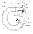
- the two connecting portions 19, 21 disposed closer to the engine 1 are respectively connected to the two branch pipes 12, 13 extending respectively from the second and third cylinders A2, A3 located at the central portion of the cylinder series. More specifically, referring to Figs. 5 and 6, the two branch pipes 12 and 13 are integrally formed at their upper ends with cylindrical engaging protrusions 12a and 13a, respectively. These protrusions 12a, 13a are to be fitted into connecting bores 15a formed in the common flange 15.
- the branch pipes 12 and 13 are integrally formed with flanged portions 12b and 13b, respectively. These flanged portions 12b, 13b are to be fitted into receiving bores 19a and 21b of the respective connecting portions 19 and 21 of the surge tank 10. As seen in Figs. 5 and 6, the central axes of the engaging protrusion 12a (or 13a) and the flanged portion 12b (or 13b) extend perpendicularly to each other.
- the distance S1 between the center of the connecting bore 15a of the common flange 15 and the upper surface 23 of the receiving bore 19a (21a) of the surge tank 10 is made slightly larger than the distance S2 between the center of the engaging protrusion 12a (13a) and the upper surface 22 of the flanged portion 12b (13b).
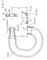
- the other two connecting portions 18, 20 disposed farther from the engine 1 are respectively connected to the other two branch pipes 11, 14 extending respectively from the first and fourth cylinders A1, A4 located at both ends of the cylinder series. More specifically, referring to Figs. 3 and 4, the two branch pipes 11 and 14 are integrally formed at their upper ends with cylindrical engaging protrusions 11a and 14a, respectively. These protrusions 11a, 14a are to be fitted into connecting bores 15a formed in the common flange 15.
- the branch pipes 11 and 14 are integrally formed with flanged portions 11b and 14b, respectively. These flanged portions 11b, 14b are to be fitted into receiving bores 18a and 20b of the respective connecting portions 18 and 20 of the surge tank 10. As seen in Figs. 3 and 4, the central axes of the engaging protrusion 11a (or 14a) and the flanged portion 11b (or 14b) extend perpendicularly to each other.
- the distance S1 between the center of the connecting bore 15a of the common flange 15 and the upper surface 23 of the receiving bore 18a (20a) of the surge tank 10 is made slightly larger than the distance S2 between the center of the engaging protrusion 11a (14a) and the upper surface 22 of the flanged portion 11b (14b).
- the connecting arrangement of the above embodiment is advantageous for the following reasons.
- each of the branch pipes 11-14 needs to extend along a respective bent path for meeting this requirement.
- the two intake ports 5, 6 for the second and third cylinders A2, A3 are located closer to the surge tank 10 than the other two intake ports 4, 7 for the first and fourth cylinders A1, A4, whereas the two connecting portions 19, 21 of the surge tank 10 are located closer to the engine 1 than the other two connecting portions 18, 20.
- the two connecting portions 19, 21 disposed closer to the engine 1 are connected to the two branch pipes 12, 13 extending from the second and third cylinders A2, A3, whereas the other two connecting portions 18, 20 disposed farther from the engine 1 are connected to the other two branch pipes 11, 14 extending from the first and fourth cylinders A1, A4. Therefore, the downwardly extending portions of the two branch pipes 12, 13 shift laterally inward by as much as the two connecting portions 19, 21 are located closer to the engine 1 than the other two connecting portions 18, 20. As a result, the laterally projecting length L of the downwardly extending portions of the two branch pipes 12, 13 is relatively small, thereby realizing compactness of the intake manifold 8 as a whole.
- each of the two branch pipes 11, 14 extending from the first and fourth cylinders A1, A4 must be bent to enter a limited space between the surge tank 10 and a respective one of the other two branch pipes 12, 13 under the surge tank 10.
- the respective axes of the two connecting portions 19, 21 connected to the branch pipes 12, 13 are oriented vertically as shown in Figs. 1 and 2, whereas the respective axes of the other two connecting portions 18, 20 connected to the branch pipes 11, 14 are oriented obliquely at a suitable angle.
- the two connecting portions 18, 20 connected to the branch pipes 11, 14 are inclined to be directed away from each other. Such inclined orientation of the connecting portions 18, 20 is desirable for the following reasons.
- each of the two branch pipes 11, 14 needs to be bent sharply with a small curvature near the surge tank 10 for entering into the limited space between the surge tank 10 and a respective one of the other two branch pipes 12, 13.
- the flow resistance within the branch pipes 11, 14 inevitably increases, consequently providing a hindrance to gas feed.
- a sharp bend of these branch pipes 11, 14 makes a manufacturing process difficult regardless of the fact that they are made of a resin.
- each of the two branch pipes 11, 14 does not need to be bent sharply for entering into the limited space between the surge tank 10 and a respective one of the other two branch pipes 12, 13.
- the flow resistance within the branch pipes 11, 14 may be kept relatively low.
- these branch pipes 11, 14 may be manufactured relatively easily.
- branch pipes 11-14 With respect to the flow resistance within the branch pipes 11-14, it should also be appreciated that these branch pipes are made of a hard resin. In this arrangement, the inner surface of each branch pipe is rendered smooth, whereby the flow resistance within the pipe is advantageously low.
- the intake pipe 9 of the surge tank 10 is provided at a position offset laterally outward from the center of the surge tank 10 (see Figs. 1 and 3). This offset arrangement of the intake pipe 9 is preferable for removably mounting the throttle body 17 to the intake pipe 9 without interfering with the engine 1.
- the intake pipe 9 may be preferably inclined or curved in such a way that its axis is directed toward the general center of the square, rectangle or trapezoid defined by the four connecting portions 18-21 of the surge tank 10.
- Such an orientation of the intake pipe 9 is advantageous for evenly distributing the air-fuel mixture to the four branch pipes 11-14 while also reducing the flow resistance against the air-fuel mixture. If the intake pipe 9 is arranged offset laterally outward but is not inclined or curved in this way, the air-fuel mixture supplied through the intake pipe 9 is unevenly distributed with respect to the four branch pipes 11-14, and a smooth gas flow within the surge tank 10 is hindered to result in an increase of the flow resistance.
- the intake pipe 9 may be preferably flared toward the interior of the surge tank 10 to have a progressively increasing cross section. This flaring configuration of the intake pipe 9 combined with the above-described orientation thereof is additionally advantageous for even distribution of the air-fuel mixture with respect to the different branch pipes 11-14 and for a flow resistance reduction.
- the throttle body 17 (Fig. 2) is further provided with a conduit (not shown) for introducing blow-by gas from the cylinder head 2 of the engine 1 or purging air from a canister (not shown) at a position downstream from the non-illustrated throttle valve.
- Figs. 7-10 for illustrating a method for connecting the lower ends of the respective branch pipes 11-14 to the connecting portions 18-21 of the surge tank 10.
- a heat-sealing method may conveniently be utilized.
- the lower ends 11b-14b of the branch pipes 11-14 are formed into flat end surfaces 22 so that these flat end surfaces are perpendicular to the axial lines of the lower ends 11b-14b.
- receiving bores 18a-21a are formed at the connecting portions 18-21 of the surge tank 10.
- Each of the receiving bores 18a-21a is provided with a connecting surface 23 and with a circular protruding portion 24.
- a heating wire 25 is put in each of the receiving bores 18a-21a so that the wire passes around the protruding portion 24. Then, the heating wire 25 is held between the end surface 22 and the connecting surface 23, as shown in Figs. 7 and 8. With the heating wire 25 thus provided, the branch pipes 11-14 are pressed against the surge tank 10. In this state, a suitable voltage is applied across the heating wire 25 for generating heat.
- the protruding portions 24 are formed on the surge tank 10.
- those protrusions may be formed on the branch pipes 11-14, or on both the surge tank 10 and the branch pipes 11-14.
- the surge tank 10 may additionally be provided with a sealing ring member 26 located between the heating wire 25 and the protruding portion 24.
- the ring member 26, which may be made of an elastic soft material, is partially embedded in the surge tank 10, as illustrated.
- the branch pipes 11-14 are pressed against the surge tank 10, while a predetermined voltage is being applied across the heating wire 25.
- the upper ends of the branch pipes 11-14 are formed with cylindrical engaging protrusions 11a-14a which are fitted into the connecting bores 15a of the common flange 15.
- the common flange 15 has a connecting surface 15b to be attached to the longitudinal side surface 3 of the cylinder head 2.
- the common flange 15 has an obverse surface 15c.
- the common flange 15 is formed with circular hollow portions 27 each of which is coaxial with a respective one of the connecting bores 15a.
- a sealing member 28 which may be made of an elastic material such as rubber, is fitted into each hollow portion 27.
- the sealing member 28 has an axial dimension greater than that of the hollow portion 27.
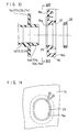
- the branch pipes 11-14 are previously formed with cylindrical engaging protrusions 11a-14a. Together with these protrusions 11a-14a, the respective branch pipes 11-14 are also formed with brims 11c-14c which are integrally connected to the protrusions 11a-14a, respectively. As shown in Fig. 16, when the branch pipes 11-14 are properly attached to the common flange 15, the brims 11c-14c come into close contact with the obverse surface 15c of the common flange 15. Such an arrangement is advantageous for enabling accurate positioning of the branch pipes 11-14 with respect to the common flange 15.
- heating wires 29 are arranged on the obverse surface 15c so that each heating wire 29 surrounds a corresponding one of the connecting bores 15a (see also Fig. 14).
- each heating wire 29 is arranged circumferentially of the corresponding one of the connecting bores 15a.
- the engaging protrusions 11a-14a are inserted into the connecting bores 15a of the common flange 15.
- the branch pipes 11-14 can be firmly connected to the common flange 15. Further, since the heat sealing by using the heating wires 29 is performed outside of the engaging protrusions 11a-14a, melted resin will not flow into the branch pipes 11-14.
- the branch pipes 11-14 are advantageously attached to the common flange 15 by heat-sealing.
- the intake manifold 8 is connected to the cylinder head 2 of the four-cylinder internal combustion engine 1.
- the present invention is not limited to such an embodiment.
- the present invention may be applied to a three-cylinder internal combustion engine in which case the underside of a surge tank has three connecting portions located at the respective corners of an equilateral triangle with one side extending in parallel to the longitudinal axis of the cylinder head, or to a six-cylinder internal combustion engine in which case the underside of a surge tank has six connecting portions located at the respective corners of an equilateral hexagon with one side extending in parallel to the longitudinal axis of the cylinder head.
Landscapes
- Engineering & Computer Science (AREA)
- Mechanical Engineering (AREA)
- General Engineering & Computer Science (AREA)
- Chemical & Material Sciences (AREA)
- Combustion & Propulsion (AREA)
- Manufacturing & Machinery (AREA)
- Physics & Mathematics (AREA)
- Geometry (AREA)
- Characterised By The Charging Evacuation (AREA)
- Lining Or Joining Of Plastics Or The Like (AREA)
Applications Claiming Priority (11)
| Application Number | Priority Date | Filing Date | Title |
|---|---|---|---|
| JP24684298 | 1998-09-01 | ||
| JP24684398 | 1998-09-01 | ||
| JP24684698A JP3618555B2 (ja) | 1998-09-01 | 1998-09-01 | 慣性過給式吸気マニホールドにおけるブランチパイプの接合方法 |
| JP24684498A JP3177501B2 (ja) | 1998-09-01 | 1998-09-01 | 多気筒内燃機関における慣性過給式吸気マニホールドの構造 |
| JP24684598 | 1998-09-01 | ||
| JP24684498 | 1998-09-01 | ||
| JP24684698 | 1998-09-01 | ||
| JP24684598A JP2000073891A (ja) | 1998-09-01 | 1998-09-01 | 慣性過給式吸気マニホールドにおけるブランチパイプの接合方法 |
| JP24684298A JP3177499B2 (ja) | 1998-09-01 | 1998-09-01 | 多気筒内燃機関における慣性過給式吸気マニホールドの構造 |
| JP24684398A JP3177500B2 (ja) | 1998-09-01 | 1998-09-01 | 多気筒内燃機関における慣性過給式吸気マニホールドの構造 |
| EP19990117000 EP0984156B1 (fr) | 1998-09-01 | 1999-08-28 | Collecteur d'admission du type à résonance pour moteur à plusieurs cylindres |
Related Parent Applications (1)
| Application Number | Title | Priority Date | Filing Date |
|---|---|---|---|
| EP19990117000 Division EP0984156B1 (fr) | 1998-09-01 | 1999-08-28 | Collecteur d'admission du type à résonance pour moteur à plusieurs cylindres |
Publications (3)
| Publication Number | Publication Date |
|---|---|
| EP1452721A2 true EP1452721A2 (fr) | 2004-09-01 |
| EP1452721A3 EP1452721A3 (fr) | 2004-12-29 |
| EP1452721B1 EP1452721B1 (fr) | 2008-10-08 |
Family
ID=27530137
Family Applications (2)
| Application Number | Title | Priority Date | Filing Date |
|---|---|---|---|
| EP20040013423 Expired - Lifetime EP1452721B1 (fr) | 1998-09-01 | 1999-08-28 | Procédé de connection des tuyaux d'embrêchements d'un collecteur d'admission |
| EP19990117000 Expired - Lifetime EP0984156B1 (fr) | 1998-09-01 | 1999-08-28 | Collecteur d'admission du type à résonance pour moteur à plusieurs cylindres |
Family Applications After (1)
| Application Number | Title | Priority Date | Filing Date |
|---|---|---|---|
| EP19990117000 Expired - Lifetime EP0984156B1 (fr) | 1998-09-01 | 1999-08-28 | Collecteur d'admission du type à résonance pour moteur à plusieurs cylindres |
Country Status (4)
| Country | Link |
|---|---|
| US (2) | US6283078B1 (fr) |
| EP (2) | EP1452721B1 (fr) |
| KR (1) | KR100331454B1 (fr) |
| DE (2) | DE69934059T2 (fr) |
Families Citing this family (21)
| Publication number | Priority date | Publication date | Assignee | Title |
|---|---|---|---|---|
| DE19909850A1 (de) * | 1999-03-08 | 2000-09-14 | Mahle Filtersysteme Gmbh | Sauganlage für eine Brennkraftmaschine |
| JP3888030B2 (ja) * | 2000-05-31 | 2007-02-28 | スズキ株式会社 | 船外機のインテークマニフォールド |
| US6427655B2 (en) * | 2000-05-31 | 2002-08-06 | Suzuki Kabushiki Kaisha | Intake manifold of outboard motor |
| JP3585818B2 (ja) | 2000-09-12 | 2004-11-04 | 本田技研工業株式会社 | 吸気マニホールド |
| JP3530481B2 (ja) * | 2000-10-31 | 2004-05-24 | ジー・ピー・ダイキョー株式会社 | 樹脂製インテークマニホールド、及びその製造方法 |
| DE60114125T2 (de) * | 2000-12-01 | 2006-07-06 | Denso Corp., Kariya | Ansaugvorrichtung zum gebrauch bei einer brennkraftmaschine |
| EP1277947B1 (fr) * | 2001-07-20 | 2007-02-28 | Mann + Hummel GmbH | Dispositif de fixation pour un collecteur d'admission |
| US6695853B2 (en) | 2001-11-21 | 2004-02-24 | Emed, Inc. | Microdermabrasion system and method of use |
| US7066129B2 (en) * | 2003-10-06 | 2006-06-27 | General Motors Corporation | Intake manifold and runner apparatus |
| FR2877997B1 (fr) * | 2004-11-17 | 2007-01-05 | Renault Sas | Systeme de fixation d'un conduit d'acheminement d'air vers un filtre a air |
| DE102004061505B4 (de) * | 2004-12-21 | 2021-08-26 | Volkswagen Ag | Brennkraftmaschine für ein Kraftfahrzeug |
| US7387099B2 (en) * | 2005-05-11 | 2008-06-17 | Diaphorm Technologies Llc | Thermoplastic composite intake manifold |
| US8236008B2 (en) | 2008-02-29 | 2012-08-07 | Envy Medical, Inc. | Microdermabrasion treatment heads |
| US8945104B2 (en) | 2008-08-22 | 2015-02-03 | Envy Medical, Inc. | Microdermabrasion system with combination skin therapies |
| US20110277716A1 (en) * | 2010-05-17 | 2011-11-17 | Gm Global Technology Operations, Inc. | Intake Manifold for an Internal Combustion Engine |
| CN103370527B (zh) | 2010-12-22 | 2017-07-14 | 提克纳有限责任公司 | 具有复杂三维构造的高温导管 |
| CZ304415B6 (cs) * | 2011-12-06 | 2014-04-23 | Fakulta Strojní, Výzkumné Centrum Spalovacích Motorů A Automobilů Josefa Božka | Zařízení pro zvyšování intenzity víření protékajících médií, zejména v sacím potrubí spalovacích motorů |
| JP5870900B2 (ja) * | 2012-10-31 | 2016-03-01 | トヨタ自動車株式会社 | 吸気マニホールド |
| FR3058460B1 (fr) * | 2016-11-08 | 2018-11-09 | Safran Aircraft Engines | Ensemble de raccordement pour le refroidissement d'une turbine de turbomachine |
| KR20220003225A (ko) * | 2020-07-01 | 2022-01-10 | 현대자동차주식회사 | 흡기 매니폴드 및 이를 포함하는 엔진 |
| JP7746904B2 (ja) * | 2022-04-01 | 2025-10-01 | マツダ株式会社 | エンジンの吸気装置 |
Citations (1)
| Publication number | Priority date | Publication date | Assignee | Title |
|---|---|---|---|---|
| JPH0199965U (fr) | 1987-12-23 | 1989-07-05 |
Family Cites Families (47)
| Publication number | Priority date | Publication date | Assignee | Title |
|---|---|---|---|---|
| DE1704186A1 (de) * | 1968-02-23 | 1971-05-19 | Wilfried Leitz | Verfahren zum Herstellen von Tuben |
| DE3119190A1 (de) * | 1981-05-14 | 1982-12-16 | Klöckner-Humboldt-Deutz AG, 5000 Köln | Ansaugsystem mit schwingrohren |
| US4501235A (en) * | 1983-04-04 | 1985-02-26 | Ford Motor Company | Tuned engine intake manifold |
| JPS60159036A (ja) * | 1984-01-31 | 1985-08-20 | Suzuki Motor Co Ltd | 中空樹脂体の補強装置 |
| US4829944A (en) * | 1986-06-25 | 1989-05-16 | Showa Aluminum Corporation | Intake manifold and process for producing same |
| JPH0739147B2 (ja) | 1986-12-19 | 1995-05-01 | 日産自動車株式会社 | 樹脂製インテ−クマニホ−ルド |
| JP2632873B2 (ja) | 1987-10-13 | 1997-07-23 | 日本特許管理株式会社 | ジッパー付袋における開口維持装置 |
| DE3742057C1 (de) * | 1987-12-11 | 1988-09-22 | Porsche Ag | Ansauganlage fuer eine mehrzylindrige Brennkraftmaschine |
| JPH0354317A (ja) | 1989-07-21 | 1991-03-08 | Yamaha Motor Co Ltd | エンジンの吸気装置 |
| JPH0791983B2 (ja) * | 1989-09-05 | 1995-10-09 | マツダ株式会社 | 多気筒エンジンの吸気装置 |
| US5094194A (en) * | 1989-11-06 | 1992-03-10 | General Motors Corporation | Integrated induction system |
| US5144918A (en) * | 1990-07-19 | 1992-09-08 | Mazda Motor Corporation | Intake system for engine |
| GB2256675A (en) * | 1991-06-11 | 1992-12-16 | Ford Motor Co | Tuned i.c.engine intake system. |
| JPH0510220A (ja) | 1991-07-02 | 1993-01-19 | Showa Alum Corp | 吸気マニホルド |
| CA2073935C (fr) | 1992-05-01 | 2000-10-17 | Changize Sadr | Methode de moulage de collecteur pour vehicule automobile |
| JPH068756A (ja) | 1992-06-26 | 1994-01-18 | Nissan Motor Co Ltd | 車両用駆動力制御装置 |
| FR2697293B1 (fr) * | 1992-10-26 | 1994-11-10 | Solex | Dispositif d'alimentation à tubulure intégrée. |
| DE4316430A1 (de) | 1993-05-17 | 1994-11-24 | Bayer Ag | Substituierte Triazolinone |
| JPH06341355A (ja) | 1993-06-02 | 1994-12-13 | Aisin Takaoka Ltd | 吸気マニホールド |
| JP2989429B2 (ja) | 1993-07-16 | 1999-12-13 | 財団法人神奈川科学技術アカデミー | 細胞診断用合成マーカー |
| US5400951A (en) * | 1993-08-31 | 1995-03-28 | Showa Aluminum Corporation | Method of brazing a joint portion of an intake manifold with preplaced brazing |
| JPH07148864A (ja) | 1993-12-01 | 1995-06-13 | Asahi Tec Corp | 合成樹脂製マニホールドの製造方法 |
| US5538571A (en) * | 1993-12-01 | 1996-07-23 | Asahi Tec Corporation | Method of manufacturing hollow resin molding |
| US5636605A (en) * | 1994-06-22 | 1997-06-10 | Toyota Jidosha K.K. | Composite intake manifold for an internal combustion engine |
| JPH0849610A (ja) | 1994-08-04 | 1996-02-20 | Toyota Motor Corp | 内燃機関の樹脂製マニホールド |
| DE4432199A1 (de) * | 1994-09-09 | 1996-03-14 | Wilhelm Hegler | Verfahren zum Verbinden eines Kunststoff-Rohres mit einer Kunststoff-Muffe |
| JP3210825B2 (ja) * | 1995-01-14 | 2001-09-25 | ヤマハ発動機株式会社 | V型多気筒エンジンの吸気装置 |
| US5575247A (en) * | 1995-02-01 | 1996-11-19 | Nippondenso Co., Ltd. | Air intake device for an internal combustion engine |
| US5551387A (en) * | 1995-02-24 | 1996-09-03 | Ortech Corporation | Tuned intake manifold for OTTO cycle engines |
| JP2699915B2 (ja) * | 1995-03-13 | 1998-01-19 | トヨタ自動車株式会社 | 吸気マニホールド |
| JPH08277717A (ja) * | 1995-04-06 | 1996-10-22 | Du Pont Kk | 吸気制御バルブを備えた樹脂吸気系 |
| JPH08334195A (ja) | 1995-06-07 | 1996-12-17 | Mitsubishi Plastics Ind Ltd | 栓体を内蔵した電気融着継手 |
| DE19521025A1 (de) * | 1995-06-13 | 1996-12-19 | Mann & Hummel Filter | Rohrmodul |
| DE19523870A1 (de) * | 1995-06-30 | 1997-01-02 | Mann & Hummel Filter | Ansaugeinrichtung aus thermoplastischem Kunststoff |
| DE19528047A1 (de) * | 1995-07-31 | 1997-02-06 | Bosch Gmbh Robert | Brennkraftmaschine mit einem daran befestigten Saugmodul bzw. Saugrohr und Verfahren zur Befestigung eines Saugmoduls bzw. Saugrohrs an einer Brennkraftmaschine |
| FR2739898B1 (fr) * | 1995-10-11 | 1997-12-12 | Coutier Moulage Gen Ind | Procede de fabrication d'un collecteur d'admission d'air pour moteur a explosion et collecteur d'admission d'air obtenu selon ce procede. |
| JPH09144977A (ja) | 1995-11-27 | 1997-06-03 | Tokyo Gas Co Ltd | 電気融着管継手 |
| JPH09250408A (ja) | 1996-03-14 | 1997-09-22 | Toyota Motor Corp | 内燃機関の吸気装置における吸気管配設構造 |
| IT1285682B1 (it) * | 1996-04-22 | 1998-06-18 | Magneti Marelli Spa | Gruppo integrato di adduzione di carburante e comburente |
| JP3202920B2 (ja) | 1996-07-03 | 2001-08-27 | ダイハツ工業株式会社 | 合成樹脂製管状体の製造方法およびその装置並びに合成樹脂製インテークマニホールド |
| JPH1068492A (ja) | 1996-08-27 | 1998-03-10 | Mitsubishi Plastics Ind Ltd | 電気融着式分岐サドル継手 |
| DE19648273A1 (de) * | 1996-11-21 | 1998-05-28 | Basf Ag | Hohlformkörper und Verfahren zum Verbinden von Formteilen |
| EP0892169B1 (fr) | 1996-11-22 | 2002-06-12 | Denso Corporation | Dispositif d'admission d'un moteur a combustion interne |
| US6089202A (en) * | 1997-08-21 | 2000-07-18 | Denso Corporation | Air-supply module for internal combustion engine |
| JPH11107870A (ja) * | 1997-10-07 | 1999-04-20 | Daihatsu Motor Co Ltd | インテークマニホールド |
| JP3601299B2 (ja) * | 1998-05-30 | 2004-12-15 | スズキ株式会社 | 内燃機関の吸気構造 |
| JP3394192B2 (ja) * | 1998-09-01 | 2003-04-07 | ジー・ピー・ダイキョー株式会社 | 合成樹脂製インテークマニホールド及びその製造方法 |
-
1999
- 1999-08-27 KR KR1019990035803A patent/KR100331454B1/ko not_active Expired - Fee Related
- 1999-08-28 DE DE1999634059 patent/DE69934059T2/de not_active Expired - Lifetime
- 1999-08-28 EP EP20040013423 patent/EP1452721B1/fr not_active Expired - Lifetime
- 1999-08-28 DE DE69939713T patent/DE69939713D1/de not_active Expired - Lifetime
- 1999-08-28 EP EP19990117000 patent/EP0984156B1/fr not_active Expired - Lifetime
- 1999-08-31 US US09/386,445 patent/US6283078B1/en not_active Expired - Lifetime
-
2001
- 2001-07-20 US US09/908,812 patent/US6371070B2/en not_active Expired - Lifetime
Patent Citations (1)
| Publication number | Priority date | Publication date | Assignee | Title |
|---|---|---|---|---|
| JPH0199965U (fr) | 1987-12-23 | 1989-07-05 |
Also Published As
| Publication number | Publication date |
|---|---|
| DE69939713D1 (de) | 2008-11-20 |
| EP1452721B1 (fr) | 2008-10-08 |
| US6371070B2 (en) | 2002-04-16 |
| US20010042531A1 (en) | 2001-11-22 |
| EP1452721A3 (fr) | 2004-12-29 |
| KR100331454B1 (ko) | 2002-04-09 |
| EP0984156A3 (fr) | 2001-01-31 |
| KR20000022767A (ko) | 2000-04-25 |
| EP0984156A2 (fr) | 2000-03-08 |
| EP0984156B1 (fr) | 2006-11-22 |
| DE69934059T2 (de) | 2007-06-28 |
| US6283078B1 (en) | 2001-09-04 |
| DE69934059D1 (de) | 2007-01-04 |
Similar Documents
| Publication | Publication Date | Title |
|---|---|---|
| EP1452721A2 (fr) | Procédé de connection des tuyaux d'embrêchements d'un collecteur d'admission | |
| US4829944A (en) | Intake manifold and process for producing same | |
| JPH0622140Y2 (ja) | フユーエルデリバリパイプ | |
| JP4965513B2 (ja) | インテークマニホールド | |
| JP4034104B2 (ja) | 燃料タンクへの遮熱板取付け構造 | |
| US20040159298A1 (en) | Intake system and method for producing the same | |
| JP3352572B2 (ja) | 多気筒内燃機関における吸気装置 | |
| JP4846616B2 (ja) | クランプ付ホースアッセンブリおよびバンドホルダ | |
| US4996962A (en) | Fuel delivery rail assembly | |
| US20140261279A1 (en) | Intake manifold for internal combustion engine | |
| EP3181886B1 (fr) | Collecteur d'admission | |
| CA2251363A1 (fr) | Systeme d'admission pour moteur a combustion interne | |
| US7128055B2 (en) | Fuel injector clocking feature | |
| EP0939211A2 (fr) | Collecteur d'admission du type à résonance pour moteur à plusieurs cylindres | |
| US5743011A (en) | Process of manufacturing vehicle manifolds | |
| JP7343309B2 (ja) | 自動車用内燃機関の燃料デリバリ装置 | |
| JP2009074509A (ja) | インテークマニホールド | |
| JP3618555B2 (ja) | 慣性過給式吸気マニホールドにおけるブランチパイプの接合方法 | |
| JP3177501B2 (ja) | 多気筒内燃機関における慣性過給式吸気マニホールドの構造 | |
| JP5752605B2 (ja) | 過給機付きエンジンにおけるスロットルボディの取付け構造 | |
| JPH07253018A (ja) | 内燃機関のマニホールド接続構造 | |
| JP3342316B2 (ja) | 多気筒内燃機関における慣性過給式吸気装置 | |
| JP3177500B2 (ja) | 多気筒内燃機関における慣性過給式吸気マニホールドの構造 | |
| JP2000073891A (ja) | 慣性過給式吸気マニホールドにおけるブランチパイプの接合方法 | |
| JPH09264211A (ja) | 内燃機関の吸気構造 |
Legal Events
| Date | Code | Title | Description |
|---|---|---|---|
| PUAI | Public reference made under article 153(3) epc to a published international application that has entered the european phase |
Free format text: ORIGINAL CODE: 0009012 |
|
| 17P | Request for examination filed |
Effective date: 20040608 |
|
| AC | Divisional application: reference to earlier application |
Ref document number: 0984156 Country of ref document: EP Kind code of ref document: P |
|
| AK | Designated contracting states |
Kind code of ref document: A2 Designated state(s): DE FR GB |
|
| PUAL | Search report despatched |
Free format text: ORIGINAL CODE: 0009013 |
|
| RIC1 | Information provided on ipc code assigned before grant |
Ipc: 7F 02M 35/10 B Ipc: 7F 02M 35/104 A |
|
| AK | Designated contracting states |
Kind code of ref document: A3 Designated state(s): DE FR GB |
|
| AKX | Designation fees paid |
Designated state(s): DE FR GB |
|
| 17Q | First examination report despatched |
Effective date: 20060306 |
|
| RAP1 | Party data changed (applicant data changed or rights of an application transferred) |
Owner name: TOYOTA MOTOR CORPORATION Owner name: DAIKYONISHIKAWA CORPORATION Owner name: DAIHATSU MOTOR CO., LTD. |
|
| GRAP | Despatch of communication of intention to grant a patent |
Free format text: ORIGINAL CODE: EPIDOSNIGR1 |
|
| GRAS | Grant fee paid |
Free format text: ORIGINAL CODE: EPIDOSNIGR3 |
|
| GRAA | (expected) grant |
Free format text: ORIGINAL CODE: 0009210 |
|
| AC | Divisional application: reference to earlier application |
Ref document number: 0984156 Country of ref document: EP Kind code of ref document: P |
|
| AK | Designated contracting states |
Kind code of ref document: B1 Designated state(s): DE FR GB |
|
| REG | Reference to a national code |
Ref country code: GB Ref legal event code: FG4D |
|
| REF | Corresponds to: |
Ref document number: 69939713 Country of ref document: DE Date of ref document: 20081120 Kind code of ref document: P |
|
| PLBE | No opposition filed within time limit |
Free format text: ORIGINAL CODE: 0009261 |
|
| STAA | Information on the status of an ep patent application or granted ep patent |
Free format text: STATUS: NO OPPOSITION FILED WITHIN TIME LIMIT |
|
| 26N | No opposition filed |
Effective date: 20090709 |
|
| REG | Reference to a national code |
Ref country code: GB Ref legal event code: 746 Effective date: 20100406 |
|
| PGFP | Annual fee paid to national office [announced via postgrant information from national office to epo] |
Ref country code: DE Payment date: 20140821 Year of fee payment: 16 |
|
| PGFP | Annual fee paid to national office [announced via postgrant information from national office to epo] |
Ref country code: GB Payment date: 20140827 Year of fee payment: 16 Ref country code: FR Payment date: 20140808 Year of fee payment: 16 |
|
| REG | Reference to a national code |
Ref country code: DE Ref legal event code: R119 Ref document number: 69939713 Country of ref document: DE |
|
| GBPC | Gb: european patent ceased through non-payment of renewal fee |
Effective date: 20150828 |
|
| REG | Reference to a national code |
Ref country code: FR Ref legal event code: ST Effective date: 20160429 |
|
| PG25 | Lapsed in a contracting state [announced via postgrant information from national office to epo] |
Ref country code: DE Free format text: LAPSE BECAUSE OF NON-PAYMENT OF DUE FEES Effective date: 20160301 Ref country code: GB Free format text: LAPSE BECAUSE OF NON-PAYMENT OF DUE FEES Effective date: 20150828 |
|
| PG25 | Lapsed in a contracting state [announced via postgrant information from national office to epo] |
Ref country code: FR Free format text: LAPSE BECAUSE OF NON-PAYMENT OF DUE FEES Effective date: 20150831 |