EP1452861A2 - Appareil pour détecter la concentration de gaz - Google Patents
Appareil pour détecter la concentration de gaz Download PDFInfo
- Publication number
- EP1452861A2 EP1452861A2 EP04001971A EP04001971A EP1452861A2 EP 1452861 A2 EP1452861 A2 EP 1452861A2 EP 04001971 A EP04001971 A EP 04001971A EP 04001971 A EP04001971 A EP 04001971A EP 1452861 A2 EP1452861 A2 EP 1452861A2
- Authority
- EP
- European Patent Office
- Prior art keywords
- applied voltage
- voltage
- characteristic
- fuel ratio
- current
- Prior art date
- Legal status (The legal status is an assumption and is not a legal conclusion. Google has not performed a legal analysis and makes no representation as to the accuracy of the status listed.)
- Ceased
Links
- 238000001514 detection method Methods 0.000 claims abstract description 164
- 239000000446 fuel Substances 0.000 claims abstract description 158
- 239000007784 solid electrolyte Substances 0.000 claims abstract description 34
- 239000007789 gas Substances 0.000 claims description 216
- QVGXLLKOCUKJST-UHFFFAOYSA-N atomic oxygen Chemical compound [O] QVGXLLKOCUKJST-UHFFFAOYSA-N 0.000 claims description 60
- 229910052760 oxygen Inorganic materials 0.000 claims description 60
- 239000001301 oxygen Substances 0.000 claims description 60
- XLYOFNOQVPJJNP-UHFFFAOYSA-N water Substances O XLYOFNOQVPJJNP-UHFFFAOYSA-N 0.000 claims description 39
- 238000002485 combustion reaction Methods 0.000 claims description 38
- 238000000354 decomposition reaction Methods 0.000 claims description 31
- 230000001965 increasing effect Effects 0.000 claims description 22
- 230000008859 change Effects 0.000 claims description 13
- 230000006866 deterioration Effects 0.000 claims description 8
- 230000001105 regulatory effect Effects 0.000 claims description 8
- 230000001276 controlling effect Effects 0.000 claims description 4
- 230000003111 delayed effect Effects 0.000 claims description 4
- 238000009792 diffusion process Methods 0.000 abstract description 9
- 239000010410 layer Substances 0.000 description 33
- MCMNRKCIXSYSNV-UHFFFAOYSA-N Zirconium dioxide Chemical compound O=[Zr]=O MCMNRKCIXSYSNV-UHFFFAOYSA-N 0.000 description 18
- 238000010276 construction Methods 0.000 description 11
- 101100537098 Mus musculus Alyref gene Proteins 0.000 description 9
- 101150095908 apex1 gene Proteins 0.000 description 9
- 230000010355 oscillation Effects 0.000 description 9
- 238000000034 method Methods 0.000 description 8
- 238000012544 monitoring process Methods 0.000 description 8
- 238000006243 chemical reaction Methods 0.000 description 7
- 230000007423 decrease Effects 0.000 description 6
- 230000006872 improvement Effects 0.000 description 6
- BASFCYQUMIYNBI-UHFFFAOYSA-N platinum Chemical compound [Pt] BASFCYQUMIYNBI-UHFFFAOYSA-N 0.000 description 6
- 230000033228 biological regulation Effects 0.000 description 5
- 238000010586 diagram Methods 0.000 description 5
- 230000002708 enhancing effect Effects 0.000 description 4
- ATUOYWHBWRKTHZ-UHFFFAOYSA-N Propane Chemical compound CCC ATUOYWHBWRKTHZ-UHFFFAOYSA-N 0.000 description 3
- 101100269674 Mus musculus Alyref2 gene Proteins 0.000 description 2
- NINIDFKCEFEMDL-UHFFFAOYSA-N Sulfur Chemical compound [S] NINIDFKCEFEMDL-UHFFFAOYSA-N 0.000 description 2
- 230000005856 abnormality Effects 0.000 description 2
- PNEYBMLMFCGWSK-UHFFFAOYSA-N aluminium oxide Inorganic materials [O-2].[O-2].[O-2].[Al+3].[Al+3] PNEYBMLMFCGWSK-UHFFFAOYSA-N 0.000 description 2
- 230000003321 amplification Effects 0.000 description 2
- 239000003990 capacitor Substances 0.000 description 2
- 230000015556 catabolic process Effects 0.000 description 2
- 239000003054 catalyst Substances 0.000 description 2
- 238000006555 catalytic reaction Methods 0.000 description 2
- 239000000919 ceramic Substances 0.000 description 2
- 230000010485 coping Effects 0.000 description 2
- 238000010438 heat treatment Methods 0.000 description 2
- 230000007774 longterm Effects 0.000 description 2
- 238000003199 nucleic acid amplification method Methods 0.000 description 2
- 229910052697 platinum Inorganic materials 0.000 description 2
- 231100000572 poisoning Toxicity 0.000 description 2
- 230000000607 poisoning effect Effects 0.000 description 2
- 230000009467 reduction Effects 0.000 description 2
- 230000008929 regeneration Effects 0.000 description 2
- 238000011069 regeneration method Methods 0.000 description 2
- 229910052717 sulfur Inorganic materials 0.000 description 2
- 239000011593 sulfur Substances 0.000 description 2
- 230000002411 adverse Effects 0.000 description 1
- 238000013459 approach Methods 0.000 description 1
- 230000008901 benefit Effects 0.000 description 1
- 230000005540 biological transmission Effects 0.000 description 1
- 230000015572 biosynthetic process Effects 0.000 description 1
- 150000001875 compounds Chemical class 0.000 description 1
- 230000006735 deficit Effects 0.000 description 1
- 230000001934 delay Effects 0.000 description 1
- 230000008021 deposition Effects 0.000 description 1
- 230000000694 effects Effects 0.000 description 1
- 230000020169 heat generation Effects 0.000 description 1
- 230000005764 inhibitory process Effects 0.000 description 1
- 238000012986 modification Methods 0.000 description 1
- 230000004048 modification Effects 0.000 description 1
- 230000035699 permeability Effects 0.000 description 1
- 239000011148 porous material Substances 0.000 description 1
- 239000001294 propane Substances 0.000 description 1
- 239000011241 protective layer Substances 0.000 description 1
- 230000006641 stabilisation Effects 0.000 description 1
- 238000011105 stabilization Methods 0.000 description 1
Images




Classifications
-
- G—PHYSICS
- G01—MEASURING; TESTING
- G01N—INVESTIGATING OR ANALYSING MATERIALS BY DETERMINING THEIR CHEMICAL OR PHYSICAL PROPERTIES
- G01N27/00—Investigating or analysing materials by the use of electric, electrochemical, or magnetic means
- G01N27/26—Investigating or analysing materials by the use of electric, electrochemical, or magnetic means by investigating electrochemical variables; by using electrolysis or electrophoresis
- G01N27/403—Cells and electrode assemblies
- G01N27/406—Cells and probes with solid electrolytes
- G01N27/407—Cells and probes with solid electrolytes for investigating or analysing gases
- G01N27/4071—Cells and probes with solid electrolytes for investigating or analysing gases using sensor elements of laminated structure
Definitions
- the present invention relates to a gas concentration detecting apparatus designed to detect a specific component concentration in a gas to be detected (which will hereinafter be referred to equally as a "detection gas").
- the A/F sensor includes a sensor element composed of a solid electrolyte and a pair of electrodes provided on the solid electrolyte, and it is made to generate a flow of an element current corresponding to an oxygen concentration whenever a voltage is applied to the sensor element.
- FIG. 3 is an illustration of an output characteristic of this A/F sensor. As seen from FIG.
- a flat region parallel with a voltage axis i.e., a limiting current region in which an element current Ip (limiting current) becomes constant, appears and this limiting current region shifts generally to a high-voltage side as the oxygen concentration increases.
- the oscillation of the applied voltage Vp occurs, for example, due to the facts that the applied voltage characteristic provides a positive feedback so that the applied voltage Vp increases with an increase in the element current Ip and that, if a radio-frequency component such as noise is introduced into the sensor, an impedance characteristic peculiar to the sensor varies the impedance value to increase the gain of the sensor element.
- the enhancement of the exhaust gas regulations or abnormality detection regulations (OBD and others) on vehicles requires the expansion of the lean side of the air-fuel ratio detection range up to the atmospheric state.
- the importance is on the increase in that, in terms of an NOx occlusion reduction type catalyst provided in an exhaust system, the rich combustion control is implemented with high accuracy to achieve the restoration of the NOx occlusion ability, the sulfur poisoning regeneration and others, and for the purpose of improving the fuel consumption, the rich combustion control at a high engine load is executed with high accuracy.
- a strong request exists in that the air-fuel ratio detection range is enlarged to enable the air-fuel ratio detection over a wide range and the air-fuel ratio detection accuracy is increased in this detection range.
- the present invention has been developed in consideration of these situations, and it is therefore an object of the invention to provide a gas concentration detecting apparatus capable of implementing the applied voltage control with high accuracy to improve the gas concentration detection accuracy over a wide range.
- a gas concentration detecting apparatus for use in a limit-current type gas concentration sensor.
- an element current (limiting current) corresponding to a specific component concentration flows whenever a voltage is applied to a sensor element.
- the applied voltage is controlled on the basis of an applied voltage characteristic defined linearly, and the specific component concentration in a gas to be detected over a wide range on the basis of a limiting current output of the gas concentration sensor.
- the applied voltage characteristic is set on the basis of a width of a limiting current region for each concentration level.
- an applied voltage can be set in the exterior of a limiting current region in controlling the applied voltage on the basis of the applied voltage characteristic (applied voltage characteristic defining the relationship between a sensor applied voltage and an element current) defined linearly (primary-linearly).
- the applied voltage characteristic applied voltage characteristic defining the relationship between a sensor applied voltage and an element current
- the inventors have confirmed that the width of a limiting current region (width on a voltage axis) stands at a different value according to a concentration level and, hence, set an applied voltage characteristic on the basis of the width of a limiting current region on each concentration level. Accordingly, even if the gas concentration varies in a wide gas concentration detection range, the applied voltage is not set in a state deviated from the limiting current region. In consequence, the applied voltage control can be implemented with high accuracy, thus achieving the improvement of the gas concentration detection accuracy over a wide range.
- an applied voltage control unit and an element current detection unit are connected to an electrode of the sensor element, and the applied voltage control unit controls the applied voltage on the basis of the applied voltage characteristic defined linearly, and the element current detection unit detects an element current output corresponding to the specific component concentration of a gas to be detected in the gas concentration detection range set widely.
- the applied voltage characteristic is set on the basis of the width of the limiting current region on each concentration level in the gas concentration detection range.
- the applied voltage is not set out of the limiting current region.
- the applied voltage control can be implemented with high accuracy, thus achieving the improvement of the gas concentration detection accuracy over a wide range.
- an upper limit or one point on the limiting current region in the vicinity of the upper limit in the gas concentration detection range is specified and a lower limit or one point on the limiting current region in the vicinity of the lower limit in the gas concentration detection range is specified, with an applied voltage line serving as the applied voltage characteristic being set to pass through (cross) these points specified.
- the gas concentration detection range is divided into a plurality of portions, and an upper limit or one point on the limiting current region in the vicinity of the upper limit in each detection range portion is specified and a lower limit or one point on the limiting current region in the vicinity of the lower limit in each detection range portion is specified, with the applied voltage line serving as the applied voltage characteristic being set to pass through these points specified.
- the applied voltage lines can be set so as to surely pass through the limiting current region in a wide gas concentration detection range.
- the current variation quantity is regulated to determine the limiting current region, and the applied voltage characteristic is set to pass through an intermediate point of this limiting current region. This can remove the influence of the reaction of components other than the specific component, thereby implementing the applied voltage control appropriately.
- V-I characteristic When the sensor output characteristic (V-I characteristic) is analyzed in detail, there exist a point at which the element current starts to become constant with a rise of the applied voltage in a state where a balance is made between the applied voltage and the electromotive force of the sensor element while the gas diffusion is restricted and a point at which, in addition to a specific component, water in the gas is decomposed and the element current starts to increase due to the water decomposition. Therefore, according to a further aspect of the present invention, when the applied voltage to the sensor element is increased, a limiting current region is set between a first voltage point at which the output of an electromotive force accomplishing a balance with the applied voltage starts and a second voltage point at which the decomposition of water contained in a gas to be detected starts.
- the limiting current region is set between a first voltage point at which, when the applied voltage to the sensor element is increased, the output of the electromotive force accomplishing a balance with the applied voltage starts and a second voltage point at which the element current increases due to the residue of a reaction-hard component of unburned components contained in the gas to be detected.
- the unburned components contain various components different in composition from each other, and the reaction (decomposition) easiness stands at a different degree for each component. Therefore, the element current increases in the vicinity of an end point (on the high voltage side) of the limiting current region.
- an intermediate point between the first and second voltage points is specified to set an applied voltage line as the applied voltage characteristic.
- the applied voltage line is set to pass between the first and second voltage points and, as a result, the applied voltage is certainly controllable in the limiting current region.
- a detection error occurs accordingly. Therefore, according to a further aspect of the present invention, in a voltage range in which the element current becomes appropriately constant with respect to the applied voltage on a sensor output characteristic, a voltage range except a voltage range in which water contained in the gas to be detected is decomposed is set as the limiting current region.
- the inclination (I/V) of the resistance governing region is determined in accordance with the direct-current internal resistance of the sensor element, and so far, in general, the applied voltage line is set to agree with the inclination of the resistance governing region.
- the inclination (I/V) of the applied voltage line serving as the applied voltage characteristic is made smaller than the inclination (I/V) of the resistance governing region. That is, in the V-I coordinates in which the horizontal axis represents a voltage and the vertical axis denotes a current, the applied voltage line is set in a more lying state than the resistance governing region.
- the applied voltage line can be set to surely pass through the limiting current region.
- a range in which the widths of the limiting current regions become approximately equal to each other and a range in which they become different from each other exist in the gas concentration detection range. Therefore, according to a further aspect of the present invention, different applied voltage characteristics are set in a gas concentration detection range in which the widths of the limiting current regions are approximately equal to each other and in a gas concentration detection range in which the widths of the limiting current regions are different from each other.
- the applied voltage line in a plurality of sensor output characteristics whose temperature conditions of the sensor element differ from each other, is set to pass through a region in which the limiting current regions overlap. That is, when the temperature condition varies because it is heated or cooled in a temperature environment or the like, the sensor output characteristic on the V-I coordinates falls into a standing state or a lying state, and the limiting current region is shifted along the voltage axis.
- the applied voltage line can be set through the limiting current regions common to any element temperature, and the applied voltage is controllable without getting out of the limiting current region at all times irrespective of the element temperature variation.
- the simplification of the circuit arrangement and the like become feasible, as compared with a case in which prepared are a plurality of applied voltage lines corresponding to the element temperatures.
- an output characteristic at a minimum temperature in a temperature range actually attainable in a using environment of the sensor element and an output characteristic at a maximum temperature therein are employed so that the applied voltage line is set to pass through a region in which the limiting currents thereof overlap.
- the applied voltage characteristic is defined in advance in consideration of this variation with time. Therefore, according to a further aspect of the present invention, an initial output characteristic of the sensor element and an estimated output characteristic thereof after the variation with time are used so that the applied voltage line is set to pass through a region in which the limiting current regions thereof overlap. This enables the applied voltage control to be appropriately implemented even after the variation with time, thus maintaining the gas concentration detection accuracy for a long term.
- the estimated output characteristic after the variation with time is a characteristic at a deterioration tolerance limit permitting the use of an element current output.
- the sensor characteristic line and the applied voltage line are set so as not to intersect with each other in a region outside the gas concentration detection range defined in advance. This prevents a mistaken gas concentration detection or damages to the solid electrolyte (zirconia).
- excess current detecting means is provided to detect that the element current is outside a range defined in advance, and the applied voltage characteristic is changed when the excess current detecting means detects an element current outside the defined range. This can suppress the occurrence of an excess voltage application to the sensor element when the element current gets out of the range defined in advance due to the noise, temporary short-circuiting, grounding or the like, thereby achieving the sensor protection.
- This defined range may be set to correspond to the gas concentration detection range.
- the applied voltage characteristic is changed to a voltage limiting applied voltage characteristic for suppressing the excess voltage application to the sensor element.
- the applied voltage characteristics is thoughtlessly changed when the element current varies temporarily due to the noise, short-circuiting, grounding or the like, there is a possibility that the gas concentration detection accuracy lowers due to the rapid variation of the applied voltage or the like. Therefore, according to a further aspect of the present invention, preferably, the timing of the change of the applied voltage characteristic is delayed at the detection of an element current outside the defined range. Accordingly, the applied voltage characteristic is not changed by an instantaneous (extremely short time) element current variation, thus consequently maintaining the gas concentration detection accuracy.
- the applied voltage is feedback-controlled on the basis of the element current.
- the applied voltage is controlled on the basis of the aforesaid set applied voltage characteristic, even if the conditions such as gas concentration and element temperature vary, the applied voltage is not set in the exterior of the limiting current region, thus implementing the applied voltage control with high accuracy over a side gas concentration detection range.
- the applied voltage characteristic (applied voltage line)
- the applied voltage line falls into a more lying state than the inclination defined by the direct-current internal resistance of the sensor element, it is considered that the feedback gain in the applied voltage control circuit exceeds 1 so that the applied voltage falls into an oscillation state.
- voltage change regulating means is provided in order to regulate the change of the applied voltage for preventing the oscillation of the applied voltage.
- the gain of the applied voltage control circuit is set below 1, and a low-pass filter (LPF) can be used as a means therefor.
- LPF low-pass filter
- a low-voltage side characteristic connecting low-voltage side end points of limiting current regions on the respective levels and a high-voltage side characteristic connecting high-voltage side end points of the same limiting current regions thereon are defined so that the applied voltage characteristic is set on the basis of an intermediate inclination between the inclinations of the characteristics. Also in this case, even if the gas concentration varies in a wide gas concentration detection range, the applied voltage is not set in a state deviated from the limiting current region. In consequence, the applied voltage control can be implemented with high accuracy and, hence, the improvement of the gas concentration detection accuracy is achievable over a wide range.
- the low-voltage side characteristic is defined by a voltage point at which the output of an electromotive force coming into balance with respect to the applied voltage when the applied voltage to the sensor element is increased starts
- the high-voltage side characteristic is defined by a voltage point at which the decomposition of water contained in the gas to be detected starts.
- a gas concentration detecting apparatus which is made to detect a specific component concentration of an exhaust gas emitted from a combustion engine, wherein the aforesaid low-voltage side characteristic is defined by a voltage point at which, when the applied voltage to the sensor element is increased, the output of an electromotive force coming into balance with respect to the applied voltage starts, while the high-voltage side characteristic is defined by a voltage point at which the element current increases due to the residue of a reaction-hard component of unburned components contained in a gas to be detected.
- the element current can be detected in a region excluding the decomposition region of the unburned components left without reacting, thus enhancing the detection accuracy.
- the applied voltage to the sensor element is controlled between a voltage point at which, when the applied voltage to the sensor element is increased, the output of an electromotive force coming into balance with respect to the applied voltage starts and a voltage point at which the decomposition of water contained in the gas to be detected starts.
- the element current can be detected in a region excluding the decomposition region of water, thus enhancing the detection accuracy.
- a voltage range excluding a voltage range in which water contained in the gas to be detected is decomposed is set as a limiting current region, and the applied voltage is controlled in this limiting current region.
- the element current can be detected in the region which does not include the water decomposition region, thus enhancing the detection accuracy.
- the applied voltage is controlled in a region in which the limiting current regions overlap in a plurality of sensor output characteristics different in temperature condition of the sensor element from each other. That is, when the temperature condition varies because the sensor element is heated or cooled in a temperature environment or the like, the sensor output characteristic on the V-I coordinates falls into a standing state or a lying state, and the limiting current region is shifted along the voltage axis.
- the applied voltage control can be implemented through the use of the limiting current regions common to any element temperature, and the applied voltage is controllable without getting out of the limiting current region at all times irrespective of the element temperature variation.
- an output characteristic at a minimum temperature in a temperature range actually attainable in a using environment of the sensor element and an output characteristic at a maximum temperature therein are employed so that the applied voltage is controlled in a region in which the limiting currents thereof overlap.
- an initial output characteristic of the sensor element and an estimated output characteristic thereof after the variation with time are used so that the applied voltage is controlled in a region in which the limiting current regions thereof overlap. This enables the applied voltage control to be appropriately implemented even after the variation with time, thus maintaining the gas concentration detection accuracy for a long term.
- the estimated output characteristic after the variation with time is an estimated output characteristic at a deterioration tolerance limit permitting the use of an element current output.
- the air-fuel ratio detection range is expanded in the following regions.
- the lean side limit of the air-fuel ratio detection range is set at A/F20 or more, and according to a further feature of the present invention, the lean side limit of the air-fuel ratio detection range is set at the atmosphere. Moreover, according to a further feature of the present invention, the rich side limit of the air-fuel ratio detection range is set at A/F11 or less. That is, in a lean combustion engine, there is a need to detect the air-fuel ratio in a region showing A/F20 or more, while there is a need to detect the air-fuel ratio in the atmospheric state under the regulations such as OBD.
- the air-fuel ratio detection below A/F11 (in the vicinity of A/F10) becomes necessary.
- a proper air-fuel ration detection becomes feasible in a desired air-fuel ratio region.
- the needed range for the air-fuel ratio detection is approximately A/F12 to A/F18, and in this range, even if the applied voltage line is set to coincide with the inclination of the resistance governing region in the sensor output characteristic (V-I characteristic), the air-fuel ration detection accuracy is securable.
- the applied voltage line is set to coincide with the inclination of the resistance governing region in the sensor output characteristic, for example, at the atmosphere or A/F10, there is a possibility that the applied voltage line gets out of the limiting current region to lower the air-fuel ratio detection accuracy.
- the applied voltage control is executed to a limiting current region at each air-fuel ratio and, hence, an appropriate air-fuel ratio detection is realizable even in any air-fuel ratio region.
- This embodiment relates to an air-fuel ratio detecting apparatus made to detect an oxygen concentration (air-fuel ratio, which will hereinafter be referred to equally to an "A/F") in a detection gas which is an exhaust gas emitted from an engine mounted on a vehicle, and an air-fuel ratio detection result from the air-fuel ratio detecting apparatus is used for an air-fuel ratio control system comprising an engine ECU and others.
- A/F oxygen concentration
- the air-fuel ratio control system realizes properly, for example, stoichiometric combustion control for feedback-controlling an air-fuel ratio in the vicinity of the stoichiometric air-fuel ratio and lean combustion control for feedback-controlling the air-fuel ratio in a predetermined lean region.
- this embodiment enables a wide-range air-fuel ratio detection coping with the exhaust gas regulations and the abnormality detection regulations (OBD) in the recent years or in the future and an air-fuel ratio detection in a wide range from a rich region (for example, A/F11) for implementing the control on the occlusion NOx emission of an NOx occlusion reduction type catalyst installed in an exhaust system, the sulfur poisoning regeneration and others.
- OBD abnormality detection regulations
- FIG. 2 shows a cross-sectional construction of the sensor element 10.
- this sensor element 10 has an elongated configuration extending in a direction perpendicular to the FIG. 2 paper surface, and the entire element is accommodated in a housing or an element cover.
- the sensor element 10 is composed of a solid electrolyte 11, a diffusion resistance layer 12, a shielding layer 13 and an insulating layer 14 which are stacked vertically as shown in the illustration. A protective layer (not shown) is placed around this element.
- the rectangular-plate solid electrolyte (solid electrolyte member) 11 is made in the form of a partial stabilization zirconia sheet, and a pair of electrodes 15 and 16 are provided in opposed relation to each other in a state where the solid electrolyte 11 is interposed therebetween.
- Each of the electrodes 15 and 16 is made of a platinum Pt or the like.
- the diffusion resistance layer 12 (gas diffusion rate-determining portion) is designed in the form of a porous sheet made to introduce the exhaust gas to the electrode 15, and the shielding layer 13 is made from a dense layer made to suppress the transmission of the exhaust gas.
- Each of these layers 12 and 13 is made of ceramics such as alumina or zirconia according to a sheet formation method, and its gas permeability depends upon the average pore size and the porosity.
- the insulating layer 14 is made of ceramics such as alumina, zirconia or the like, and an atmosphere duct 17 is formed in a portion confronting the electrode 16. Moreover, a heater 18 made of platinum Pt or the like is buried in this insulating layer 14.
- the heater 18 comprises a linear heating device which generates heat when energized by a battery power supply, and the heat generation heats the entire element.
- the electrode 15 is equally referred to as a "diffusive layer side electrode”
- the electrode 16 is equally referred to as an "atmosphere side electrode”.
- as terminal connected to the atmosphere side electrode 16 is set as a positive side terminal (+ terminal)
- a terminal connected to the diffusive layer side electrode 15 is set as a negative side terminal (-terminal).
- an exhaust gas existing around it is introduced through side portions of the diffusion resistance layer 12 to reach the diffusive layer side electrode 15.
- the oxygen in the exhaust gas is decomposed at the diffusive layer side electrode 15 in a manner such that a voltage applied between the electrodes 15 and 16 and, after passing through the solid electrolyte 11 in a state ionized, is discharged through the atmosphere side electrode 16 into the atmosphere duct 17.
- a current (positive current) flows in a direction of the atmosphere side electrode 16 ⁇ the diffusive layer side electrode 15.
- the oxygen in the atmosphere duct 7 is decomposed at the atmosphere side electrode 16 and, after passing through the solid electrolyte 11 in a state ionized, is discharged through the diffusive layer side electrode 15. Moreover, a catalytic reaction occurs between it and unburned components such as HC and CO in the exhaust gas. At this time, a current (negative current) flows in a direction of the diffusive layer side electrode 15 ⁇ the atmosphere side electrode 16.
- FIG. 3 is an illustration of a basic voltage-current characteristic (V-I characteristic) of an A/F sensor.
- V-I characteristic a basic voltage-current characteristic
- a flat portion parallel with the voltage axis (horizontal axis) forms a limiting current region specifying an element current Ip (limiting current) of the sensor element 10
- an increase/decrease in this element current Ip corresponds to an increase/decrease in air-fuel ratio (that is, the degree of lean/rich condition). That is, the element current Ip increases as the air-fuel ratio shifts toward the lean side while the element current Ip decreases as the air-fuel ratio shifts toward the rich side.
- a wide air-fuel ratio detection range is defined in a range from A/F10 to the atmosphere (oxygen concentration : 20.9%).
- a lower voltage side than the limiting current region establishes a resistance governing region, and the inclination of a linear line (primary straight line) portion in the resistance governing region is specified by a direct-current internal resistance Ri of the sensor element 10.
- the direct-current internal resistance Ri varies with the element temperature and the direct-current internal resistance Ri increases with a drop of the element temperature. That is, at this time, the inclination of the linear portion in the resistance governing region is made smaller (the linear portion changes to a laying-down state).
- the direct-current internal resistance Ri decreases as the element temperature rises. That is, at this time, the inclination of the linear portion in the resistance governing region is made larger (the linear portion changes to a standing state).
- RG represents an applied voltage line (applied voltage characteristic) for determining an applied voltage Vp to the sensor element 10.
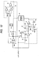
- FIG. 1 is an electric circuit diagram showing an arrangement of an applied voltage control system for the sensor element 10.
- R1 resistance value
- R2 resistance value
- an applied voltage control circuit 30 is connected to the -terminal (diffusive layer side electrode 15) of the sensor element 10.
- a point A at one end of the current detection resistor 22 is maintained at a voltage equal to a reference voltage Ref1.
- the element current Ip flows through the current detection resistor 22 and the voltage at a point B varies in accordance with the element current Ip.
- the applied voltage control circuit 30 monitors the point-B voltage (A/F output) for determining a voltage to be applied to the sensor element 10 on the basis of the monitored voltage value, and basically implements the applied voltage control so that the applied voltage increases when the element current Ip increases (that is, when the point-B voltage rises).
- the LPF 38 is composed of a resistor 38a and capacitor 38b. By passing through this LPF 38, the variation of the applied voltage output to the sensor element 10 is controlled.
- this air-fuel ratio detecting apparatus detects an alternating-current impedance Zac of the sensor element 10 through the use of the so-called sweep method and controls the element temperature at a constant value on the basis of this alternating-current impedance Zac. That is, on the basis of a command from a microcomputer (not shown), the applied voltage control circuit 30 temporarily produces an alternating-current-like variation of the sensor applied voltage to, at this time, detect the alternating-current impedance Zac on the basis of a variation of the applied voltage and a variation of the element current. Moreover, the energizing of the heater 18 is controlled to keep the alternating-current impedance Zac at a predetermined target value. This enables the sensor element 10 to be maintained at a constant target temperature (for example, 750 °C).
- a constant target temperature for example, 750 °C
- the width of the limiting current region (the absolute width of a voltage) varies in accordance with a gas atmosphere.
- the width of the limiting current region is wide in the lean region while the width of the limiting current region is narrow in the rich region.
- a detailed description will be given hereinbelow of the fact that the width of the limiting current region stands at a different value according to a gas atmosphere.
- FIG. 4A is an illustration of an equivalent circuit showing the sensor element 10 and an applied voltage Vp and, in the illustration, the sensor element 10 is shown in the form of a direct-current internal resistance Ri and an electromotive force Vk being connected in series to each other.
- FIG. 4B is an illustration of an electromotive force characteristic of the sensor element 10.
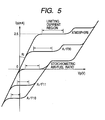
- FIG. 5 is an illustration of a sensor output characteristic (V-I characteristic) indicating the fact that the width of the limiting current region becomes a different value according to a gas atmosphere. It is considered that the width of the limiting current region is determined by the following factors: that is,
- the element current Ip increases while being bound by the direct-current internal resistance Ri.
- the exhaust gas is in a lean condition, since oxygen is not sufficiently decomposed on the diffusive layer side electrode 15 and it is not discharged, a lean condition occurs in the vicinity of the diffusive layer side electrode 15.
- the exhaust gas is in a rich condition (or stoichiometric air-fuel ratio state)
- a negative current flows when a negative voltage Vp is applied thereto, and oxygen shifts from the atmosphere side electrode to the diffusive layer side electrode.
- the components other than oxygen contained in the exhaust gas greatly affect the variation of the element current Ip.
- the deposition voltage of water (H 2 O) contained in the exhaust gas varies according to the air-fuel ratio and the degrees of decomposition easiness of the unburned components (HC, CO, H 2 , and others) differ from each other, they have influence on the variation of the element current Ip. Therefore, the voltage point at the end of the limiting current region varies according to air-fuel ratio and, consequently, the width of the limiting current region stands at a different value for each air-fuel ratio.
- the water decomposition voltage is relatively high in the atmosphere while it is relatively low in the stoichiometric state. Therefore, the width of the limiting current region becomes larger as the degree of the lean state increases.
- the width of the limiting current region becomes a different value due to a difference in reaction easiness for each gas component. That is, the oxygen quantity to be drawn from the atmosphere side electrode 16 into the diffusive layer side electrode 15 runs short with a rise of the applied voltage Vp.
- the reaction-easy gases such as CO in the exhaust gas are decomposed in the diffusive layer side electrode 15, but the reaction-hard gases such as C 3 H 8 (propane) of HC are left without being decomposed.
- the reaction-hard components are gradually decomposed so that the element current Ip increases.
- the voltage point (end point of the limiting current region) at which the element current Ip starts to increase varies accordingly and, hence, the width of the limiting current region varies.
- the applied voltage Vp further rises to cross the restriction of the gas reaction in the limiting current region
- the element current Ip approaches 0 mA
- the voltage further rises as in the case of the stoichiometric condition, water in the exhaust gas is decomposed by the electric energy in the diffusive layer side electrode 15, thus increasing the element current Ip.
- the limiting current region is established under the influence of the electromotive force of the sensor element 10 or the reaction of water of unburned components and, in consequence, the width of the limiting current region stands at a different value for each air-fuel ratio.
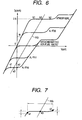
- the applied voltage characteristic is set in consideration of the width of the limiting current region. This will be described hereinbelow with reference to FIG. 6.
- the characteristic itself shown in FIG. 6 is similar to the aforesaid characteristic shown in FIG. 5.
- the width of the limiting current region stands at the smallest value at the rich limit (A/F10) forming the lower limit of the air-fuel ratio detection range, while the width of the limiting current region stands at the largest value at the lean limit (atmosphere state) forming the upper limit. Therefore, the applied voltage characteristic (applied voltage line RG) is set on the basis of the widths of the limiting current region at the rich limit and at the lean limit.
- an intermediate point a3 is obtained from the end points a1 and a2 on the low voltage side and the high voltage side in the limiting current region at the rich limit (A/F10) and an intermediate point b3 is obtained from the end points b1 and b2 on the low voltage side and the high voltage side in the limiting current region at the lean limit (atmosphere state), with the intermediate point a3 between the end points a1 and a2 and the intermediate point b3 between the end points b1 and b2 being connected to each other to linearly draw an applied voltage line RG.
- the end points (a1, a2 in FIG. 7) of the limiting current region are determined on the condition that they are wining a detection error allowed from the air-fuel ratio requirement accuracy, in other words, that the variation of the element current Ip is below a predetermined quantity, and the applied voltage line RG is set to pass through the intermediate point a3 between a1 and a2.
- the fact that the variation of the element current Ip is below the predetermined quantity also corresponds to the fact that the components other than a specific component (in this case, oxygen) do not undergo the decomposition or the like.
- the low-voltage side end point (for example, a1, b1 in FIG. 6) of the limiting current regions is a voltage point at which, when the applied voltage Vp is increased, the output of an electromotive force balanced with respect to the applied voltage Vp starts, and corresponds to a first voltage point.
- the high-voltage side end point (for example, a2, b2 in FIG. 6) is a voltage point at which the decomposition of water contained in an exhaust gas starts or a voltage point at which the element current Ip increases due to the residue of reaction-hard components of the unburned components contained in the exhaust gas, and corresponds to a second voltage point.
- the resistance values R1 to R3 are adjusted so that the inclination of the applied voltage line RG is set as mentioned above. Moreover, when the applied voltage Vp is controlled on this applied voltage line RG, the voltage is applied so as not to get out of the limiting current region irrespective of a variation of the air-fuel ratio, thereby enabling an accurate air-fuel ratio detection.
- the applied voltage line RG takes a lying state as compared with the inclination of the resistance governing region depending upon the direct-current internal resistance Ri and, hence, the feedback gain exceeds 1 in the applied voltage control circuit 30 so that the oscillation of the applied voltage Vp tends to occur.
- the LPF 38 functioning as a voltage change regulating means is provided in the applied voltage control circuit 30.
- the time constant of the LPF 38 is determined in consideration of the transitional variation of the air-fuel ratio.
- the applied voltage line RG is set on the basis of the width of the limiting current region, even if the air-fuel ratio varies in a wide air-fuel ratio detection range, the applied voltage Vp is not set out of the limiting current region. As a result, the applied voltage control can be implemented with high accuracy and, hence, the improvement of the air-fuel ratio detection accuracy is achievable over a wide range.
- the limiting current region is determined from the first voltage point (for example, a1, b1 in FIG. 6) based on the electromotive force of the sensor element 10 and the second voltage point a2, b2 in FIG. 6) based on the reaction of water or unburned components and the intermediate point therebetween is specified to set the applied voltage line RG, the element current I is detectable in a region excluding the water decomposition region or the decomposition region of the unburned components left without reacting. This enables the applied voltage Vp to be surely controlled in the limiting current region and improves the detection accuracy on the element current Ip.
- the applied voltage line RG enters a lying state as compared with the inclination of the resistance governing region depending on the direct-current internal resistance Ri, since the LPF 38 is provided in the applied voltage control circuit 30 to regulate the variation of the applied voltage Vp, the oscillation of the applied voltage Vp is preventable.
- the low-voltage side characteristic forming the connection of the low-voltage side end points (a1, b1 and others in FIG. 6) of the limiting current region and the high-voltage side characteristic forming the connection of the high-voltage side end points (a2, b2 and others in FIG. 6) of the same limiting current region are prescribed so that the applied voltage characteristic is set on the basis of an intermediate inclination between the inclinations of these characteristics.
- the applied voltage control can be implemented with high accuracy and, in consequence, the improvement of the air-fuel ratio detection accuracy is achievable over a wide range.
- the heater control is implemented so that the temperature (element temperature) of the sensor element 10 is maintained at a constant value
- the element temperature can vary thoughtlessly due to external factors. For example, it is considered that the temperature of the exhaust gas rises due to the variation of the engine operating condition to increase the element temperature or the fuel cutting is made to decrease the element temperature.
- the variation of the element temperature causes a variation of the direct-current internal resistance Ri so that a variation of the sensor output characteristic occurs and, in consequence, the limiting current region shifts along the voltage axis directions.
- the applied voltage characteristic is set in a region where limiting current regions overlap in a plurality of sensor output characteristics different in the temperature condition of the sensor element 10, and the applied voltage control is implemented.
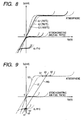
- the applied voltage line RG is set to pass through a region in which the limiting current regions overlap in a plurality of sensor output characteristics (output characteristics at a minimum temperature and output characteristics at a maximum temperature within a temperature range of use) different in element temperature condition from each other.
- FIG. 9 shows, of the characteristic lines L1 to L3, the most-lying characteristic line L2 at the element temperature of 700 °C and the most-standing characteristic line L3 at the element temperature of 1000 °C.
- the low-voltage side end points a1 and b1 (a1 denotes an end point in the case of A/F10, and b1 denotes an end point in the case of the atmosphere) in the limiting current regions are extracted from the characteristic line L2 at the element temperature of 700 °C
- the high-voltage side end points a2 and b2 (a2 denotes an end point for A/F10, and b2 denotes an end point for the atmosphere) in the limiting current regions are extracted from the characteristic line L3 at the element temperature of 1000 °C.
- the intermediate point a3 is obtained from the end points a1 and a2 in the limiting current regions for A/F10 and the intermediate point b3 is obtained from the end points b1 and b2 in the limiting current regions for the atmosphere, with the applied voltage line RG being drawn so as to make a connection between the intermediate points a3 and b3.
- the applied voltage line RG is set in this way.
- the applied voltage line RG is set to pass through limiting current regions common among all the element temperatures, the applied voltage control can be implemented so as to be always in the limiting current region irrespective of the variation of the element temperature. Moreover, since the setting of one applied voltage line RG can cope with the element temperature variation, the simplification of the circuit arrangement and others are realizable as compared with a case in which a plurality of applied voltage lines are prepared in conjunction with the element temperatures.
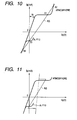
- FIG. 10 shows, in a case in which a voltage is applied at a point A1 on an applied voltage line RG in the atmosphere, if the element current Ip increases due to the disturbance such as noise, the applied voltage Vp rises temporarily. Assuming that the applied voltage Vp rises to cross a point A2, as with the point A1, the point A2 also provides a sensor output characteristic in the atmospheric condition and, hence, the state at the point A2 is fixed so that it does not return to the point A1 in the limiting current region. Accordingly, an excessive current is applied to the sensor element 10 so that there is a possibility that sensor breakdown, mistaken air-fuel ratio detection and the like occur due to damages to the solid electrolyte.
- FIG. 10 shows, in a case in which a voltage is applied at a point A1 on an applied voltage line RG in the atmosphere, if the element current Ip increases due to the disturbance such as noise, the applied voltage Vp rises temporarily. Assuming that the applied voltage Vp rises to cross a point A2, as with
- the inclination of the applied voltage line RG is increased (stood) in order to avoid the intersection with the sensor output characteristic in a region outside the air-fuel ratio detection range, i.e., on a lean side relative to the atmosphere or a rich side relative to A/F10.
- the applied voltage line RG is set as shown in FIG. 11.
- the inclination of the applied voltage line RG is changed in the air-fuel ratio detection range (A/F10 to atmosphere) and in a region existing out of this detection range and, outside the air-fuel ratio detection range, the applied voltage line is placed into a more standing state than that in the detection range.
- FIG. 12 shows a circuit arrangement for setting the applied voltage line RG shown in FIG. 11.
- an over-current monitoring circuit 40 is provided to monitor an excess current through a voltage at a point B (that is, an A/F output) in the illustration and a switch 45 and a resistor 46 are connected in parallel with a feedback resistor 33 constituting an inverting amplifier of an applied voltage control circuit 30.
- the over-current monitoring circuit 40 is composed of two comparators 41, 42 and a logical circuit (NAND circuit) 43, and a reference voltage Ref1 + Ref3 is inputted to the + terminal of the comparator 41 and the voltage at the point B is inputted to the - terminal thereof.
- a reference voltage Ref1 - Ref4 is inputted to the - terminal of the comparator 42 and the voltage at the point B is inputted to the + terminal thereof.
- the logical circuit 43 issues an H (high) output when the output of any one of the comparators 41 and 42 is in an L (low) state.
- the inclination of the applied voltage line RG is switched in a manner such that the switch 45 is turned on/off according to the output of the logical circuit 43 (output of the over-current monitoring circuit 40).
- the applied voltage line RG is set in a standing state to prevent the sensor characteristic line and the applied voltage line from intersecting with each other. That is, the applied voltage characteristic is changed at the detection of an excess current to suppress an excess voltage application stemming from noise. Moreover, an excess current is detected also at other than the noise occurrence, for example, in the case of the occurrence of temporary short-circuit (+ B short) and grounded short-circuit (GND short) in the sensor circuit, and the applied voltage characteristic is changed accordingly to suppress the excess voltage application stemming from noise. Therefore, the mistaken air-fuel ratio detection or the damage to the solid electrolyte (zirconia) are preventable.
- FIG. 13 shows a circuit arrangement for setting the applied voltage line RG shown in FIG. 13.
- an over-current monitoring circuit 40 is for monitoring an excess current through the use of a voltage (that is, A/F output) at the point B in the illustration as mentioned above with reference to FIG. 12, and a switch 51 is turned on/off in accordance with the output of the over-current monitoring circuit 40.
- the applied voltage characteristic is changed through the switching operation of the switch 51 at the detection of an excess current
- the applied voltage characteristic is thoughtlessly changed when the element current varies instantaneously due to noise, temporary short-circuit, grounding or the like, because of the rapid change from the limiting current region to the resistance governing region or the like, the applied voltage rapidly varies so that there is a possibility that the air-fuel ratio detection accuracy lowers. For this reason, the timing of the change of the applied voltage characteristic is delayed at the detection of an excess current.
- an LPF 60 is provided in an signal outputting portion of the over-current monitoring circuit 40.
- the applied voltage characteristic is not changed by an instantaneous (extremely short time) element current variation, and as a result, the air-fuel ratio detection accuracy is maintainable.
- a timer delay circuit
- the applied voltage line RG shown in FIG. 13 is also realizable by setting the resistance value R6 of the resistor 46 at 0 ⁇ in the circuit shown in FIG. 12.
- the applied voltage characteristic is defined in advance in consideration of this variation with time. That is, according to the deterioration of the sensor element 10, the direct-current internal resistance Ri increases while the inclination of the resistance governing region becomes smaller. Moreover, the frequency characteristic of the sensor element 10 varies (the frequency characteristic varies, for example, due to the fact that the capacitor portion decreases in the interior of the sensor). In this case, the initial output characteristic of the sensor element 10 and an estimated output characteristic after the variation with time are used and the applied voltage line RG is set to pass through a region in which the limiting current regions thereof overlap.
- the estimated output characteristic after the variation with time is estimated in consideration of a variation of the direct-current internal resistance Ri or frequency characteristic at the deterioration tolerance limits permitting the use of the element current output.
- proper applied voltage control is feasible even after the variation with time, and the air-fuel ration detection accuracy is maintainable over a long period of time.
- a suppressing means is appropriately set to prevent the oscillation of the applied voltage.
- the sensor frequency characteristic also varies, there is a need to consider this fact sufficiently.
- a region in which limiting current region widths are approximately equal to each other and a region in which limiting current regions are different from each other exist in the air-fuel ratio detection range.
- the widths of the limiting current regions are approximately equal to each other and in a region from the vicinity of the stoichiometric air-fuel ratio to extreme lean (atmosphere), the limiting current region width increases gradually.
- the inclination (applied voltage characteristic) of the applied voltage line RG changes partially according to air-fuel ratio region.
- the applied voltage line RG is set in parallel with the inclination (inclination of the resistance governing region) according to the direct-current internal resistance Ri of the sensor element 10 and, in a lean side, it is set in a lying state.
- the air-fuel ratio detection range is divided into a plurality of portions and the inclination of the applied voltage line RG is individually set in each of the divided detection range portions.
- the upper limit or one point in the vicinity of the upper limit on the limiting current region is specified for each detection range portion, and the lower limit or one point in the vicinity of the lower limit on the limiting current region is specified for each detection range portion, with the applied voltage line RG being set to pass through the specified points.
- the method of setting the applied voltage line RG in each detection range portion is, for example, as described above with reference to FIG. 6.
- the entire air-fuel ratio detection range from A/F10 to the atmosphere is divided into three regions, it is divided into three regions of A/F10 to stoichiometric air-fuel ratio, stoichiometric air-fuel ratio to A/F18 and A/F18 to atmosphere, and the applied voltage line only for each of the respective regions are set and they are connected to establish one applied voltage line RG.
- the region (A/F12 to A/F18) in the vicinity of the stoichiometric air-fuel ratio is divided to set the ranges, in particular, the stoichiometric combustion is securable.
- the division method can arbitrarily be determined. According to this method, the applied voltage control accuracy is further improvable.
- the applied voltage control circuit 30 is made to feedback-control the applied voltage, it is also appropriate that an applied voltage command value is outputted from a microcomputer or the like so that the applied voltage control is implemented in accordance with the command value. Also in this case, the applied voltage value may be determined in each case in consideration of the width of the limiting current region. For example, a microcomputer implements the following applied voltage control (1) and (2).
- the applied voltage line RG to be set on the V-I coordinates is one in number, an advantage is obtainable in cost.
- the present invention is not limited to this, but it is also possible to set a plurality of applied voltage lines.
- a configuration other than the LPF 38 is also usable as the voltage change regulating means. In short, it is appropriate that the gain of the applied voltage control circuit 30 is set to be below 1.
- the embodiments employ the A/F sensor having the sensor element construction shown in FIG. 2, it is also possible to employ an A/F sensor having another sensor element construction.
- the present invention is also applicable to an A/F sensor having two-layer or three-layer solid electrolyte construction, and without being limited to the A/F sensor having a multilayer construction, the present invention is also applicable to an A/F sensor having a cup-like construction.
- a sensor having an oxygen pump cell and an oxygen sensing cell there has been known a sensor having an oxygen pump cell and an oxygen sensing cell.
- an exhaust gas is introduced through a gas passage into a measured gas chamber and the oxygen pump cell outputs a current corresponding to an oxygen concentration in the measured gas chamber, thus detecting the oxygen concentration of the exhaust gas.
- the oxygen sensing cell generates an electromotive force corresponding to the oxygen concentration of the exhaust gas introduced into the measured gas chamber, and the applied voltage to the oxygen pump cell is controlled so that the electromotive force becomes constant.
- the pump cell current is controlled so as to maintain the electromotive force of the oxygen sensing cell at 0.45V.
- the electromotive force of the oxygen sensing cell may be changed according to A/F region.
- the electromotive force of the oxygen sensing cell serving as a control voltage is changed within a range of approximately 0.45V ⁇ 0.1V. This achieves the improvement of the air-fuel ratio detection accuracy.
- a compound gas concentration sensor includes a plurality of cells made from a solid electrolyte, and of these cells, a first cell (pump cell) discharges or pumps out oxygen in a detection gas and detects the oxygen concentration and a second cell (sensor cell) detects a gas concentration of a specific component in the gas after the oxygen discharge.
- This gas concentration sensor is actually used, for example, as an NOx sensor for detecting an NOx concentration in an exhaust gas, and when the present invention is applied thereto, the NOx concentration detection accuracy is improvable.
- the present invention is also applicable to a gas concentration sensor having a plurality of cells including, in addition to the aforesaid first and second cells, a third cell (monitor cell, or second pump cell) for detecting a residual oxygen concentration after the oxygen discharge.
- the applied voltage characteristic of the pump cell may be set as mentioned above to implement the applied voltage control through the use of this applied voltage characteristic.
- the present invention is also applicable to a gas concentration sensor which can detect an HC concentration or a CO concentration as a gas concentration of a specific component.
- the excess oxygen of a detection gas is discharged by a pump cell and HC or CO in the gas after the excess oxygen discharge is decomposed by a sensor cell to detect an HC concentration or a CO concentration.
- a gas other than the exhaust gas becomes a detection gas.
- the present invention relates to a gas concentration detecting apparatus capable of implementing applied voltage to a gas sensor element with high accuracy to improve the gas concentration detection accuracy over a wide range.
- the sensor element of the gas concentration detecting apparatus acting as an air-fuel ratio sensor is composed of a gas diffusion rate-determining portion, a solid electrolyte and a pair of electrodes, and an element current corresponding to a specific component concentration flows whenever a voltage is applied to the sensor element.
- An applied voltage control circuit controls the applied voltage to the sensor element on the basis of an applied voltage characteristic defined linearly.
- the applied voltage characteristic is set on the basis of a width of a limiting current region at each air-fuel ratio in a wide air-fuel ratio detection range.
Landscapes
- Chemical & Material Sciences (AREA)
- Life Sciences & Earth Sciences (AREA)
- Health & Medical Sciences (AREA)
- Physics & Mathematics (AREA)
- Chemical Kinetics & Catalysis (AREA)
- Electrochemistry (AREA)
- Molecular Biology (AREA)
- Analytical Chemistry (AREA)
- Biochemistry (AREA)
- General Health & Medical Sciences (AREA)
- General Physics & Mathematics (AREA)
- Immunology (AREA)
- Pathology (AREA)
- Measuring Oxygen Concentration In Cells (AREA)
Applications Claiming Priority (4)
| Application Number | Priority Date | Filing Date | Title |
|---|---|---|---|
| JP2003022561 | 2003-01-30 | ||
| JP2003022561 | 2003-01-30 | ||
| JP2003422905 | 2003-12-19 | ||
| JP2003422905A JP4124119B2 (ja) | 2003-01-30 | 2003-12-19 | ガス濃度検出装置 |
Publications (2)
| Publication Number | Publication Date |
|---|---|
| EP1452861A2 true EP1452861A2 (fr) | 2004-09-01 |
| EP1452861A3 EP1452861A3 (fr) | 2004-12-29 |
Family
ID=32775203
Family Applications (1)
| Application Number | Title | Priority Date | Filing Date |
|---|---|---|---|
| EP04001971A Ceased EP1452861A3 (fr) | 2003-01-30 | 2004-01-29 | Appareil pour détecter la concentration de gaz |
Country Status (3)
| Country | Link |
|---|---|
| US (1) | US20040195097A1 (fr) |
| EP (1) | EP1452861A3 (fr) |
| JP (1) | JP4124119B2 (fr) |
Cited By (4)
| Publication number | Priority date | Publication date | Assignee | Title |
|---|---|---|---|---|
| EP1860431A1 (fr) * | 2006-05-26 | 2007-11-28 | Denso Corporation | Appareil de mesure de concentration de gaz conçus pour améliorer la précision de mesure de la plage souhaitée |
| WO2008080768A1 (fr) * | 2006-12-29 | 2008-07-10 | Robert Bosch Gmbh | Élément détecteur avec courant de décalage par décomposition de h2o |
| CN101241099B (zh) * | 2007-02-05 | 2011-07-27 | 株式会社电装 | 传感器控制设备 |
| CN114251180A (zh) * | 2021-12-22 | 2022-03-29 | 重庆康明斯发动机有限公司 | 燃气发动机启动控制的方法、装置、设备以及存储介质 |
Families Citing this family (16)
| Publication number | Priority date | Publication date | Assignee | Title |
|---|---|---|---|---|
| JP4616754B2 (ja) * | 2005-11-04 | 2011-01-19 | 日本特殊陶業株式会社 | センサ制御装置 |
| JP4325684B2 (ja) | 2007-02-20 | 2009-09-02 | 株式会社デンソー | センサ制御装置、及び印加電圧特性の調整方法 |
| JP4379820B2 (ja) | 2007-02-21 | 2009-12-09 | 株式会社デンソー | センサ制御装置 |
| JP6235270B2 (ja) * | 2013-08-23 | 2017-11-22 | 株式会社Soken | 内燃機関の制御装置および制御方法 |
| JP6265094B2 (ja) | 2014-09-23 | 2018-01-24 | 株式会社デンソー | 制御装置、および、その製造方法 |
| JP2017207397A (ja) * | 2016-05-19 | 2017-11-24 | 日本特殊陶業株式会社 | ガス濃度検出装置 |
| JP2017207396A (ja) | 2016-05-19 | 2017-11-24 | 日本特殊陶業株式会社 | ガス濃度検出装置 |
| JP6494570B2 (ja) * | 2016-07-20 | 2019-04-03 | 株式会社デンソーテン | 空燃比センサの制御装置および異常検出方法 |
| DE102016220649A1 (de) * | 2016-10-20 | 2018-04-26 | Robert Bosch Gmbh | Steuereinheit zum Betrieb einer Lambdasonde |
| DE102017214205A1 (de) * | 2017-08-15 | 2019-02-21 | Robert Bosch Gmbh | Steuergerät mit Schaltung und Verfahren zum Kurzschlussschutz von Masseleitungen und Sensoren |
| JP6906454B2 (ja) * | 2018-01-31 | 2021-07-21 | 株式会社東芝 | 格納容器用酸素計測装置およびその酸素センサ |
| JP7047781B2 (ja) * | 2019-01-08 | 2022-04-05 | 株式会社デンソー | 排気システムの制御装置 |
| JP2021150046A (ja) * | 2020-03-17 | 2021-09-27 | 本田技研工業株式会社 | 水検出装置及び水検出方法 |
| JP6991410B1 (ja) * | 2021-02-26 | 2022-01-13 | 三菱電機株式会社 | 電圧管理装置、電圧指令装置、電力系統監視システム、計測装置、電圧管理方法および電圧管理プログラム |
| JP7375784B2 (ja) * | 2021-03-05 | 2023-11-08 | 横河電機株式会社 | 酸素濃度計、酸素濃度検出システム及びジルコニアセンサの抵抗検出方法 |
| WO2023181582A1 (fr) * | 2022-03-25 | 2023-09-28 | ローム株式会社 | Système capteur |
Citations (4)
| Publication number | Priority date | Publication date | Assignee | Title |
|---|---|---|---|---|
| EP0190750A1 (fr) | 1985-02-06 | 1986-08-13 | Hitachi, Ltd. | Détecteur du rapport air-carburant pour une automobile |
| EP0851108A2 (fr) | 1996-12-24 | 1998-07-01 | Denso Corporation | Système de détection de rapport air-carburant utilisant un capteur de courant limite |
| US5980710A (en) | 1997-05-21 | 1999-11-09 | Denso Corporation | Method and apparatus for gas concentration detection and manufacturing method of the apparatus |
| EP1006351A1 (fr) | 1998-12-04 | 2000-06-07 | Denso Corporation | Capteur de gaz avec de courtes connexions à un connecteur, qui contient un circuit de traitement de signaux, pour minimiser le brouillage |
Family Cites Families (4)
| Publication number | Priority date | Publication date | Assignee | Title |
|---|---|---|---|---|
| JPS61180427A (ja) * | 1985-02-06 | 1986-08-13 | Canon Inc | 集積回路基板 |
| JP3692182B2 (ja) * | 1996-06-28 | 2005-09-07 | 日本碍子株式会社 | ガスセンサ、ガスセンサの制御方法及びガス濃度制御器 |
| JP3680445B2 (ja) * | 1996-10-08 | 2005-08-10 | 株式会社デンソー | 酸素濃度検出装置 |
| JP3846058B2 (ja) * | 1998-09-04 | 2006-11-15 | 株式会社デンソー | ガス濃度検出装置 |
-
2003
- 2003-12-19 JP JP2003422905A patent/JP4124119B2/ja not_active Expired - Lifetime
-
2004
- 2004-01-29 EP EP04001971A patent/EP1452861A3/fr not_active Ceased
- 2004-01-29 US US10/765,881 patent/US20040195097A1/en not_active Abandoned
Patent Citations (4)
| Publication number | Priority date | Publication date | Assignee | Title |
|---|---|---|---|---|
| EP0190750A1 (fr) | 1985-02-06 | 1986-08-13 | Hitachi, Ltd. | Détecteur du rapport air-carburant pour une automobile |
| EP0851108A2 (fr) | 1996-12-24 | 1998-07-01 | Denso Corporation | Système de détection de rapport air-carburant utilisant un capteur de courant limite |
| US5980710A (en) | 1997-05-21 | 1999-11-09 | Denso Corporation | Method and apparatus for gas concentration detection and manufacturing method of the apparatus |
| EP1006351A1 (fr) | 1998-12-04 | 2000-06-07 | Denso Corporation | Capteur de gaz avec de courtes connexions à un connecteur, qui contient un circuit de traitement de signaux, pour minimiser le brouillage |
Cited By (6)
| Publication number | Priority date | Publication date | Assignee | Title |
|---|---|---|---|---|
| EP1860431A1 (fr) * | 2006-05-26 | 2007-11-28 | Denso Corporation | Appareil de mesure de concentration de gaz conçus pour améliorer la précision de mesure de la plage souhaitée |
| US7981265B2 (en) | 2006-05-26 | 2011-07-19 | Denso Corporation | Gas concentration measuring apparatus designed to enhance measurement accuracy in desired range |
| WO2008080768A1 (fr) * | 2006-12-29 | 2008-07-10 | Robert Bosch Gmbh | Élément détecteur avec courant de décalage par décomposition de h2o |
| CN101241099B (zh) * | 2007-02-05 | 2011-07-27 | 株式会社电装 | 传感器控制设备 |
| CN114251180A (zh) * | 2021-12-22 | 2022-03-29 | 重庆康明斯发动机有限公司 | 燃气发动机启动控制的方法、装置、设备以及存储介质 |
| CN114251180B (zh) * | 2021-12-22 | 2024-05-28 | 重庆康明斯发动机有限公司 | 燃气发动机启动控制的方法、装置、设备以及存储介质 |
Also Published As
| Publication number | Publication date |
|---|---|
| US20040195097A1 (en) | 2004-10-07 |
| JP2004251891A (ja) | 2004-09-09 |
| EP1452861A3 (fr) | 2004-12-29 |
| JP4124119B2 (ja) | 2008-07-23 |
Similar Documents
| Publication | Publication Date | Title |
|---|---|---|
| EP1452861A2 (fr) | Appareil pour détecter la concentration de gaz | |
| US6870142B2 (en) | Power supply control system for heater used in gas sensor | |
| EP1026501B1 (fr) | Dispositif de mesure de la concentration d'un gaz avec compensation d'erreurs du signal de sortie | |
| JP5099070B2 (ja) | センサ制御装置及びセンサユニット | |
| JP4093190B2 (ja) | ガス濃度検出装置 | |
| US7481913B2 (en) | High-resolution gas concentration measuring apparatus | |
| US7955494B2 (en) | Gas sensor control apparatus | |
| JP3846058B2 (ja) | ガス濃度検出装置 | |
| US7938944B2 (en) | Gas concentration measurement apparatus | |
| JP4872198B2 (ja) | ガス濃度検出装置 | |
| JP4697052B2 (ja) | ガス濃度検出装置 | |
| JP3487161B2 (ja) | ガス濃度センサ用制御装置 | |
| JP2002116180A (ja) | ガス濃度検出装置とそれに用いるガス濃度センサ | |
| JP4325054B2 (ja) | ガス濃度検出装置 | |
| JP2008076410A (ja) | ガス濃度検出装置 | |
| JP2001133429A (ja) | 車載用noxセンサのオフセット再校正方法 | |
| JP4111169B2 (ja) | ガス濃度検出装置 | |
| JP5067469B2 (ja) | ガス濃度検出装置 | |
| JP4016964B2 (ja) | ガス濃度検出装置 | |
| US20070007134A1 (en) | Gas concentration measuring apparatus designed to establish quick determination of degree of activation of gas sensor | |
| JP4569701B2 (ja) | ガス濃度検出装置 | |
| CN103314287B (zh) | 用于检测气体的至少一个参数的方法和装置 | |
| JP2007248113A (ja) | ガス濃度検出装置 | |
| JP3867610B2 (ja) | ガスセンサ素子 | |
| JP2000356620A (ja) | ガス濃度検出装置 |
Legal Events
| Date | Code | Title | Description |
|---|---|---|---|
| PUAI | Public reference made under article 153(3) epc to a published international application that has entered the european phase |
Free format text: ORIGINAL CODE: 0009012 |
|
| AK | Designated contracting states |
Kind code of ref document: A2 Designated state(s): AT BE BG CH CY CZ DE DK EE ES FI FR GB GR HU IE IT LI LU MC NL PT RO SE SI SK TR |
|
| AX | Request for extension of the european patent |
Extension state: AL LT LV MK |
|
| PUAL | Search report despatched |
Free format text: ORIGINAL CODE: 0009013 |
|
| AK | Designated contracting states |
Kind code of ref document: A3 Designated state(s): AT BE BG CH CY CZ DE DK EE ES FI FR GB GR HU IE IT LI LU MC NL PT RO SE SI SK TR |
|
| AX | Request for extension of the european patent |
Extension state: AL LT LV MK |
|
| 17P | Request for examination filed |
Effective date: 20050128 |
|
| AKX | Designation fees paid |
Designated state(s): DE FR GB |
|
| 17Q | First examination report despatched |
Effective date: 20090220 |
|
| STAA | Information on the status of an ep patent application or granted ep patent |
Free format text: STATUS: THE APPLICATION HAS BEEN REFUSED |
|
| 18R | Application refused |
Effective date: 20121008 |