EP1453014B1 - Vorrichtung für die Abtastung von Bankschecks mit einer verbesserten Scheckzufuhrvorrichtung - Google Patents
Vorrichtung für die Abtastung von Bankschecks mit einer verbesserten Scheckzufuhrvorrichtung Download PDFInfo
- Publication number
- EP1453014B1 EP1453014B1 EP04004423A EP04004423A EP1453014B1 EP 1453014 B1 EP1453014 B1 EP 1453014B1 EP 04004423 A EP04004423 A EP 04004423A EP 04004423 A EP04004423 A EP 04004423A EP 1453014 B1 EP1453014 B1 EP 1453014B1
- Authority
- EP
- European Patent Office
- Prior art keywords
- plate
- feed
- cheque
- cheques
- input receptacle
- Prior art date
- Legal status (The legal status is an assumption and is not a legal conclusion. Google has not performed a legal analysis and makes no representation as to the accuracy of the status listed.)
- Expired - Lifetime
Links
- 230000007246 mechanism Effects 0.000 claims abstract description 9
- 238000003780 insertion Methods 0.000 claims abstract description 3
- 230000037431 insertion Effects 0.000 claims abstract description 3
- 230000005540 biological transmission Effects 0.000 claims description 10
- 230000004913 activation Effects 0.000 description 2
- 230000009849 deactivation Effects 0.000 description 2
- 230000003287 optical effect Effects 0.000 description 2
- 239000007787 solid Substances 0.000 description 2
- 230000009471 action Effects 0.000 description 1
- 238000000034 method Methods 0.000 description 1
Images



Classifications
-
- B—PERFORMING OPERATIONS; TRANSPORTING
- B65—CONVEYING; PACKING; STORING; HANDLING THIN OR FILAMENTARY MATERIAL
- B65H—HANDLING THIN OR FILAMENTARY MATERIAL, e.g. SHEETS, WEBS, CABLES
- B65H1/00—Supports or magazines for piles from which articles are to be separated
- B65H1/08—Supports or magazines for piles from which articles are to be separated with means for advancing the articles to present the articles to the separating device
- B65H1/12—Supports or magazines for piles from which articles are to be separated with means for advancing the articles to present the articles to the separating device comprising spring
-
- G—PHYSICS
- G07—CHECKING-DEVICES
- G07D—HANDLING OF COINS OR VALUABLE PAPERS, e.g. TESTING, SORTING BY DENOMINATIONS, COUNTING, DISPENSING, CHANGING OR DEPOSITING
- G07D11/00—Devices accepting coins; Devices accepting, dispensing, sorting or counting valuable papers
- G07D11/10—Mechanical details
- G07D11/14—Inlet or outlet ports
-
- B—PERFORMING OPERATIONS; TRANSPORTING
- B65—CONVEYING; PACKING; STORING; HANDLING THIN OR FILAMENTARY MATERIAL
- B65H—HANDLING THIN OR FILAMENTARY MATERIAL, e.g. SHEETS, WEBS, CABLES
- B65H2301/00—Handling processes for sheets or webs
- B65H2301/30—Orientation, displacement, position of the handled material
- B65H2301/31—Features of transport path
- B65H2301/312—Features of transport path for transport path involving at least two planes of transport forming an angle between each other
- B65H2301/3122—U-shaped
-
- B—PERFORMING OPERATIONS; TRANSPORTING
- B65—CONVEYING; PACKING; STORING; HANDLING THIN OR FILAMENTARY MATERIAL
- B65H—HANDLING THIN OR FILAMENTARY MATERIAL, e.g. SHEETS, WEBS, CABLES
- B65H2301/00—Handling processes for sheets or webs
- B65H2301/30—Orientation, displacement, position of the handled material
- B65H2301/32—Orientation of handled material
- B65H2301/321—Standing on edge
-
- B—PERFORMING OPERATIONS; TRANSPORTING
- B65—CONVEYING; PACKING; STORING; HANDLING THIN OR FILAMENTARY MATERIAL
- B65H—HANDLING THIN OR FILAMENTARY MATERIAL, e.g. SHEETS, WEBS, CABLES
- B65H2403/00—Power transmission; Driving means
- B65H2403/50—Driving mechanisms
- B65H2403/53—Articulated mechanisms
- B65H2403/531—Planar mechanisms
- B65H2403/5311—Parallelogram mechanisms
-
- B—PERFORMING OPERATIONS; TRANSPORTING
- B65—CONVEYING; PACKING; STORING; HANDLING THIN OR FILAMENTARY MATERIAL
- B65H—HANDLING THIN OR FILAMENTARY MATERIAL, e.g. SHEETS, WEBS, CABLES
- B65H2701/00—Handled material; Storage means
- B65H2701/10—Handled articles or webs
- B65H2701/19—Specific article or web
- B65H2701/1912—Banknotes, bills and cheques or the like
-
- B—PERFORMING OPERATIONS; TRANSPORTING
- B65—CONVEYING; PACKING; STORING; HANDLING THIN OR FILAMENTARY MATERIAL
- B65H—HANDLING THIN OR FILAMENTARY MATERIAL, e.g. SHEETS, WEBS, CABLES
- B65H2801/00—Application field
- B65H2801/39—Scanning
Definitions
- the present invention relates to a scanner apparatus for scanning bank cheques, with an improved cheque feed device.
- apparatus for scanning cheques comprises a conveyor mechanism for conveying the cheques, one at a time, from an input receptacle to an output receptacle, passing in front of an image-scanner unit for scanning one or both faces of the cheque.
- a user uses two different types of scanning apparatus for scanning bank cheques, a first type for scanning individual cheques which are introduced into the input receptacle one at a time, and a second type for scanning bundles of cheques.
- a bundle of cheques is introduced into an input receptacle between a feed plate and a motor-driven feed roller against which the feed plate is urged resiliently and which picks up one cheque at a time from the input receptacle and conveys it towards the interior of the apparatus.
- it is necessary to move the plate manually away from the pick-up roller, acting against the force of a resilient element which urges the plate against the roller.
- US-A-4 299 073 discloses an apparatus having the features defined in the preamble of claim 1.
- the object of the present invention is to provide a scanning apparatus which has a feed device that can control the feeding-in both of cheques that are introduced into the input receptacle individually or in small groups, and of bundles of stacked cheques.
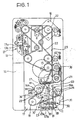
- an apparatus for scanning cheques comprises a body 10 which forms an input receptacle 11 in which one or more cheques or a bundle of cheques to be scanned can be arranged vertically (by the procedures described below). Inside the body 10 there is a conveyor mechanism of per se known type for conveying the cheques, one at a time, from the input receptacle 11 to an output receptacle 12, following a substantially U-shaped path and passing in front of an image-scanner device 13 for scanning one or both faces of the cheque.
- the cheques are picked up from the input receptacle 11 by a feed device described in detail below and comprising a feed roller 14 which cooperates with a feed plate 15.
- a photocell 16a, 16b detects the presence of a cheque in the input receptacle and activates two stepping electric motors 17, 18 which set two respective transmission belts 21, 22 in circulation by means of motor-driven rollers 19, 20; the belts 21, 22 cause one cheque at a time to move forwards, following a path which extends between a pair of image-scanner units 13a, 13b each provided with a respective CIS (compact image sensor) optical sensor in order to scan both faces (front and rear) of the cheque.
- An electronic control unit (not shown) supervises the operation of the apparatus as a whole and hence also the coordinated operation of all of the above-mentioned drive/actuator members and optical/electronic devices.
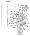
- the feed device is shown in greater detail in Figure 2 .
- the feed plate 15 is mounted on a parallelogram-type translation mechanism 23 housed in the lower portion of the casing.
- the translation mechanism 23 comprises a pair of parallel levers 24a, 24b which are articulated to the casing at first ends 25a, 25b and are articulated to one another at their opposite ends by a connecting bar (not shown).
- the lever 24a carries a pin 26 which is engaged for sliding in an arcuate slot 27 formed in the casing 10 or in an element fixed thereto.
- a biasing spring 28 urges the mechanism 23 with the feed plate 15 towards an opposed guide surface 29 disposed on the same side as the pick-up and feed roller 14, and thus brings about translation of the plate towards that roller.
- the transmission belt 21 circulates around the motor-driven roller 19, a transmission roller 30 disposed further downstream (in the direction of movement of the cheques, indicated by the arrow B in Figure 2 ), and around the feed roller 14.
- the roller 14 is mounted on a lever 31 which is articulated to the body of the apparatus at 32 and is acted on by a biasing spring 33 which tends to bring the lever to the rest position shown in solid outline in Figure 1 , in which the roller 14 is moved away from the feed plate 15 and from the input receptacle 11.
- a belt-tensioner device 34 associated with the belt 21 has an idle roller 35 mounted on a pivotable lever 36 which is acted on by a spring 37.
- An important characteristic of the solution according to the present invention is that the feed plate 15 is prevented from coming into abutment with the fixed guide surface 29 so that, when the plate reaches its position closest to the surface 29, there is still a sufficient gap 40 between this surface and the plate 15 for the insertion of at least one cheque in the input receptacle, as shown in Figure 3 .
- the travel of the plate 15 towards the guide surface 29 is in fact limited by the length of the arcuate slot 27 which has a stop surface 27a (constituted in this embodiment by an end of the slot itself) for the pin 26 which is secured to the plate 15.
- the feed device according to the invention operates as follows.
- the bundle is inserted in the input receptacle 11 by moving the feed plate 15 manually away from the guide surface 29, against the action of the spring 28.
- the plate 15 When the plate 15 is released, it urges the cheques against the opposed guide surface 29.
- the photocell 16a, 16b which is obscured by the cheques A, activates the first motor 17, by means of an electronic control unit ECU (not shown), in order to pick up a cheque and the second motor 18 in order to move the cheque through the apparatus.
- ECU electronice control unit
- the first motor 17 sets the motor-driven wheel 19 in rotation, which causes the transmission belt 21 to circulate in the direction indicated by the arrow C in Figure 2 .
- the transmission belt 21 acts on the roller 14, pulling it into contact with the cheque disposed adjacent the guide surface 29, causing the lever 31 to pivot in the anticlockwise direction indicated by the double arrow D in Figure 2 .
- the feed roller 14 moves from the position shown in solid outline in Figure 1 to the position 14' shown in broken outline and, as it rotates, picks up one or more cheques from the input receptacle and transfers them towards a pair of motor-driven separator rollers 38, 39. Since the separator roller 39 is contrarotatory relative to the roller 38, it separates the cheques, allowing only the cheque that is disposed farthest to the right (with reference to Figure 2 ) to move forwards and pushing the others backwards. The cheque is then transferred along a predetermined path inside the apparatus, is scanned and, finally, is deposited in an output receptacle 27 by the second feed belt 22, in known manner.
- the cheques of the bundle that is deposited in the input receptacle are automatically transferred and scanned one at a time sequentially.
- the plate 15 is moved progressively towards the right in order to keep the cheques in contact with the wheel 14.
- the motor 17 is stopped and the biasing spring 33 causes the lever 31 to pivot clockwise, moving the roller 14 away from the receptacle 11.
- the movements of the belt tensioner 34 follow the pivoting movements of the lever 31; naturally, the spring 37 of the belt tensioner 34 is calibrated to compensate for the slackening of the belt caused by the anticlockwise pivoting of the lever 31 but should not appreciably impede its movements.
- the feed plate 15 when the feed plate 15 is in its position closest to the surface 29, it is possible to insert a cheque in the gap 40 without the need to move the plate 15 manually.
- the scanner apparatus can therefore conveniently be used for the scanning both of individual cheques and of bundles of cheques.
- an operating sequence wholly similar to that described above is also performed when a single cheque A is deposited in the input receptacle in the gap 40 defined between the guide surface 29 and the plate 15 which is in the position in which it is extended farthest towards the surface 29. It will be noted that the width of the gap 40 actually allows even more than one cheque to be introduced without the need to move the plate 15 manually, according to the arrangement of the slot 27 relative to the surface 29.
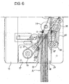
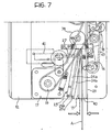
- the variant shown in Figures 4 to 8 differs from that described above with reference to Figures 1 to 3 in that the transmission belt 21 does not engage the feed roller 14 and that the position of this feed roller is controlled by an electromagnetic actuator 41.
- the belt 21 transmits the rotary movement of the motor-driven roller 19 to a transmission wheel 42. This wheel rotates the feed roller 14 by means of a further transmission belt 43.
- the activation and deactivation of the motor 17 is accompanied by simultaneous activation and deactivation of the electromagnetic actuator 41 which moves the roller 14 towards and away from the cheque-input receptacle by means of an extensible rod 44 acting on the lever 31 with the interposition of a spring 45.
Landscapes
- General Physics & Mathematics (AREA)
- Engineering & Computer Science (AREA)
- Mechanical Engineering (AREA)
- Physics & Mathematics (AREA)
- Image Input (AREA)
- Conveying Record Carriers (AREA)
- Facsimile Scanning Arrangements (AREA)
- Sheets, Magazines, And Separation Thereof (AREA)
- Automatic Analysis And Handling Materials Therefor (AREA)
- Organic Low-Molecular-Weight Compounds And Preparation Thereof (AREA)
- Cephalosporin Compounds (AREA)
- Measurement Of Radiation (AREA)
- Intermediate Stations On Conveyors (AREA)
- Character Input (AREA)
- Inspection Of Paper Currency And Valuable Securities (AREA)
Claims (8)
- Scanner-Vorrichtung zum Scannen von Bankschecks, wobei die Scanner-Vorrichtung umfasst:ein Gehäuse (10),ein Eingabefach (11), um zumindest einen Scheck aufzunehmen, der gescannt werden soll,eine Bildscanner-Einrichtung (13), um zumindest eine der Flächen des Schecks zu scannen,ein Ausgabefach (12), um den Scheck aufzunehmen, nachdem er von der Scanner-Einrichtung gescannt wurde,eine Transporteinrichtung (17-22), um die Schecks vom Eingabefach (11) zum Ausgabefach (12) einzeln entlang einer Bahn zu transportieren, die vor der Scanner-Einrichtung verläuft,eine Zuführeinrichtung, um die Schecks vom Eingebfach (11) aufzunehmen und sie zur Transporteinrichtung zu transportieren, wobei die Zuführeinrichtung aufweist:- eine Zuführplatte (15), die im Eingabefach (11) bewegbar und einer Andrückeinrichtung zugeordnet ist, um die Platte elastisch gegen eine gegenüberliegende, ortsfeste Fläche (29) zu drücken, wobei die Platte (15) eine Stelle erreichen kann, die von der Fläche (29) entfernt liegt, um zwischen der Platte und der Fläche (29) ein Bündel von Schecks aufzunehmen, und- ein Zuführrolle (14), die auf jene Seite wirkt, die von der Platte entfernt liegt, um vom Eingabefach (11) einen Scheck aufzunehmen, der neben der Fläche (29) angeordnet ist, und den Scheck zum Inneren der Vorrichtung zu transportieren,dadurch gekennzeichnet, dass der Zuführplatte (15) eine Anschlageinrichtung (27a) zugeordnet ist, um zu verhindern, dass die Platte (15) auf der Fläche (29) aufliegen kann, und die Bewegung der Platte zur gegenüberliegenden Fläche (29) in eine Stellung nahe zu dieser Fläche anzuhalten, um zwischen der Platte (15) und der Fläche (29) einen Spalt (40) auszubilden, der eine ausreichend große Breite besitzt, um zumindest einen Scheck in das Eingabefach (11) einführen zu können, wobei die Anschlageinrichtung (27a) von dem Gehäuse (10) oder von einem am Gehäuse befestigten Element gebildet wird.
- Scanner-Vorrichtung gemäß Anspruch 1, dadurch gekennzeichnet, dass die Anschlageinrichtung (27a) von einem Schlitz (27) gebildet wird, in den ein Zapfen (26) eingreift, der so angebracht ist, dass er mit der Zuführplatte (15) bewegbar ist.
- Scanner-Vorrichtung gemäß Anspruch 2, dadurch gekennzeichnet, dass die Anschlageinrichtung (27a) von einem Ende des Schlitzes (27) gebildet wird.
- Scanner-Vorrichtung gemäß Anspruch 1, dadurch gekennzeichnet, dass die Zuführrolle (14) auf einem Halterungselement (31) befestigt ist, das am Chassis der Vorrichtung bewegbar angebracht und einer Einrichtung (21, 41) zugeordnet ist, um die Zuführrolle (14) und das Halterungselement (31) zu bewegen und zwar zwischen:einer Ruhestellung, die von der Zuführplatte (15) entfernt ist, undeiner aktiven Stellung in der Nähe der Zuführplatte (15), in der die Zuführrolle (14) mit einem Scheck im Eingabefach (11) in Eingriff tritt.
- Scanner-Vorrichtung gemäß Anspruch 4, dadurch gekennzeichnet, dass das Halterungselement (31) aus einem Hebel besteht, der im Chassis der Vorrichtung gelenkig gelagert (32) ist.
- Scanner-Vorrichtung gemäß Anspruch 4, dadurch gekennzeichnet, dass:die Zuführrolle (14) auf einem Halterungselement (31) befestigt ist, das am Chassis der Vorrichtung bewegbar (32) angebracht ist, wobei ihm eine Vorspannungsfeder (33) zugeordnet ist, die dazu vorgesehen ist, um die Rolle (14) und das Halterungselement (31) in eine Ruhestellung zu bringen, die von der Zuführplatte (15) entfernt ist, und dass:die Zuführrolle (14) mit einem Transmissionsriemen (21) in Eingriff steht, der von einer Antriebsrolle (19) angetrieben wird,wodurch die Drehung der Antriebsrolle (19) mit Hilfe des Riemens (21) eine Drehung der Antriebsrolle (14) sowie eine Bewegung des Halterungselements (31) zur Zuführplatte (15) in eine aktive Stellung hervorruft, in der die Zuführrolle (14) mit einem Scheck im Aufnahmefach (11) in Eingriff tritt.
- Scanner-Vorrichtung gemäß Anspruch 6, dadurch gekennzeichnet, dass dem Transmissionsriemen (21) eine Spannvorrichtung (34) zugeordnet ist, um ein Durchhängen des Riemens zu kompensieren, das von der Bewegung des Halterungselements (31) in die aktive Stellung stammt.
- Scanner-Vorrichtung gemäß Anspruch 4, dadurch gekennzeichnet, dass die Einrichtung zum Bewegen der Zuführrolle (14) und des Halterungselements (31) ein elektromagnetisches Stellglied (41) umfasst.
Applications Claiming Priority (2)
| Application Number | Priority Date | Filing Date | Title |
|---|---|---|---|
| ITTO20030033 | 2003-02-27 | ||
| IT000033U ITTO20030033U1 (it) | 2003-02-27 | 2003-02-27 | Apparecchio per la scannerizzazione di assegni bancari con un dispositivo di tipo perfezionato per l'alimentazione di assegni. |
Publications (3)
| Publication Number | Publication Date |
|---|---|
| EP1453014A2 EP1453014A2 (de) | 2004-09-01 |
| EP1453014A3 EP1453014A3 (de) | 2005-01-05 |
| EP1453014B1 true EP1453014B1 (de) | 2011-04-20 |
Family
ID=33495876
Family Applications (1)
| Application Number | Title | Priority Date | Filing Date |
|---|---|---|---|
| EP04004423A Expired - Lifetime EP1453014B1 (de) | 2003-02-27 | 2004-02-26 | Vorrichtung für die Abtastung von Bankschecks mit einer verbesserten Scheckzufuhrvorrichtung |
Country Status (7)
| Country | Link |
|---|---|
| US (1) | US6966554B2 (de) |
| EP (1) | EP1453014B1 (de) |
| AT (1) | ATE506666T1 (de) |
| DE (1) | DE602004032284D1 (de) |
| ES (1) | ES2365332T3 (de) |
| IT (1) | ITTO20030033U1 (de) |
| PT (1) | PT1453014E (de) |
Families Citing this family (13)
| Publication number | Priority date | Publication date | Assignee | Title |
|---|---|---|---|---|
| US7407158B2 (en) * | 2004-05-14 | 2008-08-05 | Seiko Epson Corporation | Sheet feeding device with variable faced roller and integrated sheet guides |
| US7651083B2 (en) | 2006-09-21 | 2010-01-26 | Digital Check Corporation | Conveying apparatus and method |
| US20080099980A1 (en) | 2006-10-26 | 2008-05-01 | Seiko Epson Corporation | Sheet media feeding device, sheet media separation method, and sheet media processing device |
| US8018632B2 (en) | 2006-11-09 | 2011-09-13 | Pertech Resources, Inc. | Scanner/imager |
| JP4876956B2 (ja) * | 2007-02-19 | 2012-02-15 | セイコーエプソン株式会社 | 媒体処理装置 |
| EP1964801B1 (de) | 2007-03-01 | 2014-02-26 | Seiko Epson Corporation | Medienspeichervorrichtung und Medienverarbeitungsvorrichtung |
| ITTO20080854A1 (it) * | 2008-11-19 | 2010-05-20 | Panini Spa | Apparecchio scanner per la scansione di documenti cartacei, in particolare assegni bancari |
| US8262076B2 (en) | 2010-07-08 | 2012-09-11 | Ncr Corporation | Media depository |
| ITTO20110965A1 (it) | 2011-10-25 | 2013-04-26 | Panini Spa | Dispositivo alimentatore di ingresso per un apparecchio per il trattamento di documenti cartacei, in particolare assegni bancari |
| US9472041B2 (en) * | 2013-10-31 | 2016-10-18 | Ncr Corporation | Clamping of media items |
| KR101627424B1 (ko) * | 2014-10-16 | 2016-06-03 | 주식회사 엘지씨엔에스 | 매체 보관함 및 금융기기 |
| WO2018048434A1 (en) | 2016-09-12 | 2018-03-15 | Hewlett-Packard Development Company, L.P. | Belt tensioning system |
| EP3229213B1 (de) * | 2016-09-20 | 2018-09-12 | Wincor Nixdorf International GmbH | Vorrichtung zur ausgabe von wertnoten mit einem anpassbaren führungselement |
Family Cites Families (12)
| Publication number | Priority date | Publication date | Assignee | Title |
|---|---|---|---|---|
| GB1424885A (en) * | 1973-06-19 | 1976-02-11 | Bell Punch Co Ltd | Printing machines |
| US4299073A (en) * | 1979-11-09 | 1981-11-10 | American Express Company | Machine and method for packaging travelers checks |
| JPS5749961A (en) * | 1980-09-10 | 1982-03-24 | Sharp Corp | Paper feeder of copying machine |
| JPS63230435A (ja) * | 1987-03-20 | 1988-09-26 | Fuji Photo Film Co Ltd | シ−ト供給装置 |
| JPH0194327U (de) * | 1987-12-11 | 1989-06-21 | ||
| JP2513869B2 (ja) * | 1989-12-11 | 1996-07-03 | キヤノン株式会社 | 給紙装置 |
| US5165677A (en) * | 1990-01-12 | 1992-11-24 | Ricoh Company, Ltd. | Intermediate paper feeding device for a copier operable in a two-side copy mode |
| US5327206A (en) * | 1991-07-17 | 1994-07-05 | Minolta Camera Kabushiki Kaisha | Image forming apparatus including a sheet refeeding unit |
| US5867196A (en) * | 1994-07-29 | 1999-02-02 | Canon Kabushiki Kaisha | Sheet supply apparatus for controlling sheet feeding with reversing of conveyance direction |
| US6244583B1 (en) * | 1997-03-11 | 2001-06-12 | Minolta Co., Ltd. | Stack transport for a sorter with pressing device |
| US6493534B2 (en) * | 2000-02-01 | 2002-12-10 | Canon Kabushiki Kaisha | Sheet conveying apparatus and image forming apparatus |
| JP3863381B2 (ja) * | 2000-04-28 | 2006-12-27 | 京セラミタ株式会社 | 原稿搬送装置及び画像形成機 |
-
2003
- 2003-02-27 IT IT000033U patent/ITTO20030033U1/it unknown
-
2004
- 2004-02-26 PT PT04004423T patent/PT1453014E/pt unknown
- 2004-02-26 DE DE602004032284T patent/DE602004032284D1/de not_active Expired - Lifetime
- 2004-02-26 ES ES04004423T patent/ES2365332T3/es not_active Expired - Lifetime
- 2004-02-26 EP EP04004423A patent/EP1453014B1/de not_active Expired - Lifetime
- 2004-02-26 AT AT04004423T patent/ATE506666T1/de not_active IP Right Cessation
- 2004-02-26 US US10/788,250 patent/US6966554B2/en not_active Expired - Lifetime
Also Published As
| Publication number | Publication date |
|---|---|
| ATE506666T1 (de) | 2011-05-15 |
| US6966554B2 (en) | 2005-11-22 |
| EP1453014A2 (de) | 2004-09-01 |
| PT1453014E (pt) | 2011-05-02 |
| US20040251588A1 (en) | 2004-12-16 |
| ES2365332T3 (es) | 2011-09-29 |
| EP1453014A3 (de) | 2005-01-05 |
| ITTO20030033U1 (it) | 2004-08-28 |
| DE602004032284D1 (de) | 2011-06-01 |
Similar Documents
| Publication | Publication Date | Title |
|---|---|---|
| EP1453014B1 (de) | Vorrichtung für die Abtastung von Bankschecks mit einer verbesserten Scheckzufuhrvorrichtung | |
| EP0762719B1 (de) | Dokumentbeförderungsvorrichtung in einem Datenverarbeitungsgerät | |
| RU2067540C1 (ru) | Способ подачи печатных изделий к узлу для дальнейшей обработки и устройство для его осуществления | |
| US7530568B2 (en) | Double-sided document transport device | |
| US20070284803A1 (en) | Sheet feeding device, and document feeding device in image reading apparatus comprising the same | |
| JP2694706B2 (ja) | 枚葉状記録媒体を収納するための仕分け装置 | |
| EP0881184B1 (de) | Vorrichtung zum Einfügen von flachen Produkten | |
| US20040071486A1 (en) | Image reading apparatus and image forming apparatus provided with the same | |
| EP0622011B1 (de) | Ballen-Sammler mit Rollen und Ballenpresse dafür | |
| EP0468589A1 (de) | Greifer für Gegenstände wie Eier und Fördervorrichtung mit einem solchen Greifer | |
| EP0066049A2 (de) | Hin- und herbeweglicher Wagen zur Zuführung von Dokumenten | |
| US7467450B2 (en) | Book block transport system | |
| KR20060132480A (ko) | 지폐 처리기 | |
| US7651083B2 (en) | Conveying apparatus and method | |
| US4633644A (en) | Device for inserting bundles into envelopes | |
| JPH06156844A (ja) | 紙幣収納装置 | |
| JPH0235713Y2 (de) | ||
| JP3771059B2 (ja) | カード供給装置 | |
| EP1144204B1 (de) | Verbindungsmodul zwischen drucker und kuvertiermaschine | |
| JP2831458B2 (ja) | 給紙装置 | |
| EP1270267B1 (de) | Postbearbeitungsmaschine | |
| US7201524B2 (en) | Media path direction control device and method of reversing a media path | |
| US5890710A (en) | Document feeder apparatus | |
| JP4048899B2 (ja) | プリンタの用紙ガイド機構及びこれを備えたプリンタ | |
| GB2064489A (en) | Form guiding device |
Legal Events
| Date | Code | Title | Description |
|---|---|---|---|
| PUAI | Public reference made under article 153(3) epc to a published international application that has entered the european phase |
Free format text: ORIGINAL CODE: 0009012 |
|
| AK | Designated contracting states |
Kind code of ref document: A2 Designated state(s): AT BE BG CH CY CZ DE DK EE ES FI FR GB GR HU IE IT LI LU MC NL PT RO SE SI SK TR |
|
| AX | Request for extension of the european patent |
Extension state: AL LT LV MK |
|
| PUAL | Search report despatched |
Free format text: ORIGINAL CODE: 0009013 |
|
| AK | Designated contracting states |
Kind code of ref document: A3 Designated state(s): AT BE BG CH CY CZ DE DK EE ES FI FR GB GR HU IE IT LI LU MC NL PT RO SE SI SK TR |
|
| AX | Request for extension of the european patent |
Extension state: AL LT LV MK |
|
| 17P | Request for examination filed |
Effective date: 20050701 |
|
| AKX | Designation fees paid |
Designated state(s): AT BE BG CH CY CZ DE DK EE ES FI FR GB GR HU IE IT LI LU MC NL PT RO SE SI SK TR |
|
| 17Q | First examination report despatched |
Effective date: 20060818 |
|
| GRAP | Despatch of communication of intention to grant a patent |
Free format text: ORIGINAL CODE: EPIDOSNIGR1 |
|
| GRAS | Grant fee paid |
Free format text: ORIGINAL CODE: EPIDOSNIGR3 |
|
| GRAA | (expected) grant |
Free format text: ORIGINAL CODE: 0009210 |
|
| AK | Designated contracting states |
Kind code of ref document: B1 Designated state(s): AT BE BG CH CY CZ DE DK EE ES FI FR GB GR HU IE IT LI LU MC NL PT RO SE SI SK TR |
|
| REG | Reference to a national code |
Ref country code: GB Ref legal event code: FG4D |
|
| REG | Reference to a national code |
Ref country code: CH Ref legal event code: EP |
|
| REG | Reference to a national code |
Ref country code: PT Ref legal event code: SC4A Free format text: AVAILABILITY OF NATIONAL TRANSLATION Effective date: 20110420 |
|
| REG | Reference to a national code |
Ref country code: IE Ref legal event code: FG4D |
|
| REF | Corresponds to: |
Ref document number: 602004032284 Country of ref document: DE Date of ref document: 20110601 Kind code of ref document: P |
|
| REG | Reference to a national code |
Ref country code: DE Ref legal event code: R096 Ref document number: 602004032284 Country of ref document: DE Effective date: 20110601 |
|
| REG | Reference to a national code |
Ref country code: NL Ref legal event code: VDEP Effective date: 20110420 |
|
| REG | Reference to a national code |
Ref country code: ES Ref legal event code: FG2A Ref document number: 2365332 Country of ref document: ES Kind code of ref document: T3 Effective date: 20110929 |
|
| PG25 | Lapsed in a contracting state [announced via postgrant information from national office to epo] |
Ref country code: SE Free format text: LAPSE BECAUSE OF FAILURE TO SUBMIT A TRANSLATION OF THE DESCRIPTION OR TO PAY THE FEE WITHIN THE PRESCRIBED TIME-LIMIT Effective date: 20110420 |
|
| PG25 | Lapsed in a contracting state [announced via postgrant information from national office to epo] |
Ref country code: SI Free format text: LAPSE BECAUSE OF FAILURE TO SUBMIT A TRANSLATION OF THE DESCRIPTION OR TO PAY THE FEE WITHIN THE PRESCRIBED TIME-LIMIT Effective date: 20110420 Ref country code: GR Free format text: LAPSE BECAUSE OF FAILURE TO SUBMIT A TRANSLATION OF THE DESCRIPTION OR TO PAY THE FEE WITHIN THE PRESCRIBED TIME-LIMIT Effective date: 20110721 Ref country code: BE Free format text: LAPSE BECAUSE OF FAILURE TO SUBMIT A TRANSLATION OF THE DESCRIPTION OR TO PAY THE FEE WITHIN THE PRESCRIBED TIME-LIMIT Effective date: 20110420 Ref country code: AT Free format text: LAPSE BECAUSE OF FAILURE TO SUBMIT A TRANSLATION OF THE DESCRIPTION OR TO PAY THE FEE WITHIN THE PRESCRIBED TIME-LIMIT Effective date: 20110420 Ref country code: FI Free format text: LAPSE BECAUSE OF FAILURE TO SUBMIT A TRANSLATION OF THE DESCRIPTION OR TO PAY THE FEE WITHIN THE PRESCRIBED TIME-LIMIT Effective date: 20110420 Ref country code: CY Free format text: LAPSE BECAUSE OF FAILURE TO SUBMIT A TRANSLATION OF THE DESCRIPTION OR TO PAY THE FEE WITHIN THE PRESCRIBED TIME-LIMIT Effective date: 20110420 |
|
| PG25 | Lapsed in a contracting state [announced via postgrant information from national office to epo] |
Ref country code: NL Free format text: LAPSE BECAUSE OF FAILURE TO SUBMIT A TRANSLATION OF THE DESCRIPTION OR TO PAY THE FEE WITHIN THE PRESCRIBED TIME-LIMIT Effective date: 20110420 |
|
| PG25 | Lapsed in a contracting state [announced via postgrant information from national office to epo] |
Ref country code: EE Free format text: LAPSE BECAUSE OF FAILURE TO SUBMIT A TRANSLATION OF THE DESCRIPTION OR TO PAY THE FEE WITHIN THE PRESCRIBED TIME-LIMIT Effective date: 20110420 Ref country code: CZ Free format text: LAPSE BECAUSE OF FAILURE TO SUBMIT A TRANSLATION OF THE DESCRIPTION OR TO PAY THE FEE WITHIN THE PRESCRIBED TIME-LIMIT Effective date: 20110420 |
|
| PLBE | No opposition filed within time limit |
Free format text: ORIGINAL CODE: 0009261 |
|
| STAA | Information on the status of an ep patent application or granted ep patent |
Free format text: STATUS: NO OPPOSITION FILED WITHIN TIME LIMIT |
|
| PG25 | Lapsed in a contracting state [announced via postgrant information from national office to epo] |
Ref country code: DK Free format text: LAPSE BECAUSE OF FAILURE TO SUBMIT A TRANSLATION OF THE DESCRIPTION OR TO PAY THE FEE WITHIN THE PRESCRIBED TIME-LIMIT Effective date: 20110420 Ref country code: RO Free format text: LAPSE BECAUSE OF FAILURE TO SUBMIT A TRANSLATION OF THE DESCRIPTION OR TO PAY THE FEE WITHIN THE PRESCRIBED TIME-LIMIT Effective date: 20110420 Ref country code: SK Free format text: LAPSE BECAUSE OF FAILURE TO SUBMIT A TRANSLATION OF THE DESCRIPTION OR TO PAY THE FEE WITHIN THE PRESCRIBED TIME-LIMIT Effective date: 20110420 |
|
| 26N | No opposition filed |
Effective date: 20120123 |
|
| REG | Reference to a national code |
Ref country code: DE Ref legal event code: R097 Ref document number: 602004032284 Country of ref document: DE Effective date: 20120123 |
|
| PG25 | Lapsed in a contracting state [announced via postgrant information from national office to epo] |
Ref country code: IT Free format text: LAPSE BECAUSE OF FAILURE TO SUBMIT A TRANSLATION OF THE DESCRIPTION OR TO PAY THE FEE WITHIN THE PRESCRIBED TIME-LIMIT Effective date: 20110420 |
|
| PG25 | Lapsed in a contracting state [announced via postgrant information from national office to epo] |
Ref country code: MC Free format text: LAPSE BECAUSE OF NON-PAYMENT OF DUE FEES Effective date: 20120229 |
|
| REG | Reference to a national code |
Ref country code: CH Ref legal event code: PL |
|
| GBPC | Gb: european patent ceased through non-payment of renewal fee |
Effective date: 20120226 |
|
| PG25 | Lapsed in a contracting state [announced via postgrant information from national office to epo] |
Ref country code: CH Free format text: LAPSE BECAUSE OF NON-PAYMENT OF DUE FEES Effective date: 20120229 Ref country code: LI Free format text: LAPSE BECAUSE OF NON-PAYMENT OF DUE FEES Effective date: 20120229 |
|
| REG | Reference to a national code |
Ref country code: DE Ref legal event code: R119 Ref document number: 602004032284 Country of ref document: DE Effective date: 20120901 |
|
| PG25 | Lapsed in a contracting state [announced via postgrant information from national office to epo] |
Ref country code: GB Free format text: LAPSE BECAUSE OF NON-PAYMENT OF DUE FEES Effective date: 20120226 |
|
| PG25 | Lapsed in a contracting state [announced via postgrant information from national office to epo] |
Ref country code: BG Free format text: LAPSE BECAUSE OF FAILURE TO SUBMIT A TRANSLATION OF THE DESCRIPTION OR TO PAY THE FEE WITHIN THE PRESCRIBED TIME-LIMIT Effective date: 20110720 Ref country code: DE Free format text: LAPSE BECAUSE OF NON-PAYMENT OF DUE FEES Effective date: 20120901 |
|
| PG25 | Lapsed in a contracting state [announced via postgrant information from national office to epo] |
Ref country code: TR Free format text: LAPSE BECAUSE OF FAILURE TO SUBMIT A TRANSLATION OF THE DESCRIPTION OR TO PAY THE FEE WITHIN THE PRESCRIBED TIME-LIMIT Effective date: 20110420 |
|
| PG25 | Lapsed in a contracting state [announced via postgrant information from national office to epo] |
Ref country code: LU Free format text: LAPSE BECAUSE OF NON-PAYMENT OF DUE FEES Effective date: 20120226 |
|
| PG25 | Lapsed in a contracting state [announced via postgrant information from national office to epo] |
Ref country code: HU Free format text: LAPSE BECAUSE OF FAILURE TO SUBMIT A TRANSLATION OF THE DESCRIPTION OR TO PAY THE FEE WITHIN THE PRESCRIBED TIME-LIMIT Effective date: 20040226 |
|
| REG | Reference to a national code |
Ref country code: FR Ref legal event code: PLFP Year of fee payment: 13 |
|
| REG | Reference to a national code |
Ref country code: FR Ref legal event code: PLFP Year of fee payment: 14 |
|
| REG | Reference to a national code |
Ref country code: FR Ref legal event code: PLFP Year of fee payment: 15 |
|
| PGFP | Annual fee paid to national office [announced via postgrant information from national office to epo] |
Ref country code: HU Payment date: 20180219 Year of fee payment: 15 |
|
| REG | Reference to a national code |
Ref country code: IE Ref legal event code: MM4A |
|
| PG25 | Lapsed in a contracting state [announced via postgrant information from national office to epo] |
Ref country code: IE Free format text: LAPSE BECAUSE OF NON-PAYMENT OF DUE FEES Effective date: 20190226 |
|
| PGFP | Annual fee paid to national office [announced via postgrant information from national office to epo] |
Ref country code: FR Payment date: 20210226 Year of fee payment: 18 Ref country code: PT Payment date: 20210218 Year of fee payment: 18 |
|
| PGFP | Annual fee paid to national office [announced via postgrant information from national office to epo] |
Ref country code: ES Payment date: 20210301 Year of fee payment: 18 |
|
| PG25 | Lapsed in a contracting state [announced via postgrant information from national office to epo] |
Ref country code: PT Free format text: LAPSE BECAUSE OF NON-PAYMENT OF DUE FEES Effective date: 20220826 |
|
| PG25 | Lapsed in a contracting state [announced via postgrant information from national office to epo] |
Ref country code: FR Free format text: LAPSE BECAUSE OF NON-PAYMENT OF DUE FEES Effective date: 20220228 |
|
| REG | Reference to a national code |
Ref country code: ES Ref legal event code: FD2A Effective date: 20230331 |
|
| PG25 | Lapsed in a contracting state [announced via postgrant information from national office to epo] |
Ref country code: ES Free format text: LAPSE BECAUSE OF NON-PAYMENT OF DUE FEES Effective date: 20220227 |