EP1458097A1 - Beliebige Abtastratenkonversion - Google Patents
Beliebige Abtastratenkonversion Download PDFInfo
- Publication number
- EP1458097A1 EP1458097A1 EP03005534A EP03005534A EP1458097A1 EP 1458097 A1 EP1458097 A1 EP 1458097A1 EP 03005534 A EP03005534 A EP 03005534A EP 03005534 A EP03005534 A EP 03005534A EP 1458097 A1 EP1458097 A1 EP 1458097A1
- Authority
- EP
- European Patent Office
- Prior art keywords
- sample
- time delay
- filter
- sample values
- subset
- Prior art date
- Legal status (The legal status is an assumption and is not a legal conclusion. Google has not performed a legal analysis and makes no representation as to the accuracy of the status listed.)
- Withdrawn
Links
- 238000005070 sampling Methods 0.000 title claims abstract description 42
- 238000006243 chemical reaction Methods 0.000 title description 6
- 230000004044 response Effects 0.000 claims abstract description 57
- 238000004364 calculation method Methods 0.000 claims abstract description 34
- 238000000034 method Methods 0.000 claims description 24
- 238000004590 computer program Methods 0.000 claims description 10
- 230000001934 delay Effects 0.000 claims description 8
- 230000005236 sound signal Effects 0.000 claims description 6
- 238000000605 extraction Methods 0.000 claims 2
- 210000000352 storage cell Anatomy 0.000 description 6
- 238000010586 diagram Methods 0.000 description 3
- 238000005457 optimization Methods 0.000 description 3
- 230000006870 function Effects 0.000 description 2
- 230000003247 decreasing effect Effects 0.000 description 1
- 230000003111 delayed effect Effects 0.000 description 1
- 230000001419 dependent effect Effects 0.000 description 1
- 230000000694 effects Effects 0.000 description 1
- 238000001914 filtration Methods 0.000 description 1
- 230000000630 rising effect Effects 0.000 description 1
- 230000001360 synchronised effect Effects 0.000 description 1
Images



Classifications
-
- H—ELECTRICITY
- H03—ELECTRONIC CIRCUITRY
- H03H—IMPEDANCE NETWORKS, e.g. RESONANT CIRCUITS; RESONATORS
- H03H17/00—Networks using digital techniques
- H03H17/02—Frequency selective networks
- H03H17/06—Non-recursive filters
- H03H17/0621—Non-recursive filters with input-sampling frequency and output-delivery frequency which differ, e.g. extrapolation; Anti-aliasing
- H03H17/0635—Non-recursive filters with input-sampling frequency and output-delivery frequency which differ, e.g. extrapolation; Anti-aliasing characterized by the ratio between the input-sampling and output-delivery frequencies
- H03H17/0642—Non-recursive filters with input-sampling frequency and output-delivery frequency which differ, e.g. extrapolation; Anti-aliasing characterized by the ratio between the input-sampling and output-delivery frequencies the ratio being arbitrary or irrational
-
- H—ELECTRICITY
- H03—ELECTRONIC CIRCUITRY
- H03H—IMPEDANCE NETWORKS, e.g. RESONANT CIRCUITS; RESONATORS
- H03H17/00—Networks using digital techniques
- H03H17/0009—Time-delay networks
- H03H17/0018—Realizing a fractional delay
Definitions
- the invention relates to a FIR filter calculation unit and to a method for calculating filter coefficients representing a FIR filter. Furthermore, the invention relates to a sampling rate converter and to a method for converting an input sampling rate into an output sampling rate.
- the object of the invention is solved by a FIR filter calculation unit according to claim 1, by a sampling rate converter according to claim 10, by a method for calculating filter coefficients according to claim 15, and by a method for converting an input signal according to claim 21.
- Preferred embodiments thereof are respectively defined in the following dependent sub-claims.
- Computer program products according to the present invention are defined in claims 28 to 30.
- the invention provides a FIR filter calculation unit adapted for providing filter coefficients representing a FIR filter with a predefined fractional time delay.
- the FIR filter calculation unit comprises a memory for storing sample values of a prototype filter's oversampled impulse response, and extracting means for extracting at least two different subsets of said sample values.
- the FIR filter calculation unit comprises interpolation means for performing an interpolation, in accordance with the predefined fractional time delay, between said at least two different subsets of sample values, in order to derive a set of filter coefficients that represent a FIR filter corresponding to said predefined fractional time delay.
- the starting point for the calculation of the FIR filter's filter coefficients is the impulse response of a prototype filter, which has been sampled with an oversampling rate that is much higher than the respective FIR filter's clock frequency.
- the sample values of the prototype filter's oversampled impulse response are stored in a memory. Because the sample values have been obtained by oversampling, the number of sample values is much higher than the required number of filter coefficients. This provides a certain freedom to select certain subsets of said sample values, whereby each subset can be used as a set of filter coefficients of a fractional delay FIR filter.
- a more accurate interpolated set of filter coefficients is obtained by performing an interpolation between at least two different subsets of sample values of the prototype filter's oversampled impulse response.
- interpolated filter coefficients for a FIR filter that has exactly the required fractional time delay.
- the invention is capable of providing a set of filter coefficients that exactly corresponds to a desired fractional time delay. The storage requirements are kept small, and the interpolation between the at least two subsets of sample values does not require too much calculation power.
- each of said subsets of sample values of the oversampled impulse response corresponds to a certain time delay value of a fractional delay FIR filter represented by said subset.
- the prototype filter's impulse response has been sampled with an oversampling rate that is far higher than a respective FIR filter's clock rate. For each filter clock cycle, there exist a multitude of sample values. A respective subset of said sample values can be obtained by extracting one sample values per filter clock cycle. When said subset is used as a set of filter coefficients for a FIR filter, a certain fractional time delay of said FIR filter will be obtained.
- said extracting means extract every k-th sample value of said oversampled impulse response.
- the prototype filter's oversampled impulse response is a low-pass filter's impulse response.
- the FIR filters represented by subsets of sample values of the oversampled impulse response will also exhibit some low-pass filtering capability. This is advantageous, because it helps to suppress aliasing effects.
- said extracting means extract at least a first subset of sample values that corresponds to a first time delay that is smaller than the predefined fractional time delay, and a second subset of sample values that corresponds to a second time delay that is larger than the predefined fractional time delay.
- the multitude of possible subsets of sample values corresponds to a multitude of possible time delays. From these time delays, a first time delay that is slightly below the predefined fractional time delay, and a second time delay that is slightly above the predefined fractional time delay are selected.
- the predefined fractional time delay lies between the two time delays, and the interpolation can be carried out with high accuracy. Therefore, extracting two subsets of sample values is sufficient for obtaining good results.
- said interpolation means perform a linear interpolation between the sample values of the first subset and the sample values of the second subset, whereby the interpolation is carried out in accordance with the first time delay corresponding to the first subset, the predefined fractional time delay, and the second time delay corresponding to the second subset.
- a linear interpolation between the sample values of the first and the second subset is performed.
- said sample values of the prototype filter's oversampled impulse response are stored, as a look-up table, in a RAM or a ROM.
- a ROM is cheap, and the required area on a chip is small.
- a memory access only takes one clock cycle in most digital signal processors.
- the access of the memory and the interpolation are at least partly performed in parallel.
- memory accesses have to be performed, whereby each memory access takes one or two clock cycles.
- calculations required for the interpolation procedure can be carried out, for example by means of a MAC (Multiplier/Accumulator) on a DSP.
- the prototype filter's oversampled impulse response has been sampled with an oversampling rate that is a multiple of the output sample rate.
- the FIR filter is clocked by the output sample rate.
- the invention provides a sampling rate converter adapted for receiving an input signal with an input sample rate, and for converting said input signal into an output signal with an output sample rate.
- the sampling rate converter comprises a delay determination unit for individually determining, for each of the output samples, a respective fractional time delay between said output sample and a corresponding input sample of the input signal.
- the sampling rate converter comprises a FIR filter calculation unit as described above.
- the FIR filter calculation unit provides, individually for each of the output samples, a set of filter coefficients that represent a FIR filter adapted for delaying the corresponding input sample by the respective fractional time delay.
- the sampling rate converter further comprises convolution means for convoluting, individually for each of the output samples, the sequence of input samples with the filter coefficients provided by the FIR filter calculation unit, in order to obtain a sequence of output samples.
- the FIR filter calculation unit as described above can be used for realizing a sampling rate converter.
- a fractional time delays between corresponding pairs of input and output samples are determined.
- An obtained fractional delay value is forwarded to a FIR filter calculation unit according to the invention, and there, a fractional delay FIR filter having exactly the required delay is determined, and a set of FIR filter coefficients is obtained.
- the sequence of input samples has to be convoluted with the filter coefficients that correspond to the required time delay.
- a individual convolution has to be carried out. Each convolution delivers one output sample. By starting the respective convolutions at adequate start samples of the input data stream, a sequence of output samples having the desired output sample rate is obtained.
- the storage size can be kept small.
- the calculational load which is mainly caused by the interpolation procedure and by the convolutions, is not too large either.
- At least two different sequences of input samples are convoluted in parallel with the filter coefficients provided by the FIR filter calculation unit.
- the use of a sampling rate converter according to the invention is especially advantageous when several input signals with an input sample rate FS1 have to be converted into corresponding output signals having an output sample rate FS2.
- the input samples of the various input data streams are received synchronously, and also the output samples of the corresponding output data streams have to be generated synchronously.
- the same fractional delay FIR filters are required for all the input data streams.
- the respectively required interpolated filter coefficients only have to be calculated once. Then, all the input streams are convoluted in parallel with said interpolated filter coefficients.
- the computational expenditure is considerably reduced.
- the sampling rate converter comprises a control unit adapted for determining, individually for each output sample, a corresponding input sample where the convolution of the sequence of input samples with the filter coefficients is started.
- the control unit keeps track of the respectively required time delays between an input sample and a corresponding output sample, and selects the start sample for starting the convolution accordingly.
- the start sample of the input data stream might be determined in accordance with the integral part of the respectively required time delay.
- the sampling rate of a received signal is converted into a receiver's internal clock rate.
- the sampling rate converter is used for synchronizing a received signal to the receiver's internal clock rate, which might be slightly different from the sampling rate of the received signal.
- a sampling rate converter instead of adjusting the receiver's internal clock rate, e.g. by means of a voltage controlled oscillator (VCXO), a sampling rate converter according to the invention might be used.
- Fractional delay filters exhibit unity magnitude response and a flat group delay.
- Designing fractional delay filters involves determining the coefficients of a FIR (Finite Impulse Response) filter in a way that its response best approximates the complex valued frequency response of the desired fractional delay.
- FIR Finite Impulse Response
- Fig. 1 shows the most general implementation of a FIR filter, which might for example be realized by means of a DSP (Digital Signal Processor).
- a digital input signal is provided to the FIR filter.
- the FIR filter is operated with a filter clock rate f filter , and in accordance with this frequency f filter , the digital input values x(n) are clocked through a chain of storage cells 1, 2, ..., 3. Whenever a rising edge of the filter clock occurs, the most recent digital value x(n) is written into the first storage cell 1, the digital value x(n-1) is written into the second storage cell 2, etc..
- the digital values x(n) are shifted through the chain of storage cells 1, 2, ..., 3 in accordance with the filter's clock rate f filter .
- the chain of storage cells contains the N most recent digital values x(n), x(n-1), ..., x(n-N+1) of the input signal.
- each of the N most recent digital values is multiplied with a corresponding filter coefficient a 0 , a 1 , ..., a N-1 .
- the FIR filter comprises a set of N multipliers 4, 5, ..., 6.
- the output values of said N multipliers 4, 5, ..., 6 are provided to an adder 7, and at the output of said adder, the filter's digital output signal y(n) is obtained.
- the output values y(n) can be expressed as a function of the N most recent input values as follows:
- the task is to determine the N filter coefficients a 0 , a 1 , ..., a N-1 for a given fractional delay ⁇ .
- the set of filter coefficients is derived from an oversampled impulse response of a prototype filter, preferably of a low pass filter.
- the digitized impulse response, which has been sampled with an oversampling rate fos, is shown in Fig. 2.
- ⁇ t 1 / f OS shall denote one period of the oversampling rate
- T 1 / f filter shall denote one period of the filter clock.
- the sample values of the impulse response shown in Fig. 2 are used for deriving a set of filter coefficients for a fractional delay FIR filter.
- a subset of the 5120 sample values of the prototype filter's oversampled impulse response is extracted. Said subset of sample values is provided, as a set of filter coefficients a 0 , a 1 , ..., a N-1 , to a FIR filter as shown in Fig. 1.
- N 40 clock cycles of the filter clock
- k 128 sample values
- Fig. 3 the various groups of sample values of the oversampled impulse response 9 are shown. From the first group 10 comprising 128 sample values, the filter coefficient a 0 is obtained. From the second group 11, which comprises the next 128 sample values, the filter coefficient a 1 is obtained, and from the subsequent group 12, the filter coefficient a 2 is obtained.
- the filter coefficient a 0 is set to the sample value 13
- the filter coefficient a 1 is set to the sample value 14
- the filter coefficient a 2 is set to the sample value 15.
- a FIR filter with 40 filter coefficients is obtained, whereby the group delay of this FIR filter corresponds to the position of the peak 8 of the oversampled impulse response shown in Fig. 2. As can be seen in Fig. 2, this peak occurs approximately after 2560 samples, which corresponds to approximately 20 clock cycles. Therefore, the obtained FIR filter will have a group delay of approximately 20 clock cycles of the corresponding filter clock, and the coefficient a 20 will have a rather large value.
- the respectively 64 th sample value 16, 17, 18, ... of each group is selected as a respective filter coefficient a 0 , a 1 , a 2 , ... of the FIR filter.
- the filter's fractional delay is decreased, because effectively, the peak 8 of the prototype filter's impulse response is shifted to the left.
- a group delay of 19.5 clock periods of the filter clock is obtained.
- the respective 63 rd sample values 19, 20, 21, ... are selected as filter coefficients a 0 , a 1 , a 2 , ....
- the sample values 19, 20, 21, ... have been shifted to the left, and therefore, the FIR filter's fractional time delay is increased.
- the fractional delay ⁇ of the FIR filter can only be varied in steps of 1 / 128 of the filter's clock period, which is a rather coarse time resolution.
- one could increase the oversampling rate f os but this would lead to a considerable increase of the number k x N of sample values of the prototype filter's impulse response, and thus to a considerable increase of the required storage space.
- the time resolution is improved by performing an interpolation, preferably a linear interpolation, between adjacent sample values of the prototype filter's oversampled impulse response.
- This interpolation technique allows to calculate a set of filter coefficients a 0 , a 1 , ..., a N-1 for a FIR filter with any desired fractional delay.
- a FIR filter with a fractional delay of 19.505 clock cycles is realized.
- the subset of sample values 16, 17, 18, ... corresponds to a fractional delay of 19.500 clock cycles
- the adjacent subset of sample values 19, 20, 21, ... corresponds to a fractional delay of 19.5078 clock cycles of the filter clock.
- interpolated sample values 22, 23, 24, ... are obtained, which can be used as filter coefficients a 0 , a 1 , a 2 , ... for a FIR filter with a fractional delay of 19.505.
- the fractional portion ⁇ of the time delay is also shown in Fig. 3.
- the sample values of the prototype filter's oversampled impulse response can be kept in a look-up table, which can either be stored in a RAM or a ROM.
- a ROM might be preferable, because it is cheaper and smaller than a RAM.
- a RAM access usually takes one clock cycle, while a ROM access usually takes two clock cycles.
- the performance of the FIR filter calculation unit can be further increased by performing the respective memory accesses and the interpolation in parallel.
- a typical digital signal processor (DSP) might comprise an arithmetic unit (MAC) that may perform the interpolations while the memory is accessed.
- a sampling rate converter receives an input signal having an input sample rate and converts said input signal into an output signal with a different output sample rate.
- each of the received input samples is delayed by an individually calculated time delay, in order to obtain a corresponding output sample.
- the required time delay ⁇ between an input sample and a corresponding output sample is calculated.
- a set of filter coefficients a 0 , a 1 , ..., a N-1 is individually calculated for the required time delay ⁇ between the input sample and the output sample.
- the above mentioned technique is used.
- the received sequence of input samples is convoluted, individually for each required output sample, with a corresponding sequence of filter coefficients.
- the above described technique for calculating a set of filter coefficients is sufficiently fast for providing one set of filter coefficients per output sample.
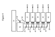
- a block diagram of a sampling rate converter is shown.
- Five different input signals 25 to 29 with an input sample rate FS1 are received and converted into a corresponding set of five output signals 30 to 34.
- the set of input signals 25 to 29 might for example be a set of five audio signals comprising a front left signal 25, a front right signal 26, a center signal 27, a rear left signal 28 and a rear right signal 29.
- the corresponding set of five output signals might comprise a front left signal 30, a front right signal 31, a center signal 32, a rear left signal 33, and a rear right signal 34.
- the set of input signals 25 to 29 might e.g. be an ensemble of audio signals that is received by a digital broadcast receiver, e.g. by a DAB receiver.
- the sampling rate converter comprises a rate converter control 35 for controlling a FIR filter calculation unit 36 and a set of convolution blocks 37 to 41.
- the rate converter control 35 determines, individually for each of the output samples, a corresponding fractional time delay between said output sample and a corresponding input sample.
- These fractional time delays 42 are provided to the FIR filter calculation unit 36, and there, a set of filter coefficients corresponding to the respectively required fractional time delay 42 is calculated.
- the derived set of filter coefficients 43 is provided to each of the convolution blocks 37 to 41. For each output sample to be generated, a convolution is performed by the respective convolution block.
- the sequences of filter coefficients 43 have to be correctly aligned with the stream of input samples.
- the rate converter control 35 transmits a control signal 44 to each of the convolution blocks 37 to 41, with said control signal 44 indicating the respective start sample where the convolution has to be started.
- These start samples can be determined from the time delay between an input sample and its corresponding output sample.
- Fig. 5A it is shown how the convolution is performed in case the output sample rate FS2 is larger than the input sample rate FS1: FS2 > FS1. In this case, the output samples of the output signal have to occur more frequently than the input samples of the input signal.
- the input signal 45 in the upper part of Fig. 5A comprises a sequence of input samples 46, 47, 48, ....
- a subset of the input samples is convoluted with a set 49 of filter coefficients 50 to 55, whereby the convolution is started at the input sample 46.
- the filter coefficients 50 to 55 have been calculated in accordance with the fractional time delay required for generating a first output sample.
- the time intervals between consecutive output samples are shorter than the time intervals between consecutive input samples. From time to time, it might therefore be necessary to start two consecutive convolutions at the same input sample.
- the input samples 47, 48, ... are convoluted with the set 59 of filter coefficients 60, 61, ....
- the thus generated third output sample does not coincide with the second output sample, though, because the filter coefficients 60, 61, ... correspond to a different fractional delay than the filter coefficients 57, 58, ....
- a fourth set 62 of filter coefficients is used for generating a fourth output sample.
- Fig. 5B shows the case of an output sample rate FS2 that is smaller than the input sample rate FS1: FS2 ⁇ FS1.
- a sequence 63 of input samples 64, 65, 66, 67, ... is convoluted with different sets 68, 69, 70, 71 of filter coefficients, in order to obtain a respective sequence of output samples.
- the first convolution is started at the input sample 64, and the second convolution is started at the input sample 65.
- the convolution for calculating the third output sample is started at the input sample 67.
Landscapes
- Physics & Mathematics (AREA)
- Engineering & Computer Science (AREA)
- Computer Hardware Design (AREA)
- Mathematical Physics (AREA)
- Filters That Use Time-Delay Elements (AREA)
Priority Applications (1)
| Application Number | Priority Date | Filing Date | Title |
|---|---|---|---|
| EP03005534A EP1458097A1 (de) | 2003-03-11 | 2003-03-11 | Beliebige Abtastratenkonversion |
Applications Claiming Priority (1)
| Application Number | Priority Date | Filing Date | Title |
|---|---|---|---|
| EP03005534A EP1458097A1 (de) | 2003-03-11 | 2003-03-11 | Beliebige Abtastratenkonversion |
Publications (1)
| Publication Number | Publication Date |
|---|---|
| EP1458097A1 true EP1458097A1 (de) | 2004-09-15 |
Family
ID=32748858
Family Applications (1)
| Application Number | Title | Priority Date | Filing Date |
|---|---|---|---|
| EP03005534A Withdrawn EP1458097A1 (de) | 2003-03-11 | 2003-03-11 | Beliebige Abtastratenkonversion |
Country Status (1)
| Country | Link |
|---|---|
| EP (1) | EP1458097A1 (de) |
Cited By (5)
| Publication number | Priority date | Publication date | Assignee | Title |
|---|---|---|---|---|
| WO2007095624A3 (en) * | 2006-02-15 | 2007-10-11 | Qualcomm Inc | Digital domain sampling rate converter |
| CN101800847A (zh) * | 2010-04-14 | 2010-08-11 | 蒲亦非 | 基于Riemann-Liouville定义的数字图像的1~2阶分数阶微分滤波器 |
| CN109164437A (zh) * | 2018-10-26 | 2019-01-08 | 海鹰企业集团有限责任公司 | 用于矢量阵列流行的连续可变小数时延估计方法及装置 |
| CN110266287A (zh) * | 2019-05-05 | 2019-09-20 | 深圳信息职业技术学院 | 电子耳蜗分数延迟滤波器构造方法、存储介质及电子耳蜗 |
| CN113986195A (zh) * | 2021-12-27 | 2022-01-28 | 中科南京智能技术研究院 | 一种延迟型单比特存内计算单元及装置 |
Citations (3)
| Publication number | Priority date | Publication date | Assignee | Title |
|---|---|---|---|---|
| EP0599817A1 (de) * | 1987-12-29 | 1994-06-01 | Sony Corporation | Verfahren zur Umsetzung der Bemusterungsfrequenz |
| WO1999060701A1 (en) * | 1998-05-18 | 1999-11-25 | Technische Universiteit Delft | Method and device for filtering a digital signal with fractional delay |
| EP1160979A2 (de) * | 2000-06-02 | 2001-12-05 | Texas Instruments Inc. | Abtastratenumwandler und Verfahren |
-
2003
- 2003-03-11 EP EP03005534A patent/EP1458097A1/de not_active Withdrawn
Patent Citations (3)
| Publication number | Priority date | Publication date | Assignee | Title |
|---|---|---|---|---|
| EP0599817A1 (de) * | 1987-12-29 | 1994-06-01 | Sony Corporation | Verfahren zur Umsetzung der Bemusterungsfrequenz |
| WO1999060701A1 (en) * | 1998-05-18 | 1999-11-25 | Technische Universiteit Delft | Method and device for filtering a digital signal with fractional delay |
| EP1160979A2 (de) * | 2000-06-02 | 2001-12-05 | Texas Instruments Inc. | Abtastratenumwandler und Verfahren |
Non-Patent Citations (2)
| Title |
|---|
| J.O.SMITH AND P. GOSSET: "A flexible sampling-rate conversion method", PROCEEDINGS OF THE INTERNATIONAL CONFERENCE ON AOUSTICS, SPEECH, AND SIGNAL PROCESSING, vol. 2, 1984, New York, pages 19.4.1 - 19.4.4, XP002252162 * |
| T.I.LAAKSO, V.VÄLIMÄKI, M.KARJALAINEN, U.K.LAINE: "Splitting the Unit Delay", IEEE SIGNAL PROCESSING MAGAZINE, 1996, pages 30 - 60, XP002252163 * |
Cited By (8)
| Publication number | Priority date | Publication date | Assignee | Title |
|---|---|---|---|---|
| WO2007095624A3 (en) * | 2006-02-15 | 2007-10-11 | Qualcomm Inc | Digital domain sampling rate converter |
| US7528745B2 (en) | 2006-02-15 | 2009-05-05 | Qualcomm Incorporated | Digital domain sampling rate converter |
| CN101800847A (zh) * | 2010-04-14 | 2010-08-11 | 蒲亦非 | 基于Riemann-Liouville定义的数字图像的1~2阶分数阶微分滤波器 |
| CN109164437A (zh) * | 2018-10-26 | 2019-01-08 | 海鹰企业集团有限责任公司 | 用于矢量阵列流行的连续可变小数时延估计方法及装置 |
| CN109164437B (zh) * | 2018-10-26 | 2021-03-16 | 海鹰企业集团有限责任公司 | 用于矢量阵列流行的连续可变小数时延估计方法及装置 |
| CN110266287A (zh) * | 2019-05-05 | 2019-09-20 | 深圳信息职业技术学院 | 电子耳蜗分数延迟滤波器构造方法、存储介质及电子耳蜗 |
| CN113986195A (zh) * | 2021-12-27 | 2022-01-28 | 中科南京智能技术研究院 | 一种延迟型单比特存内计算单元及装置 |
| CN113986195B (zh) * | 2021-12-27 | 2022-05-20 | 中科南京智能技术研究院 | 一种延迟型单比特存内计算单元及装置 |
Similar Documents
| Publication | Publication Date | Title |
|---|---|---|
| EP0695032B1 (de) | Digital/Digital-Abtastratenumsetzer | |
| US20040103133A1 (en) | Decimating filter | |
| US20030025619A1 (en) | System and method for increasing sample rate converter filter coefficient derivation speed | |
| JP2003069388A (ja) | ディジタル・フィルタ | |
| US7248189B2 (en) | Programmable sample rate conversion engine for wideband systems | |
| EP0612148B1 (de) | Als dreistufiges transversales Filter anwendbare digitale Filterschaltung | |
| Pei et al. | Fractional bilinear transform for analog-to-digital conversion | |
| US7411525B2 (en) | Sampling rate converting method and circuit | |
| EP0657999B1 (de) | Verfahren zur Umsetzung der Abtastfrequenz | |
| EP1176516A2 (de) | Rechnereinrichtung von einer rekursiven, diskreten Fourier-Transformation | |
| AU724637B2 (en) | Decimation method and decimation filter | |
| EP1458097A1 (de) | Beliebige Abtastratenkonversion | |
| Chan et al. | Design and complexity optimization of a new digital IF for software radio receivers with prescribed output accuracy | |
| CN119787987B (zh) | 一种软件无线电数字信号频率转换方法、系统及介质 | |
| US5821884A (en) | Sampling rate conversion method and apparatus utilizing an area effect correlation method | |
| US7225213B2 (en) | Interpolation filter and method for digitally interpolating a digital signal | |
| US5838956A (en) | Clock generating circuit | |
| US7327288B2 (en) | Variable interpolator for non-uniformly sampled signals and method | |
| JP2008219560A (ja) | デシメーションフィルタ | |
| JPH0555875A (ja) | デイジタルフイルタ | |
| KR100587309B1 (ko) | 디지털 보간 필터 | |
| JPH0453307A (ja) | 標本化周波数変換器 | |
| CN111884655B (zh) | 一种可变模小数变频的串行信号处理方法及装置 | |
| JP3258938B2 (ja) | デシメーションフィルタ | |
| KR0176205B1 (ko) | 고역통과 iir 필터의 설계방법 및 이에 적합한 고역통과 iir 필터 |
Legal Events
| Date | Code | Title | Description |
|---|---|---|---|
| PUAI | Public reference made under article 153(3) epc to a published international application that has entered the european phase |
Free format text: ORIGINAL CODE: 0009012 |
|
| AK | Designated contracting states |
Kind code of ref document: A1 Designated state(s): AT BE BG CH CY CZ DE DK EE ES FI FR GB GR HU IE IT LI LU MC NL PT SE SI SK TR |
|
| AX | Request for extension of the european patent |
Extension state: AL LT LV MK RO |
|
| AKX | Designation fees paid | ||
| REG | Reference to a national code |
Ref country code: DE Ref legal event code: 8566 |
|
| STAA | Information on the status of an ep patent application or granted ep patent |
Free format text: STATUS: THE APPLICATION IS DEEMED TO BE WITHDRAWN |
|
| 18D | Application deemed to be withdrawn |
Effective date: 20050316 |