EP1459831A2 - Für einen TIG Roboterschweissbrenner hergestelle Düsen/Drahtführungsanordnung - Google Patents
Für einen TIG Roboterschweissbrenner hergestelle Düsen/Drahtführungsanordnung Download PDFInfo
- Publication number
- EP1459831A2 EP1459831A2 EP04300144A EP04300144A EP1459831A2 EP 1459831 A2 EP1459831 A2 EP 1459831A2 EP 04300144 A EP04300144 A EP 04300144A EP 04300144 A EP04300144 A EP 04300144A EP 1459831 A2 EP1459831 A2 EP 1459831A2
- Authority
- EP
- European Patent Office
- Prior art keywords
- nozzle
- wire
- torch
- wire guide
- electrode
- Prior art date
- Legal status (The legal status is an assumption and is not a legal conclusion. Google has not performed a legal analysis and makes no representation as to the accuracy of the status listed.)
- Granted
Links
Images
Classifications
-
- B—PERFORMING OPERATIONS; TRANSPORTING
- B23—MACHINE TOOLS; METAL-WORKING NOT OTHERWISE PROVIDED FOR
- B23K—SOLDERING OR UNSOLDERING; WELDING; CLADDING OR PLATING BY SOLDERING OR WELDING; CUTTING BY APPLYING HEAT LOCALLY, e.g. FLAME CUTTING; WORKING BY LASER BEAM
- B23K9/00—Arc welding or cutting
- B23K9/16—Arc welding or cutting making use of shielding gas
- B23K9/167—Arc welding or cutting making use of shielding gas and of a non-consumable electrode
-
- B—PERFORMING OPERATIONS; TRANSPORTING
- B23—MACHINE TOOLS; METAL-WORKING NOT OTHERWISE PROVIDED FOR
- B23K—SOLDERING OR UNSOLDERING; WELDING; CLADDING OR PLATING BY SOLDERING OR WELDING; CUTTING BY APPLYING HEAT LOCALLY, e.g. FLAME CUTTING; WORKING BY LASER BEAM
- B23K9/00—Arc welding or cutting
- B23K9/24—Features related to electrodes
- B23K9/28—Supporting devices for electrodes
- B23K9/29—Supporting devices adapted for making use of shielding means
- B23K9/291—Supporting devices adapted for making use of shielding means the shielding means being a gas
Definitions
- the present invention relates to an automatic TIG welding torch with integrated fuse wire supply dedicated to robotic welding.
- a TIG welding torch for Tungsten Inert Gas fed with welding wire is conventionally in the form of a one-piece body with internal arrangements specific to the implementation of the welding process to which this torch is dedicated.
- the torches can be straight or bent, that is to say that the beam goes in the axis of the torch for a straight torch or perpendicular to the axis of the torch for a bent torch.
- torch support or base In the rear part of the torch, commonly called torch support or base, there are flexible or semi-rigid fluid supply lines which are connected to the torch body by a connection system specific to each type of pipe.
- the power supply cables are mechanically assembled most often by screwing to the corresponding circuits of the torch, except in the case of cables cooled by liquid or gas which then have a suitable attachment.
- a flexible tubular sheath attached to the back of the torch by a collar or the like, groups together the bundle of cables so as to protect it.
- the front part of the torch also called the torch body, comprises a nozzle or nozzle for channeling the shielding gas, which nozzle is fixed to the torch body by screwing or other clamping system or the like, and an electrode .
- the nozzle may be metallic and cooled or not by a cooling fluid, such as water or a gas; in this case, it must be electrically isolated from the torch body.
- a cooling fluid such as water or a gas
- the nozzle may also be made of a suitable insulating material uncooled, for example ceramic.
- the electrode usually made of pure or thoriated tungsten is kept centered in the torch body, by a clamp system or the like, so that the nozzle comes to form a sleeve around the electrode.
- a fuse wire supply system is generally arranged independently of the torch, that is to say, it is fixed integrally to the torch body or the torch support, the support of the torch being the organ that binds the torch to its displacement device.
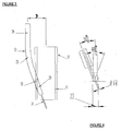
- the filler wire is fed into the welding bath by the supply system 3 tangentially or quasi-tangentially to the liquid metal, behind the electrode 2 surrounded by the nozzle 1, depending on the welding direction.
- the angle B defined by the electrode 2 and the filler wire 3 is around 85 ° to 90 °.
- This operation obliges the operator to stop the machine, disassemble the electrode, sharpen or replace it, then reassemble it and, finally, fine-tune the respective positions of the electrode and wire so find the precise position of the wire at the back of the electrode and tangentially to the welding joint.
- the object of the invention is to provide a new TIG welding torch architecture with filler wire that allows easy and accurate positioning of the wire relative to the electrode.
- the solution of the invention is a nozzle / guide-wire assembly for an arc welding torch comprising at least one nozzle for delivering gas and at least one guide-wire system for guiding at least one fusible wire, characterized in that the downstream end of the wire guide system opens into the interior of the nozzle.
- the invention also relates to a TIG welding torch equipped with such a nozzle / guide-wire assembly.
- the torch compote, in addition, a non-fusible electrode arranged in such a manner with respect to the nozzle / guide-wire assembly that the wire conveyed by the wire guide penetrates into the nozzle, towards the electrode, at an angle between 5 ° and 50 °, preferably between 10 and 30 °, relative to the axis of the electrode or the nozzle, the wire and the electrode being in the same plane.
- the torch also comprises a base on which is fixed the nozzle / guide-wire assembly in a pre-defined position.
- the invention relates to a robotic welding installation comprising at least one robotic arm provided with such a torch.
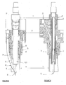
- An arc welding torch consists of three main subassemblies, namely a torch holder or base 27, a torch body 16 and a nozzle 11 incorporating a wire guide system 13 forming an assembly. monobloc nozzle / wire guide.
- the torch holder or base supports all fluid inflows, including the arrival and return of coolant (water); the arrival of the gas or gases necessary for carrying out the welding process; the connection of the electrical power via one or more power supply cables, solid or cooled by liquid or gas, their method of attachment being a function of the cable considered; and the arrival of the guiding sheath of the filler wire, the latter arriving parallel to the geometric axis of the torch defined by the electrode.
- the base 27 is fixed to the wrist of a robot installation by means of a suitable mechanical element, itself taken on an "anti-shock" safety device.
- the base 27 receives, on the one hand, the torch body subassembly 16 to which it distributes the fluidic elements, that is to say the gas and the cooling water, as well as the electric power by the intermediate of a contact socket intended to ensure the electrical contact necessary for carrying out the welding process and, on the other hand, the nozzle subassembly 11 / wire guide 13 to which it delivers the filler metal, that is to say the wire 14 fuse welding.
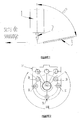
- the design of the base 27 allows a positioning of the nozzle subassembly 11 / wire guide 13 concentrically to the subassembly body 16 torch according to a position 30 chosen beforehand depending on the welding operation to be performed, these different positions 30 being distributed over a ring of 270 °, as shown schematically in FIG.
- the torch body 16 receives the electrode 12 in pure or thoriated tungsten, made in a cylindrical sintered tungsten rod sharpened at one of its ends.
- the electrode 12 is held centered by a conventional holding system, such as a push or pull clamp system, an interlocking system or the like.
- the electrode 12 may also be composed of two elements, namely a copper alloy support supporting a piece of pure tungsten or thorium force-fitted, crimped or soldered. In this case, the electrode then becomes a consumable that is replaced when worn.
- the torch body 16 can be cooled or not by means of circuits (passage 23) of coolant coming from the torch holder.
- the torch body 16 may also be equipped with an additional central gas circuit, it is then equipped with an external nozzle arranged around the nozzle 11 to implement a TIG process of the double flow type.
- the torch body 16 is introduced into the torch holder or base 27 in abutment (at 30) on a shoulder 31 of said torch body 16, which shoulder 31 serves as a reference position along the Z axis.
- a suitable mechanical device to hold it in position, for example a screw ring, a pin system or the like.
- the nozzle assembly 1 1 / wire guide 13 consists of a nozzle 11 and a wire guide system 13 secured to one another, for example by brazing, screwing, gluing or welding.
- the nozzle 11 is a generally cylindrical hollow metal element, which may or may not be cooled by a coolant from the torch holder 27 according to the power of the torch.
- the nozzle 11 is fixed on the torch support 27 concentrically to the torch body 16 from which it is electrically isolated.
- An axial adjustment device 15 allows the nozzle 11 / wire guide 13 to be accurately positioned relative to the electrode 12.
- the adjusting device 15 comprises, for example, a threaded ring 15 cooperating with a part 18. the torch body 16 and a thread 17 carried by the outer peripheral wall of the upstream end of the nozzle 11.
- the nozzle 11 receives the wire guide 13 for conveying the welding wire 14.
- the wire guide 13 is in the form of a tubular element whose inner diameter is a function of the diameter of the wire 14 used.
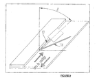
- the wire guide 13 extends outside the nozzle 11 at a small distance D from said nozzle 11 while being positioned parallel thereto, typically at a distance D less than or equal to approximately 30 mm, as shown in FIG. 3.
- the distance D is the distance separating the axis of the nozzle 11 from the axis of the tube 13 considered outside the nozzle 11 at the portion of the wire guide 13 which is parallel or quasi-parallel (part 24) to the the axis of the nozzle 11, as visible in FIG.
- the tubular element 13 for conveying the wire is bent (part 25) in a sufficient radius so as to allow the passage to semi-rigid yarns and this, without jamming or excessive friction, and is further profiled at its downstream end facing the electrode 12.
- the wire guide 13 is introduced into the nozzle 11 by a housing or recess 10 machined so that the wire 14 enters the nozzle 11, towards the electrode 12, at a preferred angle between 10 ° and 30 °. ° with respect to the axis passing through the electrode 12 or the nozzle 11, the wire 14 and the electrode 12 being in the same plane.
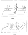
- the geometry of the nozzle assembly 11 / wire guide 13 is such that the end portion is minimal, that is to say the unguided portion of the wire at its output from the wire guide as shown in FIG. downstream end 20 of the wire guide 13 must in no case come into mechanical contact with the electrode 12 or the torch body 16, as shown in Figures 3 and 4.
- the end of the filler wire 14 comes into the anode spot 22 created by the electric arc, during the implementation of the TIG process, regardless of the arc voltage obtained for a gas corresponding to a working height. given.
- the filler wire 14 must be distributed in such a way that the end of said wire 14 comes to graze, that is to say approaches the end of the sharpened electrode 12 at a distance which must not preferably, be smaller than the diameter of the filler wire 14.
- the torch of the invention is therefore in one-piece form, that is to say a TIG torch with wire guide system 13 partially integrated with the nozzle 11, and therefore does not require a complementary axis for guiding the 14 wire relative to the joint plane to achieve, which makes it very convenient to integrate on a robotic welding arm.
- the preset of the electrode 12 in the electrode holder 19 and the adjustment of the nozzle 11 with integrated wire guide 13 makes it possible to guarantee precise positioning of the wire 14 with respect to the electrode 12 so that it happens always in the anodic spot of the bow.
- the preset electrode holder 19 allows a quick change of this module without the need for registration along the Z axis of the robot.
- the electrode holder 19 may be arranged so as to protect the electrode 12 with a shielding gas and thus ensure operating conditions similar to those of a TIG welding process under concentric double flows of gas.
- the torch can operate in self-regulation of arc voltage, the latter being provided directly by the robot.
- it can also be equipped with an industrial tracking system of mechanical or optical type, for example by laser with CCD camera (Charged Coupled Device).
- CCD camera Charged Coupled Device
- the wire reeling device can be made in a continuous or alternative manner depending on the applications and technologies available.
- the current delivered by the welding source may be a pulsed or unpowered continuous current for carbon or stainless steels, nickel, titanium-zirconium and tantalum bases, or an alternating current or variable polarity for welding light alloys based on aluminum or magnesium.
- the unwinding of the filler wire 14 used in the torch can be continuous or pulsed by a clocked movement for example by a mechanical device type rod, crank or other, or an electronic control device of the unwinding motor.
- the design of the torch of the invention allows operation in TIG welding process of single or double gas flow type.
- the welding torch of the invention can be used to assemble by welding or brazing various sheet elements of variable thickness ranging from 0.5 mm to 4 mm carbon steel, uncoated and coated (electrogalvanized or galvanized) , in ferritic or austenitic stainless steel, in aluminum or magnesium light alloy.
- the filler wire may be, depending on the intended use, unalloyed or low-alloyed steel, ferritic or austenitic stainless steel, nickel or nickel alloy, pure copper or copper alloy, aluminum or aluminum alloy. aluminum.
- the welding torch of the invention is designed so as to be able to equip an automated welding robot for welding a wide variety of elements or parts, especially parts intended for the automotive industry, in particular crates or body elements, hoods , doors, aluminum or aluminum alloy floor systems, ferritic or austenitic stainless steel exhaust systems, but also to other industries such as the motorcycle industry, particularly for welding bicycle frames into aluminum or aluminum alloys, or to make scaffolding or ladders made of steel or light alloys.
- the torch of the invention is more generally used for the implementation of any welding operation that requires obtaining a beautiful appearance of welding bead.
Landscapes
- Engineering & Computer Science (AREA)
- Physics & Mathematics (AREA)
- Plasma & Fusion (AREA)
- Mechanical Engineering (AREA)
- Arc Welding In General (AREA)
- Butt Welding And Welding Of Specific Article (AREA)
Priority Applications (1)
| Application Number | Priority Date | Filing Date | Title |
|---|---|---|---|
| PL04300144T PL1459831T3 (pl) | 2003-03-17 | 2004-03-15 | Sposób spawania TIG ze zrobotyzowanym palnikiem spawalniczym TIG zawierającym zespół dysza/podajnik drutu. |
Applications Claiming Priority (2)
| Application Number | Priority Date | Filing Date | Title |
|---|---|---|---|
| FR0303237A FR2852540B1 (fr) | 2003-03-17 | 2003-03-17 | Ensemble buse/guide-fil pour torche de soudage tig robotise |
| FR0303237 | 2003-03-17 |
Publications (3)
| Publication Number | Publication Date |
|---|---|
| EP1459831A2 true EP1459831A2 (de) | 2004-09-22 |
| EP1459831A3 EP1459831A3 (de) | 2004-12-22 |
| EP1459831B1 EP1459831B1 (de) | 2006-04-26 |
Family
ID=32799674
Family Applications (1)
| Application Number | Title | Priority Date | Filing Date |
|---|---|---|---|
| EP04300144A Expired - Lifetime EP1459831B1 (de) | 2003-03-17 | 2004-03-15 | Verfahren zum TIG-Schweissen mit einem eine Düsen/Drahtführungsanordnung aufweisenden TIG-Roboterschweissbrenner |
Country Status (8)
| Country | Link |
|---|---|
| US (1) | US7078646B2 (de) |
| EP (1) | EP1459831B1 (de) |
| AT (1) | ATE324216T1 (de) |
| DE (1) | DE602004000718T2 (de) |
| ES (1) | ES2264100T3 (de) |
| FR (1) | FR2852540B1 (de) |
| PL (1) | PL1459831T3 (de) |
| PT (1) | PT1459831E (de) |
Cited By (8)
| Publication number | Priority date | Publication date | Assignee | Title |
|---|---|---|---|---|
| EP1736270A1 (de) | 2005-06-22 | 2006-12-27 | L'air Liquide, Societe Anonyme Pour L'etude Et L'exploitation Des Procedes Georges Claude | WIG-Schweiss- bzw, Lötverfahren mit Metallübertragung durch eine flüssigmetallbrücke |
| WO2008015353A1 (fr) * | 2006-08-03 | 2008-02-07 | L'air Liquide Societe Anonyme Pour L'etude Et L'exploitation Des Procedes Georges Claude | Soudo-brasage tig avec transfert de metal par gouttes a frequence controlee |
| FR2956053A1 (fr) * | 2010-02-11 | 2011-08-12 | Air Liquide | Dispositif et procede de soudage a l'arc |
| US8367962B2 (en) | 2007-10-26 | 2013-02-05 | Ariel Andre Waitzman | Automated welding of moulds and stamping tools |
| WO2015067882A1 (fr) | 2013-11-07 | 2015-05-14 | L'air Liquide, Societe Anonyme Pour L'etude Et L'exploitation Des Procedes Georges Claude | Procede de rechargement a l'arc electrique avec protection gazeuse constitue d'un melange gazeux argon/helium |
| US9292016B2 (en) | 2007-10-26 | 2016-03-22 | Ariel Andre Waitzman | Automated welding of moulds and stamping tools |
| US9776274B2 (en) | 2007-10-26 | 2017-10-03 | Ariel Andre Waitzman | Automated welding of moulds and stamping tools |
| WO2022035821A2 (en) | 2020-08-12 | 2022-02-17 | The Esab Group Inc. | Arc welding, cladding, and additive manufacturing method and apparatus |
Families Citing this family (11)
| Publication number | Priority date | Publication date | Assignee | Title |
|---|---|---|---|---|
| US7329827B2 (en) * | 2004-03-11 | 2008-02-12 | L'air Liquide, Societe Anonyme A Directoire Et Conseil De Surveillance Pour L'etude Et L'exploitation Des Procedes Georges Claude | Wire-guide nozzle assembly for a robotic TIG welding torch |
| US8026456B2 (en) * | 2007-02-20 | 2011-09-27 | Illinois Tool Works Inc. | TIG welding system and method |
| US9132500B2 (en) | 2012-07-10 | 2015-09-15 | Illinois Tool Works Inc. | Methods and systems for feeding filler material to a welding operation |
| US9962785B2 (en) * | 2013-12-12 | 2018-05-08 | Lincoln Global, Inc. | System and method for true electrode speed |
| US20160346867A1 (en) * | 2014-02-11 | 2016-12-01 | John Hill | Method Of Joining Dissimilar Materials |
| DE102014002213B4 (de) * | 2014-02-21 | 2016-01-14 | MHIW b.v. | Verfahren und Brennerkopf zum Metall-Schutzgas-Schweißen |
| EP3165314A1 (de) * | 2015-11-06 | 2017-05-10 | Siegfried Plasch | Auftragsschweissverfahren |
| CN107775158A (zh) * | 2016-08-25 | 2018-03-09 | 北京文源同创科技有限公司 | 一种焊枪 |
| US11673204B2 (en) | 2020-11-25 | 2023-06-13 | The Esab Group, Inc. | Hyper-TIG welding electrode |
| DE102021116340A1 (de) | 2021-06-24 | 2022-12-29 | Bayerische Motoren Werke Aktiengesellschaft | Schweißelektrodeneinheit zum Schutzgasschweißen sowie Schweißbrenner zum Schutzgasschweißen |
| CN113664345A (zh) * | 2021-09-06 | 2021-11-19 | 潍坊新松机器人自动化有限公司 | 一种双丝焊接机器人工作站 |
Family Cites Families (14)
| Publication number | Priority date | Publication date | Assignee | Title |
|---|---|---|---|---|
| US2791673A (en) * | 1954-05-25 | 1957-05-07 | Air Liquide | Process and device for electric arc welding in a protective atmosphere |
| US3588464A (en) * | 1969-04-17 | 1971-06-28 | Union Carbide Corp | Dual electrode torch for manual welding |
| US3617688A (en) * | 1969-07-29 | 1971-11-02 | Ssp Ind | Tack welding torch |
| US4233489A (en) * | 1974-03-25 | 1980-11-11 | U.S. Philips Corporation | Method of and device for plasma MIG-welding |
| US4531040A (en) * | 1982-01-11 | 1985-07-23 | Mitsubishi Denki K.K. | Hot wire type arc welding torch and cable |
| US4532406A (en) * | 1984-02-10 | 1985-07-30 | General Electric Company | Arc welding torch having integrated wire feed |
| DE3542984A1 (de) | 1985-12-05 | 1987-06-11 | Stk Ges Fuer Schweisstechnik M | Verfahren und einrichtung zum teil- oder vollmechanisierten schutzgas-verbindungsschweissen |
| US4879446A (en) * | 1988-12-05 | 1989-11-07 | The United States Of America As Represented By The Administrator Of The National Aeronautics And Space Administration | Internal wire guide for GTAW welding |
| US4924053A (en) * | 1988-12-05 | 1990-05-08 | The United States Of America As Represented By The Administrator Of The National Aeronautics And Space Administration | Electrode carrying wire for GTAW welding |
| FR2717724B1 (fr) * | 1994-03-24 | 1996-04-26 | Snecma | Installation de soudage automatique. |
| FR2723330B1 (fr) * | 1994-08-03 | 1996-10-31 | Maltzeff Yves | Appareillage portatif perfectionne de soudure electrique sous atmosphere gazeuse |
| US5793009A (en) * | 1996-06-20 | 1998-08-11 | General Electric Company | Apparatus for joining metal components using broad, thin filler nozzle |
| JPH11104839A (ja) * | 1997-09-30 | 1999-04-20 | Komatsu Ltd | アーク溶接トーチ |
| JPH11104841A (ja) * | 1997-10-01 | 1999-04-20 | Komatsu Ltd | 非消耗電極溶接トーチ並びにプラズマ溶接トーチ及びその外側キャップ |
-
2003
- 2003-03-17 FR FR0303237A patent/FR2852540B1/fr not_active Expired - Fee Related
-
2004
- 2004-03-11 US US10/798,761 patent/US7078646B2/en not_active Expired - Lifetime
- 2004-03-15 EP EP04300144A patent/EP1459831B1/de not_active Expired - Lifetime
- 2004-03-15 AT AT04300144T patent/ATE324216T1/de not_active IP Right Cessation
- 2004-03-15 ES ES04300144T patent/ES2264100T3/es not_active Expired - Lifetime
- 2004-03-15 PT PT04300144T patent/PT1459831E/pt unknown
- 2004-03-15 DE DE602004000718T patent/DE602004000718T2/de not_active Expired - Lifetime
- 2004-03-15 PL PL04300144T patent/PL1459831T3/pl unknown
Cited By (13)
| Publication number | Priority date | Publication date | Assignee | Title |
|---|---|---|---|---|
| EP1736270A1 (de) | 2005-06-22 | 2006-12-27 | L'air Liquide, Societe Anonyme Pour L'etude Et L'exploitation Des Procedes Georges Claude | WIG-Schweiss- bzw, Lötverfahren mit Metallübertragung durch eine flüssigmetallbrücke |
| EP1736270B2 (de) † | 2005-06-22 | 2010-10-20 | L'AIR LIQUIDE, Société Anonyme pour l'Etude et l'Exploitation des Procédés Georges Claude | WIG-Schweiss- bzw, Lötverfahren mit Metallübertragung durch eine flüssigmetallbrücke |
| WO2008015353A1 (fr) * | 2006-08-03 | 2008-02-07 | L'air Liquide Societe Anonyme Pour L'etude Et L'exploitation Des Procedes Georges Claude | Soudo-brasage tig avec transfert de metal par gouttes a frequence controlee |
| FR2904576A1 (fr) * | 2006-08-03 | 2008-02-08 | Air Liquide | Soudo-brasage tig avec transfert de metal par gouttes et a frequence controlee |
| US8367962B2 (en) | 2007-10-26 | 2013-02-05 | Ariel Andre Waitzman | Automated welding of moulds and stamping tools |
| US8857697B2 (en) | 2007-10-26 | 2014-10-14 | Ariel Andre Waitzman | Automated welding of moulds and stamping tools |
| US9292016B2 (en) | 2007-10-26 | 2016-03-22 | Ariel Andre Waitzman | Automated welding of moulds and stamping tools |
| US9776274B2 (en) | 2007-10-26 | 2017-10-03 | Ariel Andre Waitzman | Automated welding of moulds and stamping tools |
| US10279413B2 (en) | 2007-10-26 | 2019-05-07 | Ariel Andre Waitzman | Automated welding of moulds and stamping tools |
| EP2357055A1 (de) | 2010-02-11 | 2011-08-17 | L'AIR LIQUIDE, Société Anonyme pour l'Etude et l'Exploitation des Procédés Georges Claude | Verfahren zum WIG-Schweissen mit schmelzbarem Draht in einer Engnaht unter Verwendung eines magnetischen Felds |
| FR2956053A1 (fr) * | 2010-02-11 | 2011-08-12 | Air Liquide | Dispositif et procede de soudage a l'arc |
| WO2015067882A1 (fr) | 2013-11-07 | 2015-05-14 | L'air Liquide, Societe Anonyme Pour L'etude Et L'exploitation Des Procedes Georges Claude | Procede de rechargement a l'arc electrique avec protection gazeuse constitue d'un melange gazeux argon/helium |
| WO2022035821A2 (en) | 2020-08-12 | 2022-02-17 | The Esab Group Inc. | Arc welding, cladding, and additive manufacturing method and apparatus |
Also Published As
| Publication number | Publication date |
|---|---|
| FR2852540A1 (fr) | 2004-09-24 |
| US7078646B2 (en) | 2006-07-18 |
| ES2264100T3 (es) | 2006-12-16 |
| FR2852540B1 (fr) | 2005-04-29 |
| DE602004000718D1 (de) | 2006-06-01 |
| EP1459831A3 (de) | 2004-12-22 |
| DE602004000718T2 (de) | 2007-04-26 |
| EP1459831B1 (de) | 2006-04-26 |
| PL1459831T3 (pl) | 2006-09-29 |
| PT1459831E (pt) | 2006-09-29 |
| US20040195212A1 (en) | 2004-10-07 |
| ATE324216T1 (de) | 2006-05-15 |
Similar Documents
| Publication | Publication Date | Title |
|---|---|---|
| EP1459831B1 (de) | Verfahren zum TIG-Schweissen mit einem eine Düsen/Drahtführungsanordnung aufweisenden TIG-Roboterschweissbrenner | |
| US7485826B2 (en) | Wire-guide nozzle assembly for a robotic TIG welding torch | |
| EP1736270B2 (de) | WIG-Schweiss- bzw, Lötverfahren mit Metallübertragung durch eine flüssigmetallbrücke | |
| EP0819495B1 (de) | Vorrichtung zum Verbinden metallischer Bauteile mit einer breiten dünnen Zusatzdüse | |
| EP2457682B1 (de) | Schweißbrenner und Schweißroboter | |
| US9375801B2 (en) | Rotary welding torch | |
| EP2802435B1 (de) | Mig/wig oder mag/wig hybrid-schweissvorrichtung | |
| JP2009518190A (ja) | 溶接トーチ並びに溶接トーチ用末端部材および接触チューブ | |
| EP2051831A1 (de) | Wig-löt-schweissung mit metallübertragung in tropfenform mit gesteuerter frequenz | |
| CA2480569C (fr) | Ensemble buse/guide-fil pour torche de soudage tig robotise | |
| FR3012759A3 (fr) | Systeme pour et procede de soudage et/ou de rechargement avec fil additionnel | |
| EP3890913B1 (de) | Schweissbrenner und entsprechendes herstellungsverfahren | |
| JP5095910B2 (ja) | ロボットtig溶接のためのワイヤガイド/ノズルアッセンブリ | |
| JPH0118829B2 (de) | ||
| FR2986451A1 (fr) | Procede de soudage mig ou mag avec balayage plongeant de la torche | |
| EP0635330B1 (de) | Verkleinerter T.I.G. Schweissbrenner mit verbesserten Wirkungsgrad | |
| FR2818923A1 (fr) | Procede pour assurer une operation de traitement sur une torche de soudage notamment du type mig/mag et installation de soudage en faisant application | |
| EP0974416A1 (de) | Lichtbogenschweissdüse mit besonderen Durchmesser und Dicke | |
| JPH1071471A (ja) | 溶接用トーチ | |
| US20200055137A1 (en) | Precision Wire Guide For A Welding Consumable | |
| FR2996792A1 (fr) | Torche de coupage a plasma d'arc a assemblage ameliore | |
| TR2021014079A2 (tr) | Gazalti kaynaklar i̇çi̇n kontak memesi̇ | |
| KR20200119012A (ko) | Tig 용접용 텅스텐 전극봉 | |
| FR2941160A1 (fr) | Torche de soudage a l'arc des preparations de joints etroits | |
| FR2974526A1 (fr) | Dispositif et procede de soudage mig/mag |
Legal Events
| Date | Code | Title | Description |
|---|---|---|---|
| PUAI | Public reference made under article 153(3) epc to a published international application that has entered the european phase |
Free format text: ORIGINAL CODE: 0009012 |
|
| 17P | Request for examination filed |
Effective date: 20040315 |
|
| AK | Designated contracting states |
Kind code of ref document: A2 Designated state(s): AT BE BG CH CY CZ DE DK EE ES FI FR GB GR HU IE IT LI LU MC NL PL PT RO SE SI SK TR |
|
| AX | Request for extension of the european patent |
Extension state: AL HR LT LV MK |
|
| PUAL | Search report despatched |
Free format text: ORIGINAL CODE: 0009013 |
|
| AK | Designated contracting states |
Kind code of ref document: A3 Designated state(s): AT BE BG CH CY CZ DE DK EE ES FI FR GB GR HU IE IT LI LU MC NL PL PT RO SE SI SK TR |
|
| AX | Request for extension of the european patent |
Extension state: AL HR LT LV MK |
|
| 17Q | First examination report despatched |
Effective date: 20050309 |
|
| GRAP | Despatch of communication of intention to grant a patent |
Free format text: ORIGINAL CODE: EPIDOSNIGR1 |
|
| RTI1 | Title (correction) |
Free format text: PROCESS OF TIG WELDING WITH A A ROBOTIC TIG WELDING TORCH HAVING A NOZZLE/WIRE GUIDE ASSEMBLY |
|
| AKX | Designation fees paid |
Designated state(s): AT BE BG CH CY CZ DE DK EE ES FI FR GB GR HU IE IT LI LU MC NL PL PT RO SE SI SK TR |
|
| GRAS | Grant fee paid |
Free format text: ORIGINAL CODE: EPIDOSNIGR3 |
|
| GRAA | (expected) grant |
Free format text: ORIGINAL CODE: 0009210 |
|
| AK | Designated contracting states |
Kind code of ref document: B1 Designated state(s): AT BE BG CH CY CZ DE DK EE ES FI FR GB GR HU IE IT LI LU MC NL PL PT RO SE SI SK TR |
|
| PG25 | Lapsed in a contracting state [announced via postgrant information from national office to epo] |
Ref country code: IT Free format text: LAPSE BECAUSE OF FAILURE TO SUBMIT A TRANSLATION OF THE DESCRIPTION OR TO PAY THE FEE WITHIN THE PRESCRIBED TIME-LIMIT;WARNING: LAPSES OF ITALIAN PATENTS WITH EFFECTIVE DATE BEFORE 2007 MAY HAVE OCCURRED AT ANY TIME BEFORE 2007. THE CORRECT EFFECTIVE DATE MAY BE DIFFERENT FROM THE ONE RECORDED. Effective date: 20060426 Ref country code: FI Free format text: LAPSE BECAUSE OF FAILURE TO SUBMIT A TRANSLATION OF THE DESCRIPTION OR TO PAY THE FEE WITHIN THE PRESCRIBED TIME-LIMIT Effective date: 20060426 Ref country code: IE Free format text: LAPSE BECAUSE OF FAILURE TO SUBMIT A TRANSLATION OF THE DESCRIPTION OR TO PAY THE FEE WITHIN THE PRESCRIBED TIME-LIMIT Effective date: 20060426 Ref country code: AT Free format text: LAPSE BECAUSE OF FAILURE TO SUBMIT A TRANSLATION OF THE DESCRIPTION OR TO PAY THE FEE WITHIN THE PRESCRIBED TIME-LIMIT Effective date: 20060426 Ref country code: SI Free format text: LAPSE BECAUSE OF FAILURE TO SUBMIT A TRANSLATION OF THE DESCRIPTION OR TO PAY THE FEE WITHIN THE PRESCRIBED TIME-LIMIT Effective date: 20060426 |
|
| REG | Reference to a national code |
Ref country code: GB Ref legal event code: FG4D Free format text: NOT ENGLISH |
|
| REG | Reference to a national code |
Ref country code: IE Ref legal event code: FG4D Free format text: LANGUAGE OF EP DOCUMENT: FRENCH |
|
| REF | Corresponds to: |
Ref document number: 602004000718 Country of ref document: DE Date of ref document: 20060601 Kind code of ref document: P |
|
| REG | Reference to a national code |
Ref country code: RO Ref legal event code: EPE |
|
| PG25 | Lapsed in a contracting state [announced via postgrant information from national office to epo] |
Ref country code: DK Free format text: LAPSE BECAUSE OF FAILURE TO SUBMIT A TRANSLATION OF THE DESCRIPTION OR TO PAY THE FEE WITHIN THE PRESCRIBED TIME-LIMIT Effective date: 20060726 |
|
| REG | Reference to a national code |
Ref country code: CH Ref legal event code: NV Representative=s name: SUSI PRYDE-HAENI BSC |
|
| REG | Reference to a national code |
Ref country code: SE Ref legal event code: TRGR |
|
| GBT | Gb: translation of ep patent filed (gb section 77(6)(a)/1977) |
Effective date: 20060727 |
|
| REG | Reference to a national code |
Ref country code: PT Ref legal event code: SC4A Effective date: 20060726 |
|
| REG | Reference to a national code |
Ref country code: IE Ref legal event code: FD4D |
|
| REG | Reference to a national code |
Ref country code: ES Ref legal event code: FG2A Ref document number: 2264100 Country of ref document: ES Kind code of ref document: T3 |
|
| PLBE | No opposition filed within time limit |
Free format text: ORIGINAL CODE: 0009261 |
|
| STAA | Information on the status of an ep patent application or granted ep patent |
Free format text: STATUS: NO OPPOSITION FILED WITHIN TIME LIMIT |
|
| 26N | No opposition filed |
Effective date: 20070129 |
|
| PG25 | Lapsed in a contracting state [announced via postgrant information from national office to epo] |
Ref country code: MC Free format text: LAPSE BECAUSE OF NON-PAYMENT OF DUE FEES Effective date: 20070331 |
|
| PG25 | Lapsed in a contracting state [announced via postgrant information from national office to epo] |
Ref country code: GR Free format text: LAPSE BECAUSE OF FAILURE TO SUBMIT A TRANSLATION OF THE DESCRIPTION OR TO PAY THE FEE WITHIN THE PRESCRIBED TIME-LIMIT Effective date: 20060727 |
|
| PG25 | Lapsed in a contracting state [announced via postgrant information from national office to epo] |
Ref country code: BG Free format text: LAPSE BECAUSE OF FAILURE TO SUBMIT A TRANSLATION OF THE DESCRIPTION OR TO PAY THE FEE WITHIN THE PRESCRIBED TIME-LIMIT Effective date: 20060726 |
|
| PG25 | Lapsed in a contracting state [announced via postgrant information from national office to epo] |
Ref country code: EE Free format text: LAPSE BECAUSE OF FAILURE TO SUBMIT A TRANSLATION OF THE DESCRIPTION OR TO PAY THE FEE WITHIN THE PRESCRIBED TIME-LIMIT Effective date: 20060426 |
|
| PG25 | Lapsed in a contracting state [announced via postgrant information from national office to epo] |
Ref country code: CY Free format text: LAPSE BECAUSE OF FAILURE TO SUBMIT A TRANSLATION OF THE DESCRIPTION OR TO PAY THE FEE WITHIN THE PRESCRIBED TIME-LIMIT Effective date: 20060426 Ref country code: LU Free format text: LAPSE BECAUSE OF NON-PAYMENT OF DUE FEES Effective date: 20070315 |
|
| PG25 | Lapsed in a contracting state [announced via postgrant information from national office to epo] |
Ref country code: HU Free format text: LAPSE BECAUSE OF FAILURE TO SUBMIT A TRANSLATION OF THE DESCRIPTION OR TO PAY THE FEE WITHIN THE PRESCRIBED TIME-LIMIT Effective date: 20061027 Ref country code: TR Free format text: LAPSE BECAUSE OF FAILURE TO SUBMIT A TRANSLATION OF THE DESCRIPTION OR TO PAY THE FEE WITHIN THE PRESCRIBED TIME-LIMIT Effective date: 20060426 |
|
| REG | Reference to a national code |
Ref country code: FR Ref legal event code: TP Owner name: AIR LIQUIDE WELDING FRANCE, FR Effective date: 20140205 |
|
| REG | Reference to a national code |
Ref country code: PT Ref legal event code: PC4A Owner name: AIR LIQUIDE WELDING FRANCE, FR Effective date: 20150813 |
|
| REG | Reference to a national code |
Ref country code: DE Ref legal event code: R081 Ref document number: 602004000718 Country of ref document: DE Owner name: L'AIR LIQUIDE, SOCIETE ANONYME POUR L'ETUDE ET, FR Free format text: FORMER OWNERS: LA SOUDURE AUTOGENE FRANCAISE, PARIS, FR; L'AIR LIQUIDE, S.A. A DIRECTOIRE ET CONSEIL DE SURVEILLANCE POUR L'ETUDE ET L'EXPLOITATION DES PROCEDES GEORGES CLAUDE, PARIS, FR Ref country code: DE Ref legal event code: R081 Ref document number: 602004000718 Country of ref document: DE Owner name: AIR LIQUIDE WELDING FRANCE, FR Free format text: FORMER OWNERS: LA SOUDURE AUTOGENE FRANCAISE, PARIS, FR; L'AIR LIQUIDE, S.A. A DIRECTOIRE ET CONSEIL DE SURVEILLANCE POUR L'ETUDE ET L'EXPLOITATION DES PROCEDES GEORGES CLAUDE, PARIS, FR |
|
| REG | Reference to a national code |
Ref country code: FR Ref legal event code: PLFP Year of fee payment: 13 |
|
| REG | Reference to a national code |
Ref country code: CH Ref legal event code: PFUS Owner name: L'AIR LIQUIDE, SOCIETE ANONYME A DIRECTOIRE ET, FR Free format text: FORMER OWNER: LA SOUDURE AUTOGENE FRANCAISE, FR Ref country code: CH Ref legal event code: PUEA Owner name: AIR LIQUIDE WELDING FRANCE, FR Free format text: FORMER OWNER: L'AIR LIQUIDE, SOCIETE ANONYME A DIRECTOIRE ET CONSEIL DE SURVEILLANCE POUR L'ETUDE ET L'EXPLOITATION DES, FR Ref country code: CH Ref legal event code: NV Representative=s name: GLN S.A., CH |
|
| REG | Reference to a national code |
Ref country code: DE Ref legal event code: R081 Ref document number: 602004000718 Country of ref document: DE Owner name: AIR LIQUIDE WELDING FRANCE, FR Free format text: FORMER OWNERS: AIR LIQUIDE WELDING FRANCE, PARIS, FR; L'AIR LIQUIDE, SOCIETE ANONYME POUR L'ETUDE ET L'EXPLOITATION DES PROCEDES GEORGES CLAUDE, PARIS, FR |
|
| REG | Reference to a national code |
Ref country code: GB Ref legal event code: 732E Free format text: REGISTERED BETWEEN 20160714 AND 20160720 |
|
| REG | Reference to a national code |
Ref country code: CH Ref legal event code: PFA Owner name: AIR LIQUIDE WELDING FRANCE, FR Free format text: FORMER OWNER: AIR LIQUIDE WELDING FRANCE, FR |
|
| REG | Reference to a national code |
Ref country code: FR Ref legal event code: PLFP Year of fee payment: 14 |
|
| REG | Reference to a national code |
Ref country code: SK Ref legal event code: PC4A Ref document number: E 786 Country of ref document: SK Owner name: AIR LIQUIDE WELDING FRANCE, SOCIETE ANONYME, P, FR Free format text: FORMER OWNER: LA SOUDURE AUTOGENE FRANCAISE, PARIS CEDEX 07, FR; L'AIR LIQUIDE, SOCIETE ANONYME A DIRECTOIRE ET CONSEIL DE SURVEILLANCE POUR L'ETUDE ET L'EXPLOITATION DES PROCEDES GEORGES CLAUDE, PARIS CEDEX 07, FR Effective date: 20170711 Ref country code: SK Ref legal event code: PC4A Ref document number: E 786 Country of ref document: SK Owner name: L'AIR LIQUIDE, SOCIETE ANONYME A DIRECTOIRE ET, FR Free format text: FORMER OWNER: LA SOUDURE AUTOGENE FRANCAISE, PARIS CEDEX 07, FR; L'AIR LIQUIDE, SOCIETE ANONYME A DIRECTOIRE ET CONSEIL DE SURVEILLANCE POUR L'ETUDE ET L'EXPLOITATION DES PROCEDES GEORGES CLAUDE, PARIS CEDEX 07, FR Effective date: 20170711 Ref country code: SK Ref legal event code: PC4A Ref document number: E 786 Country of ref document: SK Owner name: AIR LIQUIDE WELDING FRANCE, SOCIETE ANONYME, P, FR Free format text: FORMER OWNER: AIR LIQUIDE WELDING FRANCE, SOCIETE ANONYME, PARIS, FR; L'AIR LIQUIDE, SOCIETE ANONYME POUR L'ETUDE ET L'EXPLOITATION DES PROCEDES GEORGES CLAUDE, PARIS, FR Effective date: 20130619 Ref country code: SK Ref legal event code: TC4A Ref document number: E 786 Country of ref document: SK Owner name: AIR LIQUIDE WELDING FRANCE, SOCIETE ANONYME, P, FR Effective date: 20170711 Ref country code: SK Ref legal event code: TC4A Ref document number: E 786 Country of ref document: SK Owner name: L'AIR LIQUIDE, SOCIETE ANONYME POUR L'ETUDE ET, FR Effective date: 20170711 |
|
| REG | Reference to a national code |
Ref country code: NL Ref legal event code: PD Owner name: L'AIR LIQUIDE, SOCIETE ANONYME POUR L'ETUDE ET L'E Free format text: DETAILS ASSIGNMENT: CHANGE OF OWNER(S), CHANGE OF LEGAL ENTITY; FORMER OWNER NAME: L'AIR LIQUIDE, SOCIETE ANONYME A DIRECTOIRE ET CONSEIL DE SURVEILLANCE POUR L'ETUDE ET L'EXPLOITATION DES PROCEDES Effective date: 20170615 |
|
| REG | Reference to a national code |
Ref country code: ES Ref legal event code: PC2A Owner name: AIR LIQUIDE WELDING FRANCE Effective date: 20170920 |
|
| REG | Reference to a national code |
Ref country code: FR Ref legal event code: PLFP Year of fee payment: 15 |
|
| PGFP | Annual fee paid to national office [announced via postgrant information from national office to epo] |
Ref country code: NL Payment date: 20190326 Year of fee payment: 16 |
|
| REG | Reference to a national code |
Ref country code: CH Ref legal event code: NV Representative=s name: BOVARD SA NEUCHATEL CONSEILS EN PROPRIETE INTE, CH |
|
| PGFP | Annual fee paid to national office [announced via postgrant information from national office to epo] |
Ref country code: RO Payment date: 20200221 Year of fee payment: 17 |
|
| PGFP | Annual fee paid to national office [announced via postgrant information from national office to epo] |
Ref country code: SK Payment date: 20200219 Year of fee payment: 17 |
|
| PGFP | Annual fee paid to national office [announced via postgrant information from national office to epo] |
Ref country code: CH Payment date: 20200401 Year of fee payment: 17 |
|
| PG25 | Lapsed in a contracting state [announced via postgrant information from national office to epo] |
Ref country code: PT Free format text: LAPSE BECAUSE OF NON-PAYMENT OF DUE FEES Effective date: 20200915 |
|
| REG | Reference to a national code |
Ref country code: NL Ref legal event code: MM Effective date: 20200401 |
|
| REG | Reference to a national code |
Ref country code: BE Ref legal event code: MM Effective date: 20200331 |
|
| PG25 | Lapsed in a contracting state [announced via postgrant information from national office to epo] |
Ref country code: NL Free format text: LAPSE BECAUSE OF NON-PAYMENT OF DUE FEES Effective date: 20200401 |
|
| PG25 | Lapsed in a contracting state [announced via postgrant information from national office to epo] |
Ref country code: BE Free format text: LAPSE BECAUSE OF NON-PAYMENT OF DUE FEES Effective date: 20200331 |
|
| REG | Reference to a national code |
Ref country code: CH Ref legal event code: PL |
|
| REG | Reference to a national code |
Ref country code: SK Ref legal event code: MM4A Ref document number: E 786 Country of ref document: SK Effective date: 20210315 |
|
| PG25 | Lapsed in a contracting state [announced via postgrant information from national office to epo] |
Ref country code: RO Free format text: LAPSE BECAUSE OF NON-PAYMENT OF DUE FEES Effective date: 20210315 |
|
| PG25 | Lapsed in a contracting state [announced via postgrant information from national office to epo] |
Ref country code: CH Free format text: LAPSE BECAUSE OF NON-PAYMENT OF DUE FEES Effective date: 20210331 Ref country code: LI Free format text: LAPSE BECAUSE OF NON-PAYMENT OF DUE FEES Effective date: 20210331 Ref country code: SK Free format text: LAPSE BECAUSE OF NON-PAYMENT OF DUE FEES Effective date: 20210315 |
|
| PGFP | Annual fee paid to national office [announced via postgrant information from national office to epo] |
Ref country code: FR Payment date: 20230322 Year of fee payment: 20 Ref country code: CZ Payment date: 20230303 Year of fee payment: 20 |
|
| PGFP | Annual fee paid to national office [announced via postgrant information from national office to epo] |
Ref country code: SE Payment date: 20230315 Year of fee payment: 20 Ref country code: PL Payment date: 20230302 Year of fee payment: 20 Ref country code: GB Payment date: 20230321 Year of fee payment: 20 Ref country code: DE Payment date: 20230320 Year of fee payment: 20 |
|
| PGFP | Annual fee paid to national office [announced via postgrant information from national office to epo] |
Ref country code: IT Payment date: 20230331 Year of fee payment: 20 Ref country code: ES Payment date: 20230414 Year of fee payment: 20 |
|
| REG | Reference to a national code |
Ref country code: DE Ref legal event code: R071 Ref document number: 602004000718 Country of ref document: DE |
|
| REG | Reference to a national code |
Ref country code: ES Ref legal event code: FD2A Effective date: 20240401 |
|
| REG | Reference to a national code |
Ref country code: GB Ref legal event code: PE20 Expiry date: 20240314 |
|
| PG25 | Lapsed in a contracting state [announced via postgrant information from national office to epo] |
Ref country code: ES Free format text: LAPSE BECAUSE OF EXPIRATION OF PROTECTION Effective date: 20240316 |
|
| PG25 | Lapsed in a contracting state [announced via postgrant information from national office to epo] |
Ref country code: ES Free format text: LAPSE BECAUSE OF EXPIRATION OF PROTECTION Effective date: 20240316 Ref country code: CZ Free format text: LAPSE BECAUSE OF EXPIRATION OF PROTECTION Effective date: 20240315 Ref country code: GB Free format text: LAPSE BECAUSE OF EXPIRATION OF PROTECTION Effective date: 20240314 |
|
| REG | Reference to a national code |
Ref country code: SE Ref legal event code: EUG |