EP1459938A1 - Dispositif destiné à la fixation détachable d'un élément sur une partie support - Google Patents
Dispositif destiné à la fixation détachable d'un élément sur une partie support Download PDFInfo
- Publication number
- EP1459938A1 EP1459938A1 EP20040001652 EP04001652A EP1459938A1 EP 1459938 A1 EP1459938 A1 EP 1459938A1 EP 20040001652 EP20040001652 EP 20040001652 EP 04001652 A EP04001652 A EP 04001652A EP 1459938 A1 EP1459938 A1 EP 1459938A1
- Authority
- EP
- European Patent Office
- Prior art keywords
- fastening device
- base part
- fastening
- web
- holding
- Prior art date
- Legal status (The legal status is an assumption and is not a legal conclusion. Google has not performed a legal analysis and makes no representation as to the accuracy of the status listed.)
- Granted
Links
- 239000000853 adhesive Substances 0.000 description 3
- 230000001070 adhesive effect Effects 0.000 description 3
- 238000003780 insertion Methods 0.000 description 2
- 230000037431 insertion Effects 0.000 description 2
- 238000007781 pre-processing Methods 0.000 description 2
- 238000004080 punching Methods 0.000 description 2
- 238000000465 moulding Methods 0.000 description 1
- 239000007787 solid Substances 0.000 description 1
- 239000000126 substance Substances 0.000 description 1
Images


Classifications
-
- F—MECHANICAL ENGINEERING; LIGHTING; HEATING; WEAPONS; BLASTING
- F16—ENGINEERING ELEMENTS AND UNITS; GENERAL MEASURES FOR PRODUCING AND MAINTAINING EFFECTIVE FUNCTIONING OF MACHINES OR INSTALLATIONS; THERMAL INSULATION IN GENERAL
- F16B—DEVICES FOR FASTENING OR SECURING CONSTRUCTIONAL ELEMENTS OR MACHINE PARTS TOGETHER, e.g. NAILS, BOLTS, CIRCLIPS, CLAMPS, CLIPS OR WEDGES; JOINTS OR JOINTING
- F16B5/00—Joining sheets or plates, e.g. panels, to one another or to strips or bars parallel to them
- F16B5/12—Fastening strips or bars to sheets or plates, e.g. rubber strips, decorative strips for motor vehicles, by means of clips
- F16B5/121—Fastening strips or bars to sheets or plates, e.g. rubber strips, decorative strips for motor vehicles, by means of clips fastened over the edge(s) of the sheet(s) or plate(s)
-
- B—PERFORMING OPERATIONS; TRANSPORTING
- B60—VEHICLES IN GENERAL
- B60R—VEHICLES, VEHICLE FITTINGS, OR VEHICLE PARTS, NOT OTHERWISE PROVIDED FOR
- B60R13/00—Elements for body-finishing, identifying, or decorating; Arrangements or adaptations for advertising purposes
- B60R13/04—External Ornamental or guard strips; Ornamental inscriptive devices thereon
-
- B—PERFORMING OPERATIONS; TRANSPORTING
- B60—VEHICLES IN GENERAL
- B60R—VEHICLES, VEHICLE FITTINGS, OR VEHICLE PARTS, NOT OTHERWISE PROVIDED FOR
- B60R13/00—Elements for body-finishing, identifying, or decorating; Arrangements or adaptations for advertising purposes
- B60R13/02—Internal Trim mouldings ; Internal Ledges; Wall liners for passenger compartments; Roof liners
Definitions
- the present invention relates to a fastening device for releasably attaching a component to a carrier part, in particular a trim strip on a carrier part of a motor vehicle, the trim strip on its inside having a longitudinally extending C-groove, into which a holding element of the fastening device engages.
- the fastening device furthermore has a U-shaped spring clip with which the decorative strip is pushed onto the carrier part and the clamping connection is established.
- a number of fastening options are known for fastening trim strips to a carrier part, for example a body part of a motor vehicle.
- a decorative strip is attached to a solid surface by at least one adhesive according to DE 199 21 143 A1.
- an adhesive connection has the disadvantage that the adhesive surfaces of the decorative strip and the carrier element have to be pretreated in a complex manner in order to ensure good adhesion. Furthermore, such a connection has the disadvantage that it cannot be released again.
- Detachable fastening arrangements for a decorative strip on a carrier part typically consist of a U-shaped spring clip for clamping connection to the carrier part.
- To fasten such spring clips several openings are made in the decorative strips, as shown in DE 199 39 554, by punching them out. These openings serve to lock the spring clips.
- the disadvantage of such arrangements is the mechanical pre-processing of the Decorative profile by punching. Furthermore, the breakthroughs form leaks that you want to avoid.
- the punched holes were dispensed with and a double web was provided on the decorative strip for this purpose, which is used to fasten the spring clip which is clipped onto this web.
- a profile cross section with a double web is also unfavorable for decorative strips which have to be bent over their longitudinal extent.
- the object of the present invention is therefore to provide a fastening device for releasably fixing a component to a carrier part, which overcomes the known disadvantages.
- This object is achieved by a fastening device according to the features of claim 1.
- Advantageous embodiments of the invention are specified by the subclaims.
- a fastening device for releasably fixing a component to a carrier part, in particular a decorative strip on a carrier part of a motor vehicle.
- the decorative strip has a so-called C-groove on its inside for receiving the fastening device, which is delimited in the longitudinal direction by upper and lower web strips, so that upper and lower grooves result behind the upper and lower strip strips.
- Upper and lower holding parts of the fastening device engage in these grooves.
- These upper and lower holding parts form the holding element, which is integrally formed on a flat base part.
- This flat base part of the fastening device forms a spring leg, the U-shaped spring clip provided for the clamping connection with the carrier part.
- the second leg is formed by a spring leg protruding from the flat base part.
- the fastening device according to the invention therefore consists of a flat base part, which on the one hand deforms into a spring clip and on the other hand into one Holding element is designed.
- the fastening element according to the invention is distinguished by the fact that it can be connected to the decorative strip in a simple manner without the decorative strip having to be mechanically processed or additional webs being provided on the decorative strip.
- the fastening device has a holding element which is dimensioned such that in the fastening position it engages behind the upper and lower web strips with its two oppositely aligned holding parts.
- the holding element is preferably designed in such a way that, starting from a central region of the holding element, which is arranged in the plane of the base part, the two holding parts are bent out of this plane so far that the ends of the holding parts easily the upper and lower Can reach behind skirting boards.
- the holding element consequently has a greater width in the fastening position than the opening in the decorative strip.
- the width of the holding element corresponds to the distance between the end faces of the two holding parts.
- the two holding parts each pass over two side edges into the central region of the holding element, the side edges running obliquely or perpendicular to the longitudinal axis of the fastening device and the distance between two opposite side edges being smaller than the distance between the upper and lower web strips , ie the opening in the trim.
- This ensures that the fastening device can be positioned in the rotated position with the two holding parts between the web strips and can be brought into a fastening position by rotation.
- a fixed fastening device can be moved by a rotational movement around the center of the holding element into a release position, where the two holding parts of the holding element can be lifted out between the web strips.
- a support surface of the base part which is preferably provided parallel to the longitudinal extent of the fastening element and which, in the fastening position, bears against a part of the decorative strip, for example on the end face of a web strip, a flange or a channel.
- an additional locking part can be formed on the base part for better fixing of the fastening device, which engages behind a web strip in the fastening position, or is supported on the end face of a web strip.
- a fastening device can be arranged at any point along the length of the trim.
- a fastening device can additionally be equipped with a latching finger, which can engage, for example, in a notch on a web strip and thus ensures a longitudinal fixation in the trim strip.
- Fig. 1 shows a decorative strip 20 in which a fastening device 30 is arranged.
- the decorative strip 20 can be fixed on a carrier part 10, for example a flange-like connection area of two body parts 10, 11.
- the attachment to the carrier part is typically carried out by means of a U-shaped spring clip.
- the U-shaped spring clip is formed by a flat base part 31 and further by a spring leg 39 protruding from the flat base part 31.
- the U-shaped base of the spring clip is received and supported in a groove 23 of the decorative strip 20.
- the fastening device 30 is constructed from a flat base part 31 and, as can best be seen from FIGS. 1 and 3, in this exemplary embodiment has three adjacent functional areas, namely the holding part 32, the spring clip and a fixing area, formed by a locking part 33 and one Support surface 34.
- the fastening device 30 is shown in FIG. 1 in the fastening position. In this fastening position, two opposite holding parts 35, 36 of the holding part 32, which are oriented in the opposite direction, engage in grooves 21, 22 of the decorative strip 20. These grooves are limited by web strips 24, 25. These web strips 24, 25 are indicated in FIG. 3 by a dashed line. The distance b between the web strips 24, 25 corresponds to the size of the receiving opening for the fastening device 30.
- the fastening device 30 essentially has the same width in this exemplary embodiment as the spacing b between the web strips 24, 25, ie in the fastening position the locking element 33 engages behind one Web bar 25 and places the support surface 34 formed by the side edge of the base element 30 on a web bar 24. An additional fixation and locking of the fastening element 30 is thereby achieved.
- the fastening device 30 has a very low overall height. Starting from the flat base part 31 protrudes from the level of this base part, on the one hand the spring legs 39 bent forwards for the clamping connection with the support parts 10 and 11.
- the locking part 33 which in this way the web strip 25 can reach behind better and on the other hand the holding parts 35, 36 or at least their ends 35, 36 which engage behind the web strip 24 and 25.
- the fastening device 30 is inserted into the decorative strip 20 by a simple rotary movement. Once the fastening device 30 has been fixed in the decorative strip 20, it remains in the decorative strip 20 during normal assembly and disassembly operations of the decorative strip 20, ie does not change its position, but can also be removed from the decorative strip 20 in a simple manner.
- the base part 31 is slightly lifted off the decorative strip in the area of the locking element 33, so that the locking element 33 is detached from the groove 22 and lies against the web strip 25.
- the fastening device 30 is then moved in the direction of rotation 53 around the center 52 of the holding element 32 until the oblique side edges 37, 38 are aligned parallel to the longitudinal orientation of the trim strip 20. In this Position the fastening device 30 can be lifted out of the decorative strip. This is made possible by the dimensioning of the holding element 32. In the fastening position, the holding element 32 has a width which is greater than the distance b 'between the web strips 24, 25, so that the ends of the holding parts 35, 36 engage behind the web strips 24, 25 of the trim strip 20.
- the holding element 32 In the release position, ie in the position where the side edges 37, 38 are aligned parallel to the longitudinal extension of the decorative strip 20, the holding element 32 has a width a, which in this case corresponds to the distance between the parallel side edges 37, 38 and this distance a is smaller than the distance b of the web strips 24, 25.
- the flat base part 31 In order to have more free space for the screwing-in movement of the holding element 32, the flat base part 31 has a narrowing area 54 adjacent to the holding element.
- only the side edge 37 has of the holding element 35 and the side edge 38 of the holding element 36 have a straight course. It is of course also possible to design the opposite sides, which in this case are convexly curved, as straight side edges.
- the fastening device can generally only be screwed into the decorative strip 20 from one side. In Fig. 1, this would be an insertion from above. An insertion from the other direction would not be possible, since here the groove 23 of the decorative strip 20 is in the way of the screwing-in movement.
- the holding parts 35, 36 it is important that they are dimensioned such that, on the one hand, the holding element 32 has a greater width than the distance b in the fastening position and, on the other hand, has a smaller width in a release position, namely the distance a , The distance a between two opposite side edges 37, 38 is generally only slightly smaller than the distance b so that the holding part 32 can absorb sufficient holding forces.
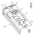
- FIG. 6 shows a decorative strip 20 'in which a fastening device 40 is arranged.
- a fastening device 40 By means of this fastening device 40, as can be seen from FIG. 7, the decorative strip 20 'on a carrier part, for example one flange-like connecting part of two body parts 10 ', 11' are fixed.
- the attachment to the carrier part is typically carried out by means of a U-shaped spring clip.
- the U-shaped spring clip is formed by a flat base part 41 of the fastening device and further by a spring leg 49 projecting from the flat base part 41.
- an additional clamping tongue 50 is also provided, which engages in a recess in the body panel 11 'and thus ensures additional securing of the clamping connection.
- the fastening device 40 is constructed from a flat base part 41 and, as can best be seen from FIGS. 6 and 8, has three adjacent functional areas, namely the holding part 42, the spring clip and a fixing area, formed by a locking part 43, the support surface 44 and the locking finger 51.
- the fastening device 40 is shown in FIG. 6 in the fastening position. In this fastening position, two opposite holding parts 45, 46 of the holding element 42, which are oriented in the opposite direction, engage in grooves 21 ', 22' of the decorative strip 20 '. These grooves 21 ', 22' are delimited by web strips 24 ', 25'.
- These web strips 24 ', 25' have a distance b 'which corresponds to the size of the receiving opening in the decorative strip for the fastening device 40.
- the fastening device 40 also has a very low overall height in this example, although in this case it is not arranged flush between the web strips 24 'and 25' of the trim strip 20 ', but, as can be seen in FIG. 7, directly on the web strips 24 ', 25' is applied.
- the bent holding parts 45 and 46 engage behind the web strips 24 'and 25' and the spring leg 49 protrudes in the opposite direction from the flat base part 41, which lies against the web strips 24 ', 25', around the carrier part 10 'and the body panel 11'. take.
- the locking element 43 is bent slightly in the direction of the trim 20 'and is supported on the web bar 25'. It would also be possible to design the locking part 43 such that it engages behind this web strip 25 '.
- the latching finger 51 is bent in the direction of the trim strip 20 'and, as can be seen in FIG. 6, engages in a notch 28 in the web strip 25'. This ensures a longitudinal fixation of the fastening device 40 in the trim 20 '.
- the fastening device 40 is also inserted into the trim 20 'by a simple rotary movement. Once the fastening device 40 is fixed in the trim 20 ', it remains in the trim 20' during normal assembly and disassembly operations of the trim 20 ', i.e. does not change its position, but can also be easily removed from the trim 20 '. For this purpose, the base part 30 is slightly lifted off the trim strip in the area of the locking element 43. The fastening device 40 is then moved in the direction of rotation 53 around the center 52 of the holding element 42 until the side edges 47, 48, 47 ', 48' of the holding parts 45, 46 are aligned parallel to the longitudinal orientation of the decorative strip.
- the fastening device 40 can be lifted out of the decorative strip 20 '.
- the holding element 42 namely has a width which is greater than the distance b 'of the web strips 24', 25 ', so that the ends of the holding parts 45, 46 engage behind the web strips 24', 25 'of the trim strip 20'.
- the release position i.e.
- the holding element 42 has a width a' which in this case corresponds to the distance between the parallel side edges 47, 48 and 47 ', 48' and this distance a 'is less than the distance b' of the sides of the web strips 24 ', 25'.
- fastening devices 30, 40 are possible for different types of decorative strips, both for anodized decorative strips and for plastic strips, since no mechanical or chemical pre-processing on the decorative strip is necessary.
Landscapes
- Engineering & Computer Science (AREA)
- General Engineering & Computer Science (AREA)
- Mechanical Engineering (AREA)
- Connection Of Plates (AREA)
- Developing Agents For Electrophotography (AREA)
- Vehicle Interior And Exterior Ornaments, Soundproofing, And Insulation (AREA)
- Supports Or Holders For Household Use (AREA)
- Slide Fasteners, Snap Fasteners, And Hook Fasteners (AREA)
- Die Bonding (AREA)
- Absorbent Articles And Supports Therefor (AREA)
- Mechanical Coupling Of Light Guides (AREA)
Applications Claiming Priority (4)
| Application Number | Priority Date | Filing Date | Title |
|---|---|---|---|
| DE20303879U DE20303879U1 (de) | 2003-03-10 | 2003-03-10 | Befestigungsvorrichtung zur lösbaren Festlegung eines Bauteils an einem Trägerteil |
| DE10310624 | 2003-03-10 | ||
| DE2003110624 DE10310624A1 (de) | 2003-03-10 | 2003-03-10 | Befestigungsvorrichtung zur lösbaren Festlegung eines Bauteils an einem Trägerteil |
| DE20303879U | 2003-03-10 |
Publications (2)
| Publication Number | Publication Date |
|---|---|
| EP1459938A1 true EP1459938A1 (fr) | 2004-09-22 |
| EP1459938B1 EP1459938B1 (fr) | 2005-05-11 |
Family
ID=32826209
Family Applications (1)
| Application Number | Title | Priority Date | Filing Date |
|---|---|---|---|
| EP04001652A Expired - Lifetime EP1459938B1 (fr) | 2003-03-10 | 2004-01-27 | Dispositif destiné à la fixation détachable d'un élément sur une partie support |
Country Status (5)
| Country | Link |
|---|---|
| EP (1) | EP1459938B1 (fr) |
| AT (1) | ATE295285T1 (fr) |
| DE (1) | DE502004000008D1 (fr) |
| ES (1) | ES2239752T3 (fr) |
| PT (1) | PT1459938E (fr) |
Cited By (2)
| Publication number | Priority date | Publication date | Assignee | Title |
|---|---|---|---|---|
| FR3039789A1 (fr) * | 2015-08-05 | 2017-02-10 | Peugeot Citroen Automobiles Sa | Fixation d'une garniture sur un cadre d'une porte de vehicule automobile |
| CN113332828A (zh) * | 2021-07-19 | 2021-09-03 | 安徽华翱新型板业有限公司 | 一种防火隔热的手工净化板 |
Families Citing this family (1)
| Publication number | Priority date | Publication date | Assignee | Title |
|---|---|---|---|---|
| DE102006023042A1 (de) * | 2006-05-17 | 2007-11-29 | Bayerische Motoren Werke Ag | Befestigungsbauteil |
Citations (3)
| Publication number | Priority date | Publication date | Assignee | Title |
|---|---|---|---|---|
| GB2024109A (en) * | 1978-05-26 | 1980-01-09 | Ravenscroft E | Improvements in or relating to two-part capping strips |
| EP0527440A1 (fr) * | 1991-08-09 | 1993-02-17 | TRW United-Carr GmbH & Co. KG | Dispositif de maintien d'une bande à un support |
| EP1146235A2 (fr) * | 2000-04-13 | 2001-10-17 | Erbslöh Aktiengesellschaft | Dispositif pour la fixation invisible d'un profil |
-
2004
- 2004-01-27 DE DE502004000008T patent/DE502004000008D1/de not_active Expired - Lifetime
- 2004-01-27 PT PT04001652T patent/PT1459938E/pt unknown
- 2004-01-27 EP EP04001652A patent/EP1459938B1/fr not_active Expired - Lifetime
- 2004-01-27 AT AT04001652T patent/ATE295285T1/de active
- 2004-01-27 ES ES04001652T patent/ES2239752T3/es not_active Expired - Lifetime
Patent Citations (3)
| Publication number | Priority date | Publication date | Assignee | Title |
|---|---|---|---|---|
| GB2024109A (en) * | 1978-05-26 | 1980-01-09 | Ravenscroft E | Improvements in or relating to two-part capping strips |
| EP0527440A1 (fr) * | 1991-08-09 | 1993-02-17 | TRW United-Carr GmbH & Co. KG | Dispositif de maintien d'une bande à un support |
| EP1146235A2 (fr) * | 2000-04-13 | 2001-10-17 | Erbslöh Aktiengesellschaft | Dispositif pour la fixation invisible d'un profil |
Cited By (2)
| Publication number | Priority date | Publication date | Assignee | Title |
|---|---|---|---|---|
| FR3039789A1 (fr) * | 2015-08-05 | 2017-02-10 | Peugeot Citroen Automobiles Sa | Fixation d'une garniture sur un cadre d'une porte de vehicule automobile |
| CN113332828A (zh) * | 2021-07-19 | 2021-09-03 | 安徽华翱新型板业有限公司 | 一种防火隔热的手工净化板 |
Also Published As
| Publication number | Publication date |
|---|---|
| ATE295285T1 (de) | 2005-05-15 |
| PT1459938E (pt) | 2005-07-29 |
| EP1459938B1 (fr) | 2005-05-11 |
| ES2239752T3 (es) | 2005-10-01 |
| DE502004000008D1 (de) | 2005-06-16 |
Similar Documents
| Publication | Publication Date | Title |
|---|---|---|
| EP2703237B1 (fr) | Module avec un capteur de pluie et une agrafe de fixation pour le capteur de pluie. | |
| DE10349449B3 (de) | Befestigungselement zur Verbindung eines Bauteils mit einem Trägerbauteil | |
| DE10159380B4 (de) | Verbindungsmutter zum Anschrauben von Konstruktionselementen an einem plattenartigen Bauteil | |
| DE10064017C2 (de) | Vorrichtung zur Verbindung eines Trägers, insbesondere eines Karosserieteils eines Kraftfahrzeuges, mit einem Plattenelement, insbesondere einer Tür- oder Wandverkleidung | |
| DE102006017878A1 (de) | Befestigungsclip | |
| DE2104050B2 (de) | Klemmhalterung | |
| DE2814656C3 (de) | Befestigung eines Verkleidungsteiles an Blechbauteilen | |
| DE202020101103U1 (de) | Rohrschelle sowie Baukasten für ihre Erstellung | |
| WO2008077858A1 (fr) | Support | |
| EP0974757A1 (fr) | Dispositif de fixation pour éléments plats | |
| EP1459938B1 (fr) | Dispositif destiné à la fixation détachable d'un élément sur une partie support | |
| EP0593909A1 (fr) | Clip d'ancrage en plastique pour enjoliveurs, protecteurs ou similaires, en particulier pour voitures | |
| DE2456009A1 (de) | Befestigung fuer einen beschlagteil, insbesondere einen eckbeschlagteil, wie eine eckumlenkung in einer c-foermigen nut eines rahmens eines fensters, einer tuer o.dgl. | |
| DE10146615B4 (de) | Laschenverbindung | |
| EP2273638A2 (fr) | Pince pour canaux de câble destinée à masquer des bords de coupe | |
| DE102005049140B4 (de) | Vorrichtung zur Befestigung eines Sensors | |
| DE602004005534T2 (de) | Elastisches Befestigungselement mit einer Verdrehsicherung | |
| EP1375275A2 (fr) | Unité d'entraínement avec un élément d' arrêt | |
| WO2002030710A1 (fr) | Dispositif pour relier un support, notamment une partie de carrosserie d'une automobile, a un element en plaque, notamment a un revetement de porte ou de paroi | |
| DE10310624A1 (de) | Befestigungsvorrichtung zur lösbaren Festlegung eines Bauteils an einem Trägerteil | |
| CH701598A1 (de) | Wechselschildhalter für Fahrzeug-Kennzeichen. | |
| DE102021107013A1 (de) | Bauteilanordnung für Kraftfahrzeuge und Verfahren zum Verbinden von Bauteilen eines Kraftfahrzeugs, sowie Instrumententafel und Fahrzeugtür | |
| DE3416677C2 (fr) | ||
| EP1371530B1 (fr) | Dispositif de fixation | |
| DE20303879U1 (de) | Befestigungsvorrichtung zur lösbaren Festlegung eines Bauteils an einem Trägerteil |
Legal Events
| Date | Code | Title | Description |
|---|---|---|---|
| PUAI | Public reference made under article 153(3) epc to a published international application that has entered the european phase |
Free format text: ORIGINAL CODE: 0009012 |
|
| 17P | Request for examination filed |
Effective date: 20040512 |
|
| AK | Designated contracting states |
Kind code of ref document: A1 Designated state(s): AT BE BG CH CY CZ DE DK EE ES FI FR GB GR HU IE IT LI LU MC NL PT RO SE SI SK TR |
|
| AX | Request for extension of the european patent |
Extension state: AL LT LV MK |
|
| GRAP | Despatch of communication of intention to grant a patent |
Free format text: ORIGINAL CODE: EPIDOSNIGR1 |
|
| GRAS | Grant fee paid |
Free format text: ORIGINAL CODE: EPIDOSNIGR3 |
|
| GRAA | (expected) grant |
Free format text: ORIGINAL CODE: 0009210 |
|
| AK | Designated contracting states |
Kind code of ref document: B1 Designated state(s): AT DE ES FI FR GB NL PT SE |
|
| REG | Reference to a national code |
Ref country code: GB Ref legal event code: FG4D Free format text: NOT ENGLISH |
|
| AKX | Designation fees paid |
Designated state(s): AT DE ES FI FR GB NL PT SE |
|
| REG | Reference to a national code |
Ref country code: IE Ref legal event code: FG4D Free format text: LANGUAGE OF EP DOCUMENT: GERMAN |
|
| REF | Corresponds to: |
Ref document number: 502004000008 Country of ref document: DE Date of ref document: 20050616 Kind code of ref document: P |
|
| REG | Reference to a national code |
Ref country code: PT Ref legal event code: SC4A Effective date: 20050603 |
|
| REG | Reference to a national code |
Ref country code: SE Ref legal event code: TRGR |
|
| REG | Reference to a national code |
Ref country code: ES Ref legal event code: FG2A Ref document number: 2239752 Country of ref document: ES Kind code of ref document: T3 |
|
| GBT | Gb: translation of ep patent filed (gb section 77(6)(a)/1977) |
Effective date: 20050914 |
|
| ET | Fr: translation filed | ||
| PLBE | No opposition filed within time limit |
Free format text: ORIGINAL CODE: 0009261 |
|
| STAA | Information on the status of an ep patent application or granted ep patent |
Free format text: STATUS: NO OPPOSITION FILED WITHIN TIME LIMIT |
|
| 26N | No opposition filed |
Effective date: 20060214 |
|
| PGFP | Annual fee paid to national office [announced via postgrant information from national office to epo] |
Ref country code: PT Payment date: 20111221 Year of fee payment: 9 |
|
| PGFP | Annual fee paid to national office [announced via postgrant information from national office to epo] |
Ref country code: FR Payment date: 20120202 Year of fee payment: 9 |
|
| PGFP | Annual fee paid to national office [announced via postgrant information from national office to epo] |
Ref country code: SE Payment date: 20120125 Year of fee payment: 9 Ref country code: FI Payment date: 20120124 Year of fee payment: 9 Ref country code: GB Payment date: 20120125 Year of fee payment: 9 |
|
| PGFP | Annual fee paid to national office [announced via postgrant information from national office to epo] |
Ref country code: NL Payment date: 20120130 Year of fee payment: 9 |
|
| PGFP | Annual fee paid to national office [announced via postgrant information from national office to epo] |
Ref country code: AT Payment date: 20120123 Year of fee payment: 9 |
|
| PGFP | Annual fee paid to national office [announced via postgrant information from national office to epo] |
Ref country code: ES Payment date: 20120111 Year of fee payment: 9 |
|
| REG | Reference to a national code |
Ref country code: PT Ref legal event code: MM4A Free format text: LAPSE DUE TO NON-PAYMENT OF FEES Effective date: 20130729 |
|
| REG | Reference to a national code |
Ref country code: NL Ref legal event code: V1 Effective date: 20130801 |
|
| REG | Reference to a national code |
Ref country code: SE Ref legal event code: EUG |
|
| REG | Reference to a national code |
Ref country code: AT Ref legal event code: MM01 Ref document number: 295285 Country of ref document: AT Kind code of ref document: T Effective date: 20130131 |
|
| GBPC | Gb: european patent ceased through non-payment of renewal fee |
Effective date: 20130127 |
|
| REG | Reference to a national code |
Ref country code: FR Ref legal event code: ST Effective date: 20130930 |
|
| PG25 | Lapsed in a contracting state [announced via postgrant information from national office to epo] |
Ref country code: AT Free format text: LAPSE BECAUSE OF NON-PAYMENT OF DUE FEES Effective date: 20130131 Ref country code: FI Free format text: LAPSE BECAUSE OF NON-PAYMENT OF DUE FEES Effective date: 20130127 Ref country code: NL Free format text: LAPSE BECAUSE OF NON-PAYMENT OF DUE FEES Effective date: 20130801 Ref country code: SE Free format text: LAPSE BECAUSE OF NON-PAYMENT OF DUE FEES Effective date: 20130128 Ref country code: PT Free format text: LAPSE BECAUSE OF NON-PAYMENT OF DUE FEES Effective date: 20130729 |
|
| PG25 | Lapsed in a contracting state [announced via postgrant information from national office to epo] |
Ref country code: FR Free format text: LAPSE BECAUSE OF NON-PAYMENT OF DUE FEES Effective date: 20130131 Ref country code: GB Free format text: LAPSE BECAUSE OF NON-PAYMENT OF DUE FEES Effective date: 20130127 |
|
| REG | Reference to a national code |
Ref country code: ES Ref legal event code: FD2A Effective date: 20140324 |
|
| PG25 | Lapsed in a contracting state [announced via postgrant information from national office to epo] |
Ref country code: ES Free format text: LAPSE BECAUSE OF NON-PAYMENT OF DUE FEES Effective date: 20130128 |
|
| REG | Reference to a national code |
Ref country code: DE Ref legal event code: R082 Ref document number: 502004000008 Country of ref document: DE Representative=s name: BUSE MENTZEL LUDEWIG PATENTANWALTSKANZLEI, DE Ref country code: DE Ref legal event code: R081 Ref document number: 502004000008 Country of ref document: DE Owner name: WKW ENGINEERING GMBH, DE Free format text: FORMER OWNER: WKW ERBSLOEH AUTOMOTIVE GMBH, 42553 VELBERT, DE |
|
| PGFP | Annual fee paid to national office [announced via postgrant information from national office to epo] |
Ref country code: DE Payment date: 20191218 Year of fee payment: 17 |
|
| REG | Reference to a national code |
Ref country code: DE Ref legal event code: R119 Ref document number: 502004000008 Country of ref document: DE |
|
| PG25 | Lapsed in a contracting state [announced via postgrant information from national office to epo] |
Ref country code: DE Free format text: LAPSE BECAUSE OF NON-PAYMENT OF DUE FEES Effective date: 20210803 |