EP2703237B1 - Module avec un capteur de pluie et une agrafe de fixation pour le capteur de pluie. - Google Patents
Module avec un capteur de pluie et une agrafe de fixation pour le capteur de pluie. Download PDFInfo
- Publication number
- EP2703237B1 EP2703237B1 EP13194255.9A EP13194255A EP2703237B1 EP 2703237 B1 EP2703237 B1 EP 2703237B1 EP 13194255 A EP13194255 A EP 13194255A EP 2703237 B1 EP2703237 B1 EP 2703237B1
- Authority
- EP
- European Patent Office
- Prior art keywords
- sensor
- assembly according
- plate
- holding
- holding clip
- Prior art date
- Legal status (The legal status is an assumption and is not a legal conclusion. Google has not performed a legal analysis and makes no representation as to the accuracy of the status listed.)
- Ceased
Links
Images






Classifications
-
- B—PERFORMING OPERATIONS; TRANSPORTING
- B60—VEHICLES IN GENERAL
- B60S—SERVICING, CLEANING, REPAIRING, SUPPORTING, LIFTING, OR MANOEUVRING OF VEHICLES, NOT OTHERWISE PROVIDED FOR
- B60S1/00—Cleaning of vehicles
- B60S1/02—Cleaning windscreens, windows or optical devices
- B60S1/04—Wipers or the like, e.g. scrapers
- B60S1/06—Wipers or the like, e.g. scrapers characterised by the drive
- B60S1/08—Wipers or the like, e.g. scrapers characterised by the drive electrically driven
- B60S1/0818—Wipers or the like, e.g. scrapers characterised by the drive electrically driven including control systems responsive to external conditions, e.g. by detection of moisture, dirt or the like
- B60S1/0822—Wipers or the like, e.g. scrapers characterised by the drive electrically driven including control systems responsive to external conditions, e.g. by detection of moisture, dirt or the like characterized by the arrangement or type of detection means
- B60S1/0874—Wipers or the like, e.g. scrapers characterised by the drive electrically driven including control systems responsive to external conditions, e.g. by detection of moisture, dirt or the like characterized by the arrangement or type of detection means characterized by the position of the sensor on the windshield
- B60S1/0881—Wipers or the like, e.g. scrapers characterised by the drive electrically driven including control systems responsive to external conditions, e.g. by detection of moisture, dirt or the like characterized by the arrangement or type of detection means characterized by the position of the sensor on the windshield characterized by the attachment means on the windshield
-
- B—PERFORMING OPERATIONS; TRANSPORTING
- B60—VEHICLES IN GENERAL
- B60S—SERVICING, CLEANING, REPAIRING, SUPPORTING, LIFTING, OR MANOEUVRING OF VEHICLES, NOT OTHERWISE PROVIDED FOR
- B60S1/00—Cleaning of vehicles
- B60S1/02—Cleaning windscreens, windows or optical devices
- B60S1/04—Wipers or the like, e.g. scrapers
- B60S1/06—Wipers or the like, e.g. scrapers characterised by the drive
- B60S1/08—Wipers or the like, e.g. scrapers characterised by the drive electrically driven
- B60S1/0818—Wipers or the like, e.g. scrapers characterised by the drive electrically driven including control systems responsive to external conditions, e.g. by detection of moisture, dirt or the like
- B60S1/0822—Wipers or the like, e.g. scrapers characterised by the drive electrically driven including control systems responsive to external conditions, e.g. by detection of moisture, dirt or the like characterized by the arrangement or type of detection means
-
- B—PERFORMING OPERATIONS; TRANSPORTING
- B60—VEHICLES IN GENERAL
- B60S—SERVICING, CLEANING, REPAIRING, SUPPORTING, LIFTING, OR MANOEUVRING OF VEHICLES, NOT OTHERWISE PROVIDED FOR
- B60S1/00—Cleaning of vehicles
- B60S1/02—Cleaning windscreens, windows or optical devices
- B60S1/04—Wipers or the like, e.g. scrapers
- B60S1/06—Wipers or the like, e.g. scrapers characterised by the drive
- B60S1/08—Wipers or the like, e.g. scrapers characterised by the drive electrically driven
- B60S1/0818—Wipers or the like, e.g. scrapers characterised by the drive electrically driven including control systems responsive to external conditions, e.g. by detection of moisture, dirt or the like
- B60S1/0822—Wipers or the like, e.g. scrapers characterised by the drive electrically driven including control systems responsive to external conditions, e.g. by detection of moisture, dirt or the like characterized by the arrangement or type of detection means
- B60S1/0874—Wipers or the like, e.g. scrapers characterised by the drive electrically driven including control systems responsive to external conditions, e.g. by detection of moisture, dirt or the like characterized by the arrangement or type of detection means characterized by the position of the sensor on the windshield
- B60S1/0888—Wipers or the like, e.g. scrapers characterised by the drive electrically driven including control systems responsive to external conditions, e.g. by detection of moisture, dirt or the like characterized by the arrangement or type of detection means characterized by the position of the sensor on the windshield characterized by the attachment of the elements in a unit
-
- G—PHYSICS
- G01—MEASURING; TESTING
- G01D—MEASURING NOT SPECIALLY ADAPTED FOR A SPECIFIC VARIABLE; ARRANGEMENTS FOR MEASURING TWO OR MORE VARIABLES NOT COVERED IN A SINGLE OTHER SUBCLASS; TARIFF METERING APPARATUS; MEASURING OR TESTING NOT OTHERWISE PROVIDED FOR
- G01D11/00—Component parts of measuring arrangements not specially adapted for a specific variable
- G01D11/24—Housings ; Casings for instruments
- G01D11/245—Housings for sensors
-
- G—PHYSICS
- G01—MEASURING; TESTING
- G01D—MEASURING NOT SPECIALLY ADAPTED FOR A SPECIFIC VARIABLE; ARRANGEMENTS FOR MEASURING TWO OR MORE VARIABLES NOT COVERED IN A SINGLE OTHER SUBCLASS; TARIFF METERING APPARATUS; MEASURING OR TESTING NOT OTHERWISE PROVIDED FOR
- G01D11/00—Component parts of measuring arrangements not specially adapted for a specific variable
- G01D11/30—Supports specially adapted for an instrument; Supports specially adapted for a set of instruments
Definitions
- the invention relates to a retaining clip with which a sensor, in particular a rain sensor, can be mounted on a holding frame.
- the invention also relates to an assembly consisting of a holding frame, which can be attached to a window of a motor vehicle, a sensor, in particular a rain sensor, and a retaining clip, by means of which the sensor can be attached to the support frame.
- a rain sensor which can be attached by means of two spring clips on a support frame.
- This type of attachment of the sensor requires a comparatively elaborately designed housing of the sensor, so that the spring clip can be attached, and requires comparatively complicated manufactured spring clip, which are provided with curved and therefore not easy to produce sections.
- the final assembly is relatively difficult because the two spring clip must be locked while the sensor must be held in the support frame.
- document EP1486388 discloses a retaining clip according to the preamble of claim 1.
- the object of the invention is to provide a retaining clip and an assembly with sensor and retaining clip, which is characterized by low manufacturing costs and reliable installation.
- a retaining clip for a sensor is provided according to the invention, with a plate which can cover the sensor, at least one support arm and at least one latching arm, which are designed so that they can engage a support frame for the sensor, wherein the retaining clip is integrally formed.
- the invention is based on the basic idea, to Attachment of the sensor to use only a single component, namely the retaining clip. This encompasses the sensor over a large area on the side facing away from the holding frame and can be latched to the holding frame with a fluid movement, in particular with a movement in a single direction.
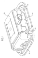
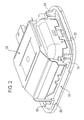
- a sensor 10 is shown that may be, in particular, a rain sensor attached to a windshield of a motor vehicle.
- the sensor 10 is inserted into a holding frame 12, which may be glued to the windshield.
- the holding frame 12 has a total of four abutments 14, which serve to lock a retaining clip 16 according to a first embodiment fixed to the holding frame 12.
- Each abutment 14 consists of a bracket 18 and a Fixiersteg 20th
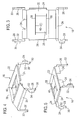
- the retaining clip 16 (see in particular the FIGS. 3 to 5 ) is a one-piece, stamped sheet metal bent part, which has a plate 22, on each side of the plate a bent edge 24, two retaining arms 26 and two latching arms 28.
- the retaining arms 26 are designed with a straight outer contour, while the latching arms 28 each have a recess 32 on its inner side.
- a wing 34 is provided in each case. The wing 34 serves on the one hand to stabilize the locking arm 28 so that despite the recess 32, the necessary strength is ensured. On the other hand, it allows to pull the corresponding locking arm behind a detent at the pre-assembly explained later.
- the plate 22 In the plate 22 are two parallel slit-like cuts 36 punched so that between them a spring tab 38 is defined.
- the spring tab 38 is bent out of the plane of the plate downwards (see in particular the FIGS. 4 and 5 ), ie on the side on which the holding arms 26 and the latching arms 28 are located. In the middle, the spring clip 38 is provided with an opening 40.
- the retaining clip 16 is preassembled on the sensor 10.
- the plate 22 is placed on the back of the sensor, so that the holding arms and the latching arms extend laterally approximately in the vicinity of the corners of the housing of the sensor 10 along the housing.
- the bent edges 24 serve to fix.
- the positioning is further enhanced by a recess on a rim 24 into which a connector 43 of the Sensor 10 is inserted.
- the housing of the sensor 10 is provided with a fixing projection 42 which engages in the opening 40 in the spring tab 38.
- two locking lugs 44 are provided, which can cooperate with the two locking arms 28.
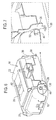
- preassembled state hold the locking lugs 44, the latching arms 28 in an elastically deflected state. More specifically, the latching arms 28 are held in a state in which their feet 30 are bent to the support arms 26, so that the distance between the feet of a latching arm 28 and a support arm 26 is reduced on one side of the housing of the sensor. It is in FIG. 7 to see that the locking lug 44 engages just below the recess 32 on the locking arm 28.
- the sensor 10 and the retaining clip 16 are inserted into the frame 12 so that the legs 30 of the retaining arms 26 engage the brackets 18 on one side of the support frame 12 (see Figs FIGS. 8 and 9 ).
- the fixing webs 20 serve for pre-fixing and prevent the holding arms 26 from slipping sideways. Since the locking lugs 44 hold the latching arms 28 in an elastically deflected state, the feet 30 of the latching arms 28 can be moved past the bracket associated with them, so that the sensor 10 with the retaining clip 16 of the in FIG. 8 shown position completely down in the in FIG. 10 shown position can be pivoted.
- FIGS. 13 to 15 The relative movement between the latching arms 28 and the locking lugs 44 on the housing of the sensor 10 is again in the FIGS. 13 to 15 shown.
- FIG. 13 the preassembled state is shown, in which the latching nose 44 keeps the latching arm 28 deflected.
- FIG. 14 the locking arm 28 is shown in the state in which it is just so far downwardly adjusted relative to the latching nose 44 that the locking lug can dip into the recess 32.
- FIG. 15 then the state is shown in which the latching arm 28 is snapped back to its initial position.
- a particular advantage of the retaining clip according to the invention and the assembly according to the invention is that the sensor can be supplied together with the pre-assembled retaining clip to the vehicle, in which already the holding frame is installed. The sensor can then be inserted together with the holding frame, which is in a precisely defined state, by means of a simple hand movement in the holding frame and pressed against this, whereby the retaining clip automatically locked. The snapping back of the locking arms also gives an acoustic feedback to the effect that the locking has been done properly.
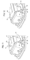
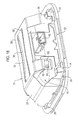
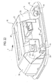
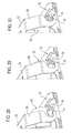
- FIGS. 16 to 30 For example, a sensor 10 with a retaining clip 16 according to a second embodiment belonging to the invention and the mounting of the sensor 10 by means of this retaining clip 16 are shown.
- the same reference numerals are used, and reference is made to the above explanations in this respect.
- a difference between the first and the second embodiment is that in the second embodiment, the two locking arms 28 do not emanate directly from the plate 22, but emanate from a connecting web 29, which in turn is connected to the plate 22.
- the two latching arms 28 and the two support arms 26 have no bent foot 30, but in each case a generally hook-shaped free end.
- a slightly widened tip 31 is provided, behind the (to the arm 26 and locking arm 28 toward) a recess is arranged. The distance to the plate 22 is less in the region of the widened tip 31 than in the region of the depression.
- the tips 31 of the support arms 26 and latching arms 28 are aligned in the same direction and not, as the feet 30 of the first embodiment, in opposite directions. Accordingly, in the second embodiment, the abutments 14 are open on the support frame 12 in the same direction, rather than in opposite directions, as in the first embodiment.
- the retaining clip 16 is provided with a mounting aid formed in the form of three lateral flaps 50. These are arranged on the longitudinal sides of the plate 22. Two tabs 50 are opposite each other, and the third is opposite to the location at which the connector 43 of the sensor 10 is arranged. Each tab has a guide slot 52 into which a guide projection 54 of the sensor 10 engages.
- the guide slot 52 is generally elongated parallel to the plate 22 and has a recess for receiving the guide pin at its front end, which has in the direction of the widened tips of the support arms 26 and latching arms 28.
- the guide slot 52 has the shape of a recumbent "L" with the short leg of the L facing downwardly away from the plate 22.
- the retaining clip 16 In the initial state ( FIG. 18 ), the retaining clip 16 is pre-mounted on the sensor 10.
- the guide projections 54 of the sensor 10 engage in the guide slots 52 of the retaining clip 16 and lie in the recesses.
- the spring tab 38 is not or only slightly biased.
- the sensor 10 is mounted on the support frame 14 by moving in the direction of the arrow P of FIG. 20 is placed on the support frame 12 so that the tips of the holder arms 26 and latching arms 28 are located in front of the abutments 14 (see the FIGS. 20, 21 . 25 and 28 ). The sensor 10 is then already in its final position.
- the retaining clip 16 in a second step in the direction of the arrow P of FIG. 22 pressed obliquely to the support frame 12, so down to the support frame 12 and to the side.
- the guide slots 52 and the guide projections 54 assist in this, since they specify the direction of movement.
Landscapes
- Engineering & Computer Science (AREA)
- Automation & Control Theory (AREA)
- Mechanical Engineering (AREA)
- Clamps And Clips (AREA)
- Measuring Temperature Or Quantity Of Heat (AREA)
Claims (14)
- Ensemble comprenant un capteur de pluie (10) et une pince de retenue (16) pour le capteur de pluie (10), la pince de retenue présentant une plaque (22) qui est apte à recouvrir le capteur, ainsi qu'au moins un bras de retenue (26) et au moins un bras d'enclenchement (28) qui sont réalisés de manière à pouvoir s'engager sur un cadre de retenue (12) pour la fixation de l'ensemble, la pince de retenue (16) étant réalisée d'un seul tenant, et le capteur de pluie (19) étant pré-monté sur la pince de retenue (16), caractérisé en ce que le capteur présente une saillie de guidage (54) qui s'engage dans une coulisse de guidage (52) d'une patte de montage (50) de la pince de retenue (16), et en ce que le capteur est pré-monté sur la pince de retenue (16) de manière imperdable au moyen de la saillie de guidage (54).
- Ensemble selon la revendication 1, caractérisé en ce que la pince de retenue (16) est une pièce de tôle pliée.
- Ensemble selon l'une des revendications précédentes, caractérisé en ce qu'au moins une patte ressort (38) est prévue dans la plaque (22), laquelle est pliée hors du plan de la plaque en direction du capteur.
- Ensemble selon la revendication 3, caractérisé en ce que la patte ressort (38) est définie par deux encoches (36) dans la plaque (22) de la pince de retenue (16).
- Ensemble selon la revendication 3 ou la revendication 4, caractérisé en ce qu'un orifice (40) pour une saillie de fixation (42) du capteur (10) est prévu dans la patte ressort (38).
- Ensemble selon l'une des revendications précédentes, caractérisé en ce que la plaque (22) est pourvue d'un bord replié (24) qui sert à fixer le capteur.
- Ensemble selon la revendication 6, caractérisé en ce que le bras de retenue (26) ou le bras d'enclenchement (28) est prévu sur le bord replié (24) de la plaque (22).
- Ensemble selon la revendication 7 ou la revendication 8, caractérisé en ce que le bord replié (24) est pourvu d'un évidement pour un connecteur enfichable (43) du capteur.
- Ensemble selon l'une des revendications 1 à 6, caractérisé en ce que la plaque (22) est pourvue d'une aide de montage (50) au moyen de laquelle la pince de retenue (16) peut être reliée au capteur (10).
- Ensemble selon la revendication 9, caractérisé en ce que l'aide de montage est réalisée à la manière d'une patte latérale (50).
- Ensemble selon la revendication 9 ou la revendication 10, caractérisé en ce que l'aide de montage présente une coulisse de guidage (52) dans laquelle une saillie de guidage (54) du capteur (10) peut s'engager.
- Ensemble selon l'une des revendications précédentes, caractérisé en ce que deux bras de retenue (26) sont prévus d'un côté de la plaque et deux bras d'enclenchement (28) sont prévus de l'autre côté.
- Ensemble selon l'une des revendications 1 à 11, caractérisé en ce que les deux bras d'enclenchement (28) sont reliés à la plaque (22) au moyen d'une barrette de raccordement (29) commune.
- Ensemble selon l'une des revendications précédentes, caractérisé en ce que l'ensemble présente un cadre de retenue (12) qui est apte à être monté sur une vitre d'un véhicule automobile.
Applications Claiming Priority (3)
| Application Number | Priority Date | Filing Date | Title |
|---|---|---|---|
| DE200620000853 DE202006000853U1 (de) | 2006-01-19 | 2006-01-19 | Halteklammer für einen Regensensor |
| DE102006040213.8A DE102006040213C5 (de) | 2006-01-19 | 2006-08-28 | Halteklammer für einen Regensensor |
| EP07000497.3A EP1810896B1 (fr) | 2006-01-19 | 2007-01-11 | Module avec un capteur de pluie et une agrafe de fixation pour le capteur de pluie. |
Related Parent Applications (2)
| Application Number | Title | Priority Date | Filing Date |
|---|---|---|---|
| EP07000497.3A Division-Into EP1810896B1 (fr) | 2006-01-19 | 2007-01-11 | Module avec un capteur de pluie et une agrafe de fixation pour le capteur de pluie. |
| EP07000497.3A Division EP1810896B1 (fr) | 2006-01-19 | 2007-01-11 | Module avec un capteur de pluie et une agrafe de fixation pour le capteur de pluie. |
Publications (2)
| Publication Number | Publication Date |
|---|---|
| EP2703237A1 EP2703237A1 (fr) | 2014-03-05 |
| EP2703237B1 true EP2703237B1 (fr) | 2014-10-22 |
Family
ID=38016667
Family Applications (2)
| Application Number | Title | Priority Date | Filing Date |
|---|---|---|---|
| EP13194255.9A Ceased EP2703237B1 (fr) | 2006-01-19 | 2007-01-11 | Module avec un capteur de pluie et une agrafe de fixation pour le capteur de pluie. |
| EP07000497.3A Ceased EP1810896B1 (fr) | 2006-01-19 | 2007-01-11 | Module avec un capteur de pluie et une agrafe de fixation pour le capteur de pluie. |
Family Applications After (1)
| Application Number | Title | Priority Date | Filing Date |
|---|---|---|---|
| EP07000497.3A Ceased EP1810896B1 (fr) | 2006-01-19 | 2007-01-11 | Module avec un capteur de pluie et une agrafe de fixation pour le capteur de pluie. |
Country Status (6)
| Country | Link |
|---|---|
| US (1) | US8763970B2 (fr) |
| EP (2) | EP2703237B1 (fr) |
| JP (1) | JP4527737B2 (fr) |
| BR (1) | BRPI0700101A (fr) |
| DE (1) | DE102006040213C5 (fr) |
| MX (1) | MX2007000731A (fr) |
Families Citing this family (29)
| Publication number | Priority date | Publication date | Assignee | Title |
|---|---|---|---|---|
| JP2007537910A (ja) * | 2004-03-26 | 2007-12-27 | プレー・ゲゼルシャフト・ミト・ベシュレンクテル・ハフツング | センサー用支持部材の保持フレーム |
| DE102006061308A1 (de) * | 2006-12-22 | 2008-06-26 | Leopold Kostal Gmbh & Co. Kg | Halterung |
| DE102007057139A1 (de) * | 2007-11-28 | 2009-06-04 | Robert Bosch Gmbh | Sensor, insbesondere Regensensor und/oder Lichtsensor |
| DE202008003168U1 (de) * | 2008-03-06 | 2008-06-26 | Trw Automotive Electronics & Components Gmbh | Sensor mit Halterung |
| DE102008028978B4 (de) * | 2008-06-18 | 2019-11-14 | Leopold Kostal Gmbh & Co. Kg | Sensoranordnung für ein Kraftfahrzeug |
| US8436260B2 (en) * | 2008-07-29 | 2013-05-07 | Cts Corporation | Coil retention assembly for electronic assembly |
| DE102008044840A1 (de) * | 2008-08-28 | 2010-03-04 | Leopold Kostal Gmbh & Co. Kg | Sensoranordnung für ein Kraftfahrzeug |
| DE102010010571A1 (de) * | 2010-03-05 | 2011-09-08 | Conti Temic Microelectronic Gmbh | Befestigungsvorrichtung für Sensorgehäuse in einem Kraftfahrzeuginnenraum |
| US10046716B2 (en) | 2011-02-10 | 2018-08-14 | Denso Corporation | In-vehicle camera and vehicle control system |
| US9380219B2 (en) | 2011-04-20 | 2016-06-28 | Magna Electronics Inc. | Angular filter for vehicle mounted cameras |
| DE102011108594A1 (de) * | 2011-07-26 | 2013-01-31 | Daimler Ag | Befestigungsanordnung eines Sensorelements an einem Befestigungselement eines Kraftwagens |
| US9871971B2 (en) | 2011-08-02 | 2018-01-16 | Magma Electronics Inc. | Vehicle vision system with light baffling system |
| US9596387B2 (en) | 2011-08-02 | 2017-03-14 | Magna Electronics Inc. | Vehicular camera system |
| DE102011121003A1 (de) * | 2011-12-13 | 2013-06-13 | Daimler Ag | Trägervorrichtung zur Befestigung an einer Scheibe sowie Befestigungsanordnung einer Kamera oder dergleichen an einer solchen Trägervorrichtung |
| DE102012101781B4 (de) * | 2012-03-02 | 2014-07-10 | Continental Automotive Gmbh | Halterahmen für Sensorvorrichtungen in Fahrzeugen |
| US9244249B2 (en) * | 2012-09-28 | 2016-01-26 | Gentex Corporation | Double ball slide on mount with screw over sensor |
| JP2015152489A (ja) * | 2014-02-17 | 2015-08-24 | 株式会社デンソー | ガラス面装着センサ装置 |
| US9260071B2 (en) * | 2014-03-11 | 2016-02-16 | Trw Automotive U.S. Llc | Apparatus for snap mounting a crash sensor |
| JP6052246B2 (ja) * | 2014-07-10 | 2016-12-27 | トヨタ自動車株式会社 | 車載カメラの取り付け構造 |
| JP6392267B2 (ja) * | 2016-03-24 | 2018-09-19 | 本田技研工業株式会社 | センサブラケット |
| JP6307545B2 (ja) * | 2016-03-24 | 2018-04-04 | 本田技研工業株式会社 | センサブラケット |
| EP3279043B1 (fr) * | 2016-08-05 | 2018-12-05 | MEAS France | Système d'assemblage de capteurs |
| US10953817B2 (en) * | 2017-08-15 | 2021-03-23 | Methode Electronics, Inc. | Locking bracket for vehicle accessory |
| DE102017120242A1 (de) * | 2017-09-04 | 2019-03-07 | Peiker Acustic Gmbh & Co. Kg | Telematikeinheit, Baugruppe eines Fahrzeugs und Verfahren zur Montage und Demontage einer Telematikeinheit |
| DE102018206548A1 (de) | 2018-04-27 | 2019-10-31 | Robert Bosch Gmbh | Verfahren zur Detektion von Beschädigungen und/oder Verunreinigungen auf einem transparenten Abdeckmaterial eines optoelektronischen Sensors, System, optoelektronischer Sensor und Fortbewegungsmittel |
| JP7225633B2 (ja) * | 2018-09-25 | 2023-02-21 | 富士フイルムビジネスイノベーション株式会社 | センサーホルダーおよびセンサー・ハウジングユニット |
| JP7390243B2 (ja) * | 2020-04-17 | 2023-12-01 | 株式会社ニフコ | 車載機器用ブラケット |
| US11345290B2 (en) * | 2020-09-30 | 2022-05-31 | Zf Friedrichshafen Ag | Mounting arrangement |
| DE102021118716B4 (de) | 2021-07-20 | 2025-03-20 | Valeo Schalter Und Sensoren Gmbh | Kameravorrichtung für ein fahrzeug und fahrzeug |
Family Cites Families (33)
| Publication number | Priority date | Publication date | Assignee | Title |
|---|---|---|---|---|
| DE4202121C1 (en) * | 1992-01-27 | 1992-12-24 | Leopold Kostal Gmbh & Co Kg, 5880 Luedenscheid, De | Sensor assembly detecting wetness of motor vehicle windscreen - includes receiver for radiation reflected from precipitation esp. drops of rain |
| JPH06324628A (ja) * | 1993-04-26 | 1994-11-25 | At & T Global Inf Solutions Internatl Inc | 価格表示器取付装置 |
| DE4410217C2 (de) * | 1994-03-24 | 2003-12-11 | Bosch Gmbh Robert | Befestigung und Ankopplung eines opto-elektronischen Sensors an einer Scheibe sowie Aufbau des Sensors |
| JPH09688A (ja) | 1995-06-16 | 1997-01-07 | Tetsuya Ando | 検出装置 |
| JPH09180566A (ja) | 1995-12-26 | 1997-07-11 | Omron Corp | スイッチユニット |
| JPH10142070A (ja) | 1996-11-06 | 1998-05-29 | Denso Corp | ヒータユニットの水温センサ取付構造 |
| DE19804165A1 (de) * | 1997-08-19 | 1999-02-25 | Itt Mfg Enterprises Inc | Mit einem Silicon-Gel an eine Scheibe angekoppelter Sensor |
| EP1027204B1 (fr) * | 1997-08-19 | 2003-09-24 | Valeo Wischersysteme GmbH | Capteur couple a une vitre par un gel de silicone |
| JP3975563B2 (ja) | 1998-07-13 | 2007-09-12 | 株式会社デンソー | 雨滴センサ |
| DE29906013U1 (de) * | 1999-04-01 | 1999-06-17 | Reitter & Schefenacker GmbH & Co. KG, 73730 Esslingen | Innenrückblickspiegel für Fahrzeuge, insbesondere für Kraftfahrzeuge |
| JP4098440B2 (ja) * | 1999-05-21 | 2008-06-11 | ナイルス株式会社 | 降雨状態検出方法及び降雨状態検出装置 |
| DE29924838U1 (de) * | 1999-07-17 | 2006-01-12 | Robert Bosch Gmbh | Sensor zum optischen Erfassen von Fremdkörpern, insbesondere Regentropfen, auf einer Scheibe |
| US6367752B1 (en) * | 1999-10-20 | 2002-04-09 | Ncr Corporation | Electronic price label mounting apparatus |
| US6698701B1 (en) * | 2000-11-15 | 2004-03-02 | Ncr Corporation | Electronic shelf label mounting apparatus |
| DE10129038A1 (de) * | 2001-06-15 | 2002-12-19 | Bosch Gmbh Robert | Regensensor, insbesondere für ein Kraftfahrzeug, sowie Verfahren zur Montage eines Regensensors |
| FR2827420B1 (fr) * | 2001-07-10 | 2006-08-11 | Ifm Electronic Gmbh | Dispositif de fixation pour des detecteurs tels que des capteurs de proximite |
| DE10156241A1 (de) * | 2001-11-15 | 2003-06-05 | Hella Kg Hueck & Co | Sensoreinrichtung |
| TW515764B (en) * | 2002-01-09 | 2003-01-01 | Lite On Automotive Corp | Wheel rim having sensor |
| FR2839016A1 (fr) * | 2002-04-30 | 2003-10-31 | Johnson Contr Automotive Elect | Embase de fixation d'un boitier capteur de pression de pneumatique pour vehicule automobile, boitier associe et procede de montage |
| EP1576924B1 (fr) * | 2002-09-30 | 2007-08-22 | KerrHawe SA | Support de détecteur digitale médico-dentaire |
| DE10256835B4 (de) * | 2002-12-04 | 2011-03-17 | SMR Patents S.à.r.l. | Innenspiegelanordnung für ein Kraftfahrzeug |
| DE10261246A1 (de) | 2002-12-20 | 2004-07-01 | Robert Bosch Gmbh | Regensensor, insbesondere für ein Kraftfahrzeug |
| DE10309758A1 (de) | 2003-03-06 | 2004-09-16 | Leopold Kostal Gmbh & Co Kg | Sensoreinrichtung |
| DE10314018A1 (de) * | 2003-03-28 | 2004-10-07 | Daimlerchrysler Ag | Halterung an einer Windschutzscheibe |
| EP1628843B1 (fr) * | 2003-06-02 | 2009-04-15 | Continental Automotive France | Unite roue pour dispositif de surveillance de la pression des pneus d'un vehicule automobile |
| DE10326853A1 (de) * | 2003-06-14 | 2004-12-30 | Hella Kgaa Hueck & Co. | Sensoreinrichtung zur Erfassung der Benetzung einer Scheibe |
| DE10326854A1 (de) | 2003-06-14 | 2004-12-30 | Hella Kgaa Hueck & Co. | Sensoreinrichtung zur Erfassung der Benetzung einer Scheibe |
| DE10326855A1 (de) * | 2003-06-14 | 2004-12-30 | Hella Kgaa Hueck & Co. | Optoelektronische Sensoreinrichtung |
| DE10328468B4 (de) * | 2003-06-25 | 2017-06-08 | Kronowetter Kunststoff- Und Metalltechnik Gmbh | Spiegelklebeplatte zur Befestigung eines Innenspiegels an einer Fensterscheibe eines Kraftfahrzeugs |
| JP4207808B2 (ja) * | 2004-03-03 | 2009-01-14 | 株式会社東京精密 | 揺動支点部材 |
| JP2006012644A (ja) | 2004-06-25 | 2006-01-12 | Matsushita Electric Works Ltd | 熱線センサ付き自動スイッチ |
| DE102004032749B3 (de) | 2004-07-07 | 2006-01-05 | A. Raymond & Cie | Vorrichtung zum Befestigen eines Regensensors an einem Träger |
| DE202006000853U1 (de) * | 2006-01-19 | 2007-05-24 | Trw Automotive Electronics & Components Gmbh & Co. Kg | Halteklammer für einen Regensensor |
-
2006
- 2006-08-28 DE DE102006040213.8A patent/DE102006040213C5/de not_active Expired - Fee Related
-
2007
- 2007-01-11 EP EP13194255.9A patent/EP2703237B1/fr not_active Ceased
- 2007-01-11 EP EP07000497.3A patent/EP1810896B1/fr not_active Ceased
- 2007-01-18 US US11/654,708 patent/US8763970B2/en not_active Expired - Fee Related
- 2007-01-18 BR BRPI0700101-0A patent/BRPI0700101A/pt not_active IP Right Cessation
- 2007-01-18 MX MX2007000731A patent/MX2007000731A/es active IP Right Grant
- 2007-01-19 JP JP2007010042A patent/JP4527737B2/ja not_active Expired - Fee Related
Also Published As
| Publication number | Publication date |
|---|---|
| EP1810896A2 (fr) | 2007-07-25 |
| EP1810896B1 (fr) | 2014-11-12 |
| US20070164188A1 (en) | 2007-07-19 |
| DE102006040213B4 (de) | 2014-02-13 |
| DE102006040213A1 (de) | 2007-08-02 |
| MX2007000731A (es) | 2009-02-11 |
| EP2703237A1 (fr) | 2014-03-05 |
| EP1810896A3 (fr) | 2010-01-27 |
| BRPI0700101A (pt) | 2007-11-06 |
| US8763970B2 (en) | 2014-07-01 |
| JP4527737B2 (ja) | 2010-08-18 |
| DE102006040213C5 (de) | 2019-08-01 |
| JP2007225601A (ja) | 2007-09-06 |
Similar Documents
| Publication | Publication Date | Title |
|---|---|---|
| EP2703237B1 (fr) | Module avec un capteur de pluie et une agrafe de fixation pour le capteur de pluie. | |
| EP1732792B1 (fr) | Raclette d'essuie-glace | |
| EP3685057B1 (fr) | Connecteur pourvu d'élément de fixation pour pièce rapportée | |
| EP2614203B1 (fr) | Deviateur pour cable pour lève-vitre à câble | |
| WO2002034593A1 (fr) | Dispositif de connexion d'un bras d'essuie-glace a un balai d'essuie-glace et bras d'essuie-glace et balai d'essuie-glace faisant intervenir un tel dispositif | |
| EP2193277A1 (fr) | Dispositif de fixation d'une pièce rapportée sur un élément support | |
| EP2477853B1 (fr) | Balai d'essuie-glace à structure en forme de barre plate | |
| EP2838766B1 (fr) | Dispositif balai d'essuie-glace | |
| WO2011101080A1 (fr) | Arrangement de fixation pour fixer un composant sur une paroi porteuse et élément de fixation à cet effet | |
| WO2001042063A1 (fr) | Dispositif de fixation dote d'une tole elastique d'arret et destine a une ferrure d'ancrage d'une ceinture de securite | |
| DE202006000853U1 (de) | Halteklammer für einen Regensensor | |
| DE102013112846B4 (de) | Anordnung zum Befestigen eines ersten Karosserieteils an einem zweiten Karosserieteil eines Kraftfahrzeugs | |
| EP2642896B1 (fr) | Rail de contenant pour caisson de tiroir | |
| WO2008077858A1 (fr) | Support | |
| DE3625063C2 (fr) | ||
| EP0709267B1 (fr) | Dispositif d'essuie-glaces de véhicules automobiles | |
| EP0609534B1 (fr) | Dispositif pour fixer des pièces, en particulier des pièces de véhicules à moteur | |
| EP2097298B1 (fr) | Balai d'essuie-glace | |
| DE102015211045B4 (de) | Frontendmodul für ein Kraftfahrzeug sowie Anordnung eines solchen Frontendmoduls an einem Montageträger eines Kraftfahrzeugs | |
| DE102004057400B4 (de) | Anordnung bestehend aus einem Verkleidungsteil und einem Bauteil | |
| WO2001030624A1 (fr) | Ressort de maintien pour l'assemblage articule d'une raclette d'essuie-glace avec un bras d'essuie-glace d'un vehicule automobile et dispositif d'essuie-glace correspondant | |
| EP2017104B1 (fr) | Dispositif de fixation pour une vitre mobile d'un véhicule automobile | |
| WO2012072241A1 (fr) | Dispositif de fixation pour un module de sac gonflable | |
| DE102010062906A1 (de) | Wischblattvorrichtung | |
| DE102005049140A1 (de) | Vorrichtung zur Befestigung eines Sensors |
Legal Events
| Date | Code | Title | Description |
|---|---|---|---|
| AC | Divisional application: reference to earlier application |
Ref document number: 1810896 Country of ref document: EP Kind code of ref document: P |
|
| AK | Designated contracting states |
Kind code of ref document: A1 Designated state(s): DE FR IT |
|
| PUAI | Public reference made under article 153(3) epc to a published international application that has entered the european phase |
Free format text: ORIGINAL CODE: 0009012 |
|
| 17P | Request for examination filed |
Effective date: 20140219 |
|
| RBV | Designated contracting states (corrected) |
Designated state(s): DE FR IT |
|
| GRAP | Despatch of communication of intention to grant a patent |
Free format text: ORIGINAL CODE: EPIDOSNIGR1 |
|
| INTG | Intention to grant announced |
Effective date: 20140519 |
|
| GRAS | Grant fee paid |
Free format text: ORIGINAL CODE: EPIDOSNIGR3 |
|
| GRAA | (expected) grant |
Free format text: ORIGINAL CODE: 0009210 |
|
| AC | Divisional application: reference to earlier application |
Ref document number: 1810896 Country of ref document: EP Kind code of ref document: P |
|
| AK | Designated contracting states |
Kind code of ref document: B1 Designated state(s): DE FR IT |
|
| REG | Reference to a national code |
Ref country code: DE Ref legal event code: R096 Ref document number: 502007013531 Country of ref document: DE Effective date: 20141211 |
|
| REG | Reference to a national code |
Ref country code: FR Ref legal event code: PLFP Year of fee payment: 9 |
|
| REG | Reference to a national code |
Ref country code: DE Ref legal event code: R097 Ref document number: 502007013531 Country of ref document: DE |
|
| PLBE | No opposition filed within time limit |
Free format text: ORIGINAL CODE: 0009261 |
|
| STAA | Information on the status of an ep patent application or granted ep patent |
Free format text: STATUS: NO OPPOSITION FILED WITHIN TIME LIMIT |
|
| 26N | No opposition filed |
Effective date: 20150723 |
|
| REG | Reference to a national code |
Ref country code: FR Ref legal event code: PLFP Year of fee payment: 10 |
|
| REG | Reference to a national code |
Ref country code: FR Ref legal event code: PLFP Year of fee payment: 11 |
|
| REG | Reference to a national code |
Ref country code: FR Ref legal event code: PLFP Year of fee payment: 12 |
|
| PGFP | Annual fee paid to national office [announced via postgrant information from national office to epo] |
Ref country code: DE Payment date: 20180129 Year of fee payment: 12 |
|
| PGFP | Annual fee paid to national office [announced via postgrant information from national office to epo] |
Ref country code: IT Payment date: 20190124 Year of fee payment: 13 Ref country code: FR Payment date: 20190124 Year of fee payment: 13 |
|
| REG | Reference to a national code |
Ref country code: DE Ref legal event code: R119 Ref document number: 502007013531 Country of ref document: DE |
|
| PG25 | Lapsed in a contracting state [announced via postgrant information from national office to epo] |
Ref country code: DE Free format text: LAPSE BECAUSE OF NON-PAYMENT OF DUE FEES Effective date: 20190801 |
|
| PG25 | Lapsed in a contracting state [announced via postgrant information from national office to epo] |
Ref country code: FR Free format text: LAPSE BECAUSE OF NON-PAYMENT OF DUE FEES Effective date: 20200131 |
|
| PG25 | Lapsed in a contracting state [announced via postgrant information from national office to epo] |
Ref country code: IT Free format text: LAPSE BECAUSE OF NON-PAYMENT OF DUE FEES Effective date: 20200111 |