EP1459971A2 - Amortisseur de direction pour vehicule - Google Patents
Amortisseur de direction pour vehicule Download PDFInfo
- Publication number
- EP1459971A2 EP1459971A2 EP04006414A EP04006414A EP1459971A2 EP 1459971 A2 EP1459971 A2 EP 1459971A2 EP 04006414 A EP04006414 A EP 04006414A EP 04006414 A EP04006414 A EP 04006414A EP 1459971 A2 EP1459971 A2 EP 1459971A2
- Authority
- EP
- European Patent Office
- Prior art keywords
- damper
- housing
- steering
- attached
- control valve
- Prior art date
- Legal status (The legal status is an assumption and is not a legal conclusion. Google has not performed a legal analysis and makes no representation as to the accuracy of the status listed.)
- Granted
Links
Images


Classifications
-
- F—MECHANICAL ENGINEERING; LIGHTING; HEATING; WEAPONS; BLASTING
- F16—ENGINEERING ELEMENTS AND UNITS; GENERAL MEASURES FOR PRODUCING AND MAINTAINING EFFECTIVE FUNCTIONING OF MACHINES OR INSTALLATIONS; THERMAL INSULATION IN GENERAL
- F16F—SPRINGS; SHOCK-ABSORBERS; MEANS FOR DAMPING VIBRATION
- F16F9/00—Springs, vibration-dampers, shock-absorbers, or similarly-constructed movement-dampers using a fluid or the equivalent as damping medium
- F16F9/10—Springs, vibration-dampers, shock-absorbers, or similarly-constructed movement-dampers using a fluid or the equivalent as damping medium using liquid only; using a fluid of which the nature is immaterial
- F16F9/14—Devices with one or more members, e.g. pistons, vanes, moving to and fro in chambers and using throttling effect
- F16F9/145—Devices with one or more members, e.g. pistons, vanes, moving to and fro in chambers and using throttling effect involving only rotary movement of the effective parts
-
- B—PERFORMING OPERATIONS; TRANSPORTING
- B62—LAND VEHICLES FOR TRAVELLING OTHERWISE THAN ON RAILS
- B62K—CYCLES; CYCLE FRAMES; CYCLE STEERING DEVICES; RIDER-OPERATED TERMINAL CONTROLS SPECIALLY ADAPTED FOR CYCLES; CYCLE AXLE SUSPENSIONS; CYCLE SIDECARS, FORECARS, OR THE LIKE
- B62K21/00—Steering devices
- B62K21/08—Steering dampers
Definitions
- the steering damper according to the first aspect also includes a shaft (for example, a damper shaft 53 in the embodiment) having a base portion of the vane connected thereto in a fixed state, and supporting the vane for rocking motion with respect to the housing, and a hydraulic pressure control valve (for example, a hydraulic pressure control valve 68 in the embodiment) for varying the attenuating force of the steering damper.
- a shaft for example, a damper shaft 53 in the embodiment
- a hydraulic pressure control valve for example, a hydraulic pressure control valve 68 in the embodiment
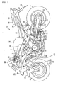
- Figure 1 is a side elevational view of a motorcycle, incorporating a selected illustrative embodiment of the present invention.
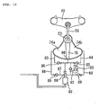
- Figure 12 is a sectional view of the steering damper, taken along line E-E of FIG 10.
- the vehicle body frame 2 also includes a main frame 7, which extends obliquely rearwardly and downwardly from the head pipe 3.
- the main frame 7 is bifurcated and forks to the left and right as it extends behind the head pipe 3.
- the main frame 7 further extends rearwardly through a bent portion thereof, as shown.
- a pivot connection 8 is provided at a front end portion of a substantially central portion of the portion of the main frame 7 which extends downwardly, and a rear fork 10 is supported by the pivot connection 8 for rocking motion.
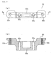
- the second bracket 55 has a base portion 55a formed in a substantially parallelepiped block shape, and left and right wing portions 55b, 55b extending upwardly from the opposite sides of the base portion.
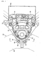
- a recess 14a is formed at a front portion of the fuel tank 14, in order to prevent interference of the fuel tank 14 with the steering damper 51 and/or the first and second brackets 54 and 55. It is to be noted that, in FIG 2, reference numeral 70 denotes an ignition switch disposed forwardly of the head pipe 3.
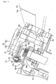
- a bushing 78 is fitted at a portion of the damper shaft 53 on the upper side thereof, with respect to the location of the damper shaft 53 at which the sealing washer 77a is fitted. Further, a circlip 79 is fitted at another portion of the damper shaft 53, below the bushing 78 and above the vane 75. Meanwhile, a bushing 80 and an oil seal 81 are fitted at a portion of the damper shaft 53 below the lower side sealing washer 77b.
- the check valves 85 permit the working fluid to flow from the oil chambers 74a and 74b to the oil path 86 side through the oil paths 83 and 84, but block the working fluid to flow in the reverse direction.
- the check valves 89 permit the working fluid to flow to the oil chambers 74a and 74b side through the oil path 88, but block the working fluid to flow in the reverse direction.
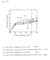
- linear solenoid 69 is controlled by a control section (not shown), so that higher exciting force is exhibited as the vehicle speed or the acceleration of the vehicle body increases.
- the linear solenoid 69 is controlled in accordance with the vehicle speed or the acceleration of the vehicle body and is controlled by a control section (not shown) so that, for example, the exciting force increases as the vehicle speed increases or as the acceleration of the vehicle body increases. Accordingly, at this time, the opening timing of the hydraulic pressure control valve 68 is delayed, and besides, even after the hydraulic pressure control valve 68 is opened, the valvc opening is smaller by an amount corresponding to the increase of the exciting force and increased attenuating force is exhibited. In short, as the vehicle speed increases or as the acceleration increases, increased attenuating force is exhibited.
- damper shaft 53 when the damper shaft 53 is attached to the steering system 50, it is attached through the linkage 56. Therefore, when the damper housing 52 is to be attached to the top bridge 49, even if the damper shaft 53 is attached in a displaced relationship from the axial line of the head pipe 3 or the steering stem 6, the function of the steering damper 51 is not deteriorated.
- the linear solenoid 69 is used as the actuator for the hydraulic pressure control valve 68
- the actuator is not limited to this, but another alternative actuator may be used instead, which utilizes a hydraulic pressure or the like.
Landscapes
- Engineering & Computer Science (AREA)
- Mechanical Engineering (AREA)
- General Engineering & Computer Science (AREA)
- Fluid-Damping Devices (AREA)
Applications Claiming Priority (4)
| Application Number | Priority Date | Filing Date | Title |
|---|---|---|---|
| JP2003079156 | 2003-03-20 | ||
| JP2003079158A JP4198497B2 (ja) | 2003-03-20 | 2003-03-20 | 自動二輪車におけるステアリングダンパの取付構造 |
| JP2003079158 | 2003-03-20 | ||
| JP2003079156A JP4342820B2 (ja) | 2003-03-20 | 2003-03-20 | 車両用ステアリングダンパ |
Publications (3)
| Publication Number | Publication Date |
|---|---|
| EP1459971A2 true EP1459971A2 (fr) | 2004-09-22 |
| EP1459971A3 EP1459971A3 (fr) | 2004-11-17 |
| EP1459971B1 EP1459971B1 (fr) | 2006-05-24 |
Family
ID=32829024
Family Applications (1)
| Application Number | Title | Priority Date | Filing Date |
|---|---|---|---|
| EP04006414A Expired - Lifetime EP1459971B1 (fr) | 2003-03-20 | 2004-03-17 | Amortisseur de direction pour vehicule |
Country Status (3)
| Country | Link |
|---|---|
| US (1) | US7021433B2 (fr) |
| EP (1) | EP1459971B1 (fr) |
| DE (1) | DE602004000932T2 (fr) |
Cited By (7)
| Publication number | Priority date | Publication date | Assignee | Title |
|---|---|---|---|---|
| EP1481882A2 (fr) | 2003-05-28 | 2004-12-01 | HONDA MOTOR CO., Ltd. | Amortisseur de direction |
| EP1514786A1 (fr) * | 2003-09-09 | 2005-03-16 | HONDA MOTOR CO., Ltd. | Amortisseur de direction pour véhicule, et véhicule l'incorporant |
| EP1707483A1 (fr) * | 2005-03-31 | 2006-10-04 | Honda Motor Co., Ltd. | Structure de montage d'un amortisseur de direction |
| EP1759975A3 (fr) * | 2005-08-30 | 2008-05-07 | Showa Corporation | Amortisseur de direction |
| EP2130754A1 (fr) * | 2008-06-04 | 2009-12-09 | Yamaha Hatsudoki Kabushiki Kaisha | Système d'amortisseur de direction, et véhicule de type à monture doté de celui-ci |
| EP2261529A3 (fr) * | 2005-02-17 | 2011-01-19 | Ralph S. Norman | Stabilisateur amortissant à fluide |
| DE102006002725B4 (de) * | 2005-02-16 | 2014-05-22 | Honda Motor Co., Ltd. | Rotations-Dämpfer |
Families Citing this family (17)
| Publication number | Priority date | Publication date | Assignee | Title |
|---|---|---|---|---|
| US7789207B2 (en) * | 2002-06-10 | 2010-09-07 | Norman Ralph S | Stabilizer |
| JP4271468B2 (ja) * | 2003-03-20 | 2009-06-03 | 本田技研工業株式会社 | ロータリーダンパ |
| JP4493074B2 (ja) * | 2004-02-05 | 2010-06-30 | 本田技研工業株式会社 | 自動2輪車のステアリングダンパ装置 |
| JP4555750B2 (ja) * | 2004-09-28 | 2010-10-06 | 本田技研工業株式会社 | ステアリングダンパ装置 |
| EP1851421B8 (fr) * | 2005-02-24 | 2020-06-17 | Fitzgerald, Kevin A. | Moteur a combustion interne, a pistons libres alternatifs, quatre cylindres, quatre temps,, a course variable, a allumage par compression de charge premelangee |
| US7631735B1 (en) * | 2006-05-03 | 2009-12-15 | Vanvalkenburgh Charlie N | Mounting system for rotary damper |
| JP4909763B2 (ja) * | 2007-02-23 | 2012-04-04 | カヤバ工業株式会社 | ステアリングダンパ |
| WO2008108731A1 (fr) * | 2007-03-05 | 2008-09-12 | öHLINS RACING AB | Amortisseur de direction et dispositif pour monter un amortisseur de direction |
| SE532539C2 (sv) * | 2007-06-14 | 2010-02-16 | Oehlins Racing Ab | Vingdämpare med justerbar dämpkraft |
| US7970511B2 (en) * | 2008-02-06 | 2011-06-28 | Honda Motor Company, Ltd. | Electronic steering damper systems and vehicles including same |
| DE102008011858B4 (de) | 2008-02-29 | 2009-12-24 | Gebrüder Frei GmbH & Co. KG | Vorrichtung zur Dämpfung einer Drehbewegung |
| DE102008002629A1 (de) * | 2008-06-25 | 2009-12-31 | Zf Friedrichshafen Ag | Drehschwingungsdämpfer für ein Kraftfahrzeugfahrwerk |
| AR079383A1 (es) | 2010-12-27 | 2012-01-25 | Fischer Hugo Alfredo | Dispositivo estabilizador de direccion para vehiculos con columna y manillar. |
| WO2012149980A1 (fr) * | 2011-05-05 | 2012-11-08 | öHLINS RACING AB | Amortisseur de direction comportant un réglage actif des caractéristiques d'amortissement |
| US9863450B1 (en) * | 2014-04-16 | 2018-01-09 | Rockwell Collins, Inc. | Hydro-mechanical device with preloaded flow regulating assembly |
| US10301792B2 (en) * | 2015-04-30 | 2019-05-28 | Micromatic Llc | Hydraulic dampener for use on mine shovels |
| CN112896401B (zh) * | 2021-03-17 | 2022-07-26 | 浙江春风动力股份有限公司 | 一种摩托车转向系统 |
Family Cites Families (10)
| Publication number | Priority date | Publication date | Assignee | Title |
|---|---|---|---|---|
| US2814362A (en) * | 1954-12-06 | 1957-11-26 | Jr Morgan L Sweeney | Vibration damping apparatus |
| US3419114A (en) * | 1967-09-18 | 1968-12-31 | Houdaille Industries Inc | Hydraulic action devices with inertia insensitive snubbing circuit |
| JP4640905B2 (ja) | 2001-04-06 | 2011-03-02 | 本田技研工業株式会社 | ステアリングダンパ装置 |
| JP4493068B2 (ja) | 2001-09-07 | 2010-06-30 | 本田技研工業株式会社 | 鞍乗り型車両用ステアリングダンパ装置 |
| JP4197592B2 (ja) * | 2001-12-28 | 2008-12-17 | 本田技研工業株式会社 | ステアリングダンパ装置 |
| JP4197591B2 (ja) * | 2001-12-28 | 2008-12-17 | 本田技研工業株式会社 | ステアリングダンパ装置 |
| US6824153B2 (en) | 2002-06-21 | 2004-11-30 | Kayaba Industry Co., Ltd. | Steering device |
| US6802519B2 (en) * | 2002-09-09 | 2004-10-12 | Rtt Motorsports, Llc | Steering damper |
| JP4271468B2 (ja) * | 2003-03-20 | 2009-06-03 | 本田技研工業株式会社 | ロータリーダンパ |
| JP4545392B2 (ja) * | 2003-05-28 | 2010-09-15 | 本田技研工業株式会社 | ステアリングダンパ |
-
2004
- 2004-03-09 US US10/796,572 patent/US7021433B2/en not_active Expired - Fee Related
- 2004-03-17 DE DE602004000932T patent/DE602004000932T2/de not_active Expired - Lifetime
- 2004-03-17 EP EP04006414A patent/EP1459971B1/fr not_active Expired - Lifetime
Cited By (15)
| Publication number | Priority date | Publication date | Assignee | Title |
|---|---|---|---|---|
| EP1481882A2 (fr) | 2003-05-28 | 2004-12-01 | HONDA MOTOR CO., Ltd. | Amortisseur de direction |
| EP1481882A3 (fr) * | 2003-05-28 | 2007-07-18 | HONDA MOTOR CO., Ltd. | Amortisseur de direction |
| US7267350B2 (en) | 2003-05-28 | 2007-09-11 | Honda Motor Co., Ltd | Steering damper |
| EP1514786A1 (fr) * | 2003-09-09 | 2005-03-16 | HONDA MOTOR CO., Ltd. | Amortisseur de direction pour véhicule, et véhicule l'incorporant |
| US7258356B2 (en) | 2003-09-09 | 2007-08-21 | Honda Motor Co., Ltd. | Vehicle steering damper apparatus, and vehicle incorporating same |
| DE102006002725B4 (de) * | 2005-02-16 | 2014-05-22 | Honda Motor Co., Ltd. | Rotations-Dämpfer |
| EP2261527A3 (fr) * | 2005-02-17 | 2011-01-19 | Ralph S. Norman | Stabilisateur amortissant à fluide |
| EP2261528A3 (fr) * | 2005-02-17 | 2011-01-19 | Ralph S. Norman | Stabilisateur amortissant à fluide |
| EP2261529A3 (fr) * | 2005-02-17 | 2011-01-19 | Ralph S. Norman | Stabilisateur amortissant à fluide |
| US7712756B2 (en) | 2005-03-31 | 2010-05-11 | Honda Motor Co., Ltd. | Steering damper mounting structure |
| CN100465056C (zh) * | 2005-03-31 | 2009-03-04 | 本田技研工业株式会社 | 转向减震器安装结构 |
| EP1707483A1 (fr) * | 2005-03-31 | 2006-10-04 | Honda Motor Co., Ltd. | Structure de montage d'un amortisseur de direction |
| EP1759975A3 (fr) * | 2005-08-30 | 2008-05-07 | Showa Corporation | Amortisseur de direction |
| EP2130754A1 (fr) * | 2008-06-04 | 2009-12-09 | Yamaha Hatsudoki Kabushiki Kaisha | Système d'amortisseur de direction, et véhicule de type à monture doté de celui-ci |
| US8775024B2 (en) | 2008-06-04 | 2014-07-08 | Yamaha Hatsudoki Kabushiki Kaisha | Steering damper system, and a saddle riding type vehicle having the same |
Also Published As
| Publication number | Publication date |
|---|---|
| US7021433B2 (en) | 2006-04-04 |
| DE602004000932T2 (de) | 2006-11-02 |
| EP1459971A3 (fr) | 2004-11-17 |
| DE602004000932D1 (de) | 2006-06-29 |
| EP1459971B1 (fr) | 2006-05-24 |
| US20040200680A1 (en) | 2004-10-14 |
Similar Documents
| Publication | Publication Date | Title |
|---|---|---|
| EP1459971B1 (fr) | Amortisseur de direction pour vehicule | |
| EP1481882B1 (fr) | Amortisseur de direction | |
| US7258211B2 (en) | Rotary damper | |
| JP4909763B2 (ja) | ステアリングダンパ | |
| US7712756B2 (en) | Steering damper mounting structure | |
| US5005859A (en) | Motor vehicle suspension with rotary damper | |
| EP1514787B1 (fr) | Suspension à bras oscillant | |
| EP1580110B1 (fr) | Amortisseur de direction | |
| JP4726041B2 (ja) | ロータリダンパ | |
| JP2006022946A (ja) | ロータリダンパ | |
| JP4342820B2 (ja) | 車両用ステアリングダンパ | |
| JP4342981B2 (ja) | ロータリーダンパ | |
| JP4463489B2 (ja) | 自動二輪車におけるステアリングダンパの取付構造 | |
| JP4198497B2 (ja) | 自動二輪車におけるステアリングダンパの取付構造 | |
| JPH0996330A (ja) | ロータリダンパ | |
| JP3727089B2 (ja) | 倒立型フロントフォーク | |
| JP4428806B2 (ja) | 車両の操舵装置 | |
| JP4153390B2 (ja) | 車両用ステアリングダンパ手段 | |
| JP3035872B2 (ja) | 油圧緩衝器 | |
| JPH11139329A (ja) | パワーステアリングの油圧コントロールバルブ装置 | |
| JPH1182597A (ja) | 車両用緩衝装置 | |
| JP6494682B2 (ja) | 鞍乗り型車両用ステアリングダンパ装置 | |
| JP3765017B2 (ja) | 油圧緩衝器 | |
| JP2000120751A (ja) | ロータリダンパ | |
| JP2006144863A (ja) | ロータリダンパ |
Legal Events
| Date | Code | Title | Description |
|---|---|---|---|
| PUAI | Public reference made under article 153(3) epc to a published international application that has entered the european phase |
Free format text: ORIGINAL CODE: 0009012 |
|
| AK | Designated contracting states |
Kind code of ref document: A2 Designated state(s): AT BE BG CH CY CZ DE DK EE ES FI FR GB GR HU IE IT LI LU MC NL PL PT RO SE SI SK TR |
|
| AX | Request for extension of the european patent |
Extension state: AL LT LV MK |
|
| PUAL | Search report despatched |
Free format text: ORIGINAL CODE: 0009013 |
|
| 17P | Request for examination filed |
Effective date: 20040810 |
|
| RIC1 | Information provided on ipc code assigned before grant |
Ipc: 7F 16F 9/14 B Ipc: 7B 62K 21/08 A |
|
| AK | Designated contracting states |
Kind code of ref document: A3 Designated state(s): AT BE BG CH CY CZ DE DK EE ES FI FR GB GR HU IE IT LI LU MC NL PL PT RO SE SI SK TR |
|
| AX | Request for extension of the european patent |
Extension state: AL LT LV MK |
|
| 17Q | First examination report despatched |
Effective date: 20050203 |
|
| AKX | Designation fees paid |
Designated state(s): DE GB IT |
|
| GRAP | Despatch of communication of intention to grant a patent |
Free format text: ORIGINAL CODE: EPIDOSNIGR1 |
|
| GRAS | Grant fee paid |
Free format text: ORIGINAL CODE: EPIDOSNIGR3 |
|
| GRAA | (expected) grant |
Free format text: ORIGINAL CODE: 0009210 |
|
| AK | Designated contracting states |
Kind code of ref document: B1 Designated state(s): DE GB IT |
|
| PG25 | Lapsed in a contracting state [announced via postgrant information from national office to epo] |
Ref country code: IT Free format text: LAPSE BECAUSE OF FAILURE TO SUBMIT A TRANSLATION OF THE DESCRIPTION OR TO PAY THE FEE WITHIN THE PRESCRIBED TIME-LIMIT;WARNING: LAPSES OF ITALIAN PATENTS WITH EFFECTIVE DATE BEFORE 2007 MAY HAVE OCCURRED AT ANY TIME BEFORE 2007. THE CORRECT EFFECTIVE DATE MAY BE DIFFERENT FROM THE ONE RECORDED. Effective date: 20060524 |
|
| REG | Reference to a national code |
Ref country code: GB Ref legal event code: FG4D |
|
| REF | Corresponds to: |
Ref document number: 602004000932 Country of ref document: DE Date of ref document: 20060629 Kind code of ref document: P |
|
| PLBE | No opposition filed within time limit |
Free format text: ORIGINAL CODE: 0009261 |
|
| STAA | Information on the status of an ep patent application or granted ep patent |
Free format text: STATUS: NO OPPOSITION FILED WITHIN TIME LIMIT |
|
| 26N | No opposition filed |
Effective date: 20070227 |
|
| REG | Reference to a national code |
Ref country code: GB Ref legal event code: 746 Effective date: 20121113 |
|
| REG | Reference to a national code |
Ref country code: DE Ref legal event code: R084 Ref document number: 602004000932 Country of ref document: DE Effective date: 20121113 |
|
| PGFP | Annual fee paid to national office [announced via postgrant information from national office to epo] |
Ref country code: GB Payment date: 20170315 Year of fee payment: 14 |
|
| PGFP | Annual fee paid to national office [announced via postgrant information from national office to epo] |
Ref country code: IT Payment date: 20170320 Year of fee payment: 14 |
|
| GBPC | Gb: european patent ceased through non-payment of renewal fee |
Effective date: 20180317 |
|
| PG25 | Lapsed in a contracting state [announced via postgrant information from national office to epo] |
Ref country code: IT Free format text: LAPSE BECAUSE OF NON-PAYMENT OF DUE FEES Effective date: 20180317 Ref country code: GB Free format text: LAPSE BECAUSE OF NON-PAYMENT OF DUE FEES Effective date: 20180317 |
|
| PGFP | Annual fee paid to national office [announced via postgrant information from national office to epo] |
Ref country code: DE Payment date: 20190305 Year of fee payment: 16 |
|
| REG | Reference to a national code |
Ref country code: DE Ref legal event code: R119 Ref document number: 602004000932 Country of ref document: DE |
|
| PG25 | Lapsed in a contracting state [announced via postgrant information from national office to epo] |
Ref country code: DE Free format text: LAPSE BECAUSE OF NON-PAYMENT OF DUE FEES Effective date: 20201001 |